Sign In
Upload
Manuals
Brands
Planmeca Manuals
Medical Equipment
ProMax 3D Max
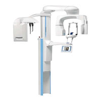
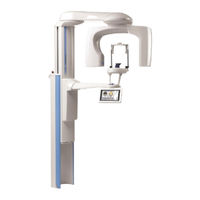
Planmeca ProMax 3D Max Manuals
Manuals and User Guides for Planmeca ProMax 3D Max. We have
3
Planmeca ProMax 3D Max manuals available for free PDF download: Technical Manual, User Manual
Planmeca ProMax 3D Max Technical Manual (234 pages)
Brand:
Planmeca
| Category:
Medical Equipment
| Size: 52 MB
Table of Contents
Table of Contents
3
General and Technical Data
7
Introduction
7
Manual Versions
7
Associated Documentation
7
Training
7
Warnings and Cautions
8
Symbols on Product Labels
9
Technical Data for Planmeca Promax Product Family
10
User's Statement
14
Radiation Leakage Technique Factors
14
Filtration
14
Maximum Attenuation Equivalent of the Front Panel of the 3D Sensor Head
15
Rated Line Voltage
15
Maximum Line Current
15
Technique Factors that Constitute the Maximum Line Current Condition
15
Generator Rating and Duty Cycle
15
Maximum Deviation of Peak Tube Potential from Indicated Value
15
Maximum Deviation of Tube Current from Indicated Value
15
Maximum Deviation of Exposure Time from Indicated Value
15
Definition of Measurement Criteria
15
CTDI Values (96 Kv Tube)
25
CTDI Values (120 Kv Tube)
28
Air Kerma
31
Stray Radiation Measurements
32
Handling Precautions for Pcbs and Software Chips
34
Handling Printed Circuit Boards
34
Handling Software Flash Memory Chips
35
EMC Information
35
User Interface
40
Switches and Buttons
40
On/Off Switch
40
Emergency Button
40
Patient Positioning Controls
41
Adjusting Exposure Sound Volume Level
42
Touch Screen
45
Overview
45
Calibrating Touch Screen Display
46
Information Displays
47
Entering Additional Settings Menus
47
Network Settings (1400)
48
Main Network Settings
49
Sensor Network Settings
49
Proceph Network Settings
50
Network Settings Reset
51
Resetting X-Ray Unit IP Address
51
Resetting 3D Sensor IP Address
52
Clinic Management Settings
56
Technical Settings
57
Entering Technical Settings Menu
57
Configuring Unit Settings
57
Performing Filament Definition
62
Entering Calibrations Menu
63
Setting Parameter Limits
63
Checking Exposure Statistics
65
Clearing Error History
66
Setting Maintenance Reminder
66
Changing X-Ray Unit Mode
67
Diagnostics and Troubleshooting
69
Showing Component Information
69
Log Management
71
Testing Ethernet Mode
72
Testing Communication between X-Ray Unit Components
73
Running Diagnostics
76
Input Connections
79
Input Connections (INP2)
80
Input Connections (Ed2/Ed3)
80
Help and Error Messages
81
Help Messages
81
Error Messages
83
Motorised Motion Related Errors (E2Xx)
84
X-Ray Generation Related Errors (E3Xx)
88
Feedback Errors (E4Xx)
89
Communication Errors (E6Xx)
92
Calibration Errors (E7Xx)
93
System Conflicts (E8Xx)
94
Infrastructure Errors (E9Xx)
95
Preventive Maintenance
97
System Maintenance
97
Cleaning
97
Operating Checks
97
Preventive Maintenance Checks
98
General
98
X-Ray Unit Adjustments and Quality Control Checks
99
X-Ray Tube Feedback System
100
Electrical Safety Measurements
102
Mechanical Checks
104
Column Motor Nut
104
Cephalostat Ear Posts Fluent Motion
105
Panoramic and 3D Calibrations
106
Required Calibration Tools
107
Adjusting Panoramic Beam and Patient Positioning Mechanism
109
Recommended Adjustment Procedures
110
Adjusting Smartpan Beam Position
110
Adjusting Collimator Angle
112
Calibrating Angle Sensors
121
Calibrating Patient Support Table Movements
127
Calibrations
130
Smartpan Beam Check and Sensor Flat Field Calibration
132
Patient Positioning Table and Positioning Lights Adjustment
132
Taking Ball Phantom Exposure
137
Panoramic Mode Patient Positioning Lights
148
Traditional Adjustment Procedures
157
Adjusting Smartpan Beam Position
158
Adjusting Collimator Angle
158
Adjusting Patient Positioning Mechanism
158
Calibrating Patient Support Table Movements
170
Calibrating Angle Sensors
170
Smartpan Beam Check and Sensor Flat Field Calibration
170
Taking Ball Phantom Exposure
170
Panoramic Mode Patient Positioning Lights
171
Adjusting 3D Lights Position
171
Calibrations
178
Patient Support Arm
181
Removing Covers
181
Removing Patient Support Table Cover
181
Detaching User Interface and Support Arm Lower Cover
182
Replacing Patient Position Control PCB
182
Adjusting Arm Tilt
184
Adjusting Lift Screw
184
Column Adjustments
186
Adjusting Telescopic Column Position
186
Calibrating Column Motor Position Sensor
188
Setting Column Maximum Height
190
Setting Column Motor Maximum Speed
191
Calibrating Patient Support Sensor
192
Adjusting Patient Support Optical Sensor
194
Adjusting Patient Support Safety Switch
196
Parts Replacement and Repair
197
Removing and Replacing Covers
197
Removing Sensor Covers
197
Removing C-Arm Upper Covers
199
Removing C-Arm Inner Cover
200
Removing Tube Head Covers (96 Kv Tube)
200
Removing Tube Head Covers (120 Kv Tube)
202
Removing Shoulder Arm Covers
205
Removing Patient Support Arm Covers
206
Removing Column Covers
206
Removing and Replacing Pcbs
212
Replacing Column Pcbs
212
Removing Patient Position Control PCB
219
Replacing / Upgrading Software
219
Replacing Power Cable
219
Replacing Other Components
221
Replacing Column Battery on RTC PCB
221
Appendix A: Diagrams
222
Input PCB
222
Ed3 New Input2 Wiring Diagram
223
Ed2 Input Module Wiring Diagram
224
CPU1 PCB Wiring Diagram
225
C-Arms Pcbs
226
C-Arm PCB Wiring Diagram
226
C-Arm PCB (120 Kv Tube Head) Wiring Diagram
227
PPC PCB Wiring Diagram
228
PSU PCB Wiring Diagram
229
Ethernet PCB Wiring Diagram
230
Cephalostat Pcbs
231
Planmeca Promax Ceph PCB Wiring Diagram
231
Planmeca Proceph PCB Wiring Diagram
232
Advertisement
Planmeca ProMax 3D Max Technical Manual (192 pages)
Brand:
Planmeca
| Category:
Medical Equipment
| Size: 11 MB
Table of Contents
Table of Contents
3
Chapter a GENERAL & TECHNICAL DATA
7
Warnings and Cautions
7
Manual Versions
8
Symbols on Product Labels
9
Technical Specifications
10
User's Statement
11
Ctdi Values
17
Stray Radiation Measurements
20
HANDLING PRECAUTIONS for Pcbs and SOFTWARE CHIPS
22
Handling Printed Circuit Boards
22
Handling Software Flash Memory Chips
22
Emc Information
23
Chapter B INFORMATION DISPLAYS
27
General about Information Displays
27
Contents of the Information Displays
28
USER PREFERENCE SETTINGS (I200
29
FEATURE PROGRAM CONTROL (I300
34
SPECIAL FUNCTIONS (I400
35
SERVICE SETTINGS (I500
42
Special Operation Mode Selection
43
Config Settings
44
Preheat Calibration
44
Lift Motor Calibrations
45
Exposure Program Tuning
46
Factory Default Settings
46
Configuration Selftest
47
Select Configuration
47
Patient Support Alignment
48
GUI Software Update
49
TECHNICAL CALIBRATIONS (I600
50
Demo "Dancing Promax
51
TROUBLESHOOTING (I700
53
Dimax Communication
54
Network Status
55
Sensor Communication
55
Chapter C HELP & ERROR MESSAGES
57
Main Categories
57
Help Messages
58
Error Messages
60
Motorized Motion Related Errors (E2Xx
60
X-Ray Generation Related Errors (E3Xx
62
Feedback Errors (E4Xx
63
Calibration Errors (E7Xx
63
System Conflicts (E8Xx
64
Infrastructure Errors (E9Xx
64
Chapter D PREVENTIVE MAINTENANCE
65
System Maintenance
65
Cleaning
65
Operator's Checks
65
Preventive Maintenance Checks
66
General
66
X-Ray Tube Feedback System
66
Mechanical Checks
69
Column Motor Nut
69
Chapter E C-ARM and SHOULDER ARM
71
Adjusting and Calibrating X-Ray Beam
71
Radiation Protection
71
Procedure from Step 1 to Step 9
72
Tools Required
73
Step 1: Checking/Adjusting Collimator Angle
76
Step 2: Alignment in X-Direction
77
Step 3: Alignment in Y-Direction
83
Step 4: Adjusting Laser Lights
85
Checking/Adjusting Position of Tomographic Lights
85
Volume Bottom Light
91
Checking/Adjusting Position of Midsagittal Plane Light
92
Checking/Adjusting Position of Incisor Light
95
Checking/Adjusting Position of Column Light
98
Step 5: Taking a Beam Check Exposure
100
Step 6: Calibrating the Patient Positioning Mechanism Height
105
Step 7: Flat Field Calibration
107
Step 8: Geometry Calibration
111
STEP 1: C-Arm and Elbow Arm Cogs: Check/Calibration
111
STEP 2: Geometry Calibrations
122
Step 9: Quality Assurance (Q/A) Test
133
Other Adjustments and Calibrations
138
Calibrating Angle Sensors
138
Removing Covers
143
Sensor Covers
143
C-Arm Upper Covers
145
C-Arm Inner Cover
146
Tube Head Covers
147
Shoulder Arm Covers
149
Updating Reconstruction Pc Software
151
Chapter F PATIENT SUPPORT ARM
153
Removing the Covers
153
Patient Support Table Cover
153
Support Arm Lower Cover
154
Gui Software Update
156
Replacing Pcbs
157
Patient Position Control PCB
157
Graphic User Interface (GUI) PCB
158
Chapter G COLUMN
161
Adjustments
161
Adjusting the Telescopic Column Position
161
Calibrating the Column Motor Position Sensor
163
Patient Support Sensor Calibration
167
Patient Support Optical Sensor Adjustment
169
Patient Support Safety Switch Adjustment
171
Removing the Covers
172
Removing the Telescopic Column Upper Front Panel
172
Removing the Telescopic Column Rear Cover Plates
174
Upgrading Software
175
Replacing the Battery on the Rtc Pcb
177
Replacing Pcbs
178
Power PCB
178
ETHERNET PCB and CPU PCB
183
Input PCB
184
Chapter H DIAGRAMS
188
Planmeca ProMax 3D Max User Manual (66 pages)
Brand:
Planmeca
| Category:
Medical Equipment
| Size: 4 MB
Table of Contents
Table of Contents
3
Introduction
5
Symbols on Product Labels
6
Associated Documentation
6
Warnings and Precautions
7
Main Parts
9
General View of System
9
General View of X-Ray Unit
10
Exposure Switch
11
Patient Supports
12
Emergency Stop Button
12
Switching X-Ray Unit on
13
Programs
14
3D Dental
14
ENT (Ear, Nose and Throat)
19
Control Panel
24
Selecting Program Type
25
Selecting Patient Size
26
Selecting Kilovolt and Milliampere Values
26
Selecting Target Area
27
Selecting Target Coordinates (Volumes with Ø100 MM or Less)
29
Selecting Image Resolution
30
Selecting Patient Entry Position
30
Information Displays
31
User Preference Settings (I200)
32
Feature Program Control (I300)
37
Special Functions (I400)
38
Patient Positioning Controls
42
3D Exposure
44
Step 1: before Exposure
44
Steps 2-5: Selecting Exposure Settings
46
Step 6: Patient Positioning
47
Step 7: Adjusting Position of Target Area
48
Step 8: Taking an Exposure
52
Taking Preview Images
54
Cleaning
56
Service
56
Disposal
57
Help Messages
58
Error Messages
60
Connecting Cables
61
Connecting Exposure Switch Cable
61
Connecting External Control Panel Cable (Optional)
62
Disconnecting Cables
62
Technical Specifications
63
Technical Data
63
Dimensions in MM (In.)
64
Minimum Operational Space Requirements
64
Advertisement
Advertisement
Related Products
Planmeca ProMax 3D Plus
Planmeca ProMax 3D Mid
Planmeca Planmeca ProMax 3D s
Planmeca Planmeca ProMax 3D Classic
Planmeca PlanMill 30 S
Planmeca ProMax
Planmeca ProMax Pan/Ceph
Planmeca ProMax 2D S3
Planmeca ProMax X-ray
Planmeca 12370003
Planmeca Categories
Medical Equipment
Dental equipment
Pet Care Product
Indoor Furnishing
Recording Equipment
More Planmeca Manuals
Login
Sign In
OR
Sign in with Facebook
Sign in with Google
Upload manual
Upload from disk
Upload from URL