Table of Contents
Advertisement
Quick Links
Advertisement
Table of Contents

Related Manuals for Planmeca ProMax 3D Max


Summary of Contents for Planmeca ProMax 3D Max
- Page 1 Planmeca ProMax 3D Max user's manual...
-
Page 3: Table Of Contents
11.4 Step 7: Adjusting position of target area ..............44 11.5 Step 8: Taking an exposure ..................48 11.6 Taking preview images ....................50 CLEANING .....................52 SERVICE ......................52 DISPOSAL .....................53 HELP MESSAGES ..................54 ERROR MESSAGES ..................56 Planmeca ProMax 3D Max 1 User’s Manual... - Page 4 IEC 60364 - equipment is used according to the operating instructions Planmeca pursues a policy of continual product development. Although every effort is made to produce up-to-date product documentation this publication should not be regarded as an infallible guide to current specifications. We reserve the right to make changes without prior notice.
-
Page 5: Introduction
INTRODUCTION INTRODUCTION The Planmeca ProMax 3D Max X-ray unit uses cone beam volumetric tomography produce three- dimensional X-ray images. The images can be used for examination of dentomaxillofacial, ear, nose and throat, as well as other cranial anatomies. The X-ray unit is allowed to be used only under supervision of a dental / health care professional. -
Page 6: Symbols On Product Labels
Electrostatic sensitive device (Standard IEC 60417) Separate collection for electrical and electronic equipment according to Directive 2002 / 96 / EC (WEEE). ASSOCIATED DOCUMENTATION The Planmeca ProMax 3D Max X-ray unit is supplied with the following manuals: - User’s Manual - Installation Manual... -
Page 7: Warnings And Precautions
+20°C and +25°C at all times. NOTE If the X-ray system is not connected to an Uninterruptible Power Supply (UPS), disconnect the system from mains during lightning storms. User’s Manual Planmeca ProMax 3D Max 3... - Page 8 X-ray unit. Keep loose items of clothing, hair and jewellery tucked away safely. NOTE Do not touch the arm structures when the X-ray unit is moving. 4 Planmeca ProMax 3D Max User’s Manual...
-
Page 9: Main Parts
MAIN PARTS MAIN PARTS General view of system X-ray unit Image Acquisition Work Station - Romexis Imaging Software - Romexis Image Database 3D Reconstruction Server Ethernet Printer User’s Manual Planmeca ProMax 3D Max 5... -
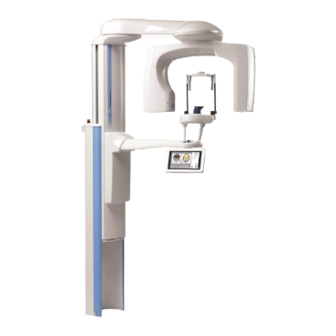
Page 10: General View Of X-Ray Unit
MAIN PARTS General view of X-ray unit C-arm Emergency stop 3D sensor button Patient support Patient support table Patient handles Patient positioning Stationary column controls Control panel Telescopic column Chair (included in delivery) 6 Planmeca ProMax 3D Max User’s Manual... -
Page 11: Exposure Switch
C-arm will stop moving and a help message will appear on the control panel display. Guide the patient away from the X-ray unit. Then clear the help message by touching OK. User’s Manual Planmeca ProMax 3D Max 7... -
Page 12: Patient Supports
A help message will appear on the control panel display. Guide the patient away from the X-ray unit. Then release the emergency stop button. The X-ray unit will automatically restart. Emergency stop button 8 Planmeca ProMax 3D Max User’s Manual... -
Page 13: Switching X-Ray Unit On
The X-ray unit is then ready for use. On / off switch NOTE To prolong the lifetime of the Planmeca ProMax 3D Max X-ray unit, always switch the X-ray unit off when it is not in active use. User’s Manual... -
Page 14: Programs
PROGRAMS PROGRAMS The Planmeca ProMax 3D Max X-ray unit uses cone beam volumetric tomography (CBVT) to produce three- dimensional X-ray images. The images can be used for examination of dentomaxillofacial, ear, nose and throat, as well as other cranial anatomies. - Page 15 The preprogrammed target areas for program type Tooth are (average jaw size): Tooth Ø50 mm Example: Example: Adult, Tooth, Ø50 mm, Adult, Tooth, Ø50 mm, Mandible H55 mm, Incisor Maxilla H55 mm, Incisor User’s Manual Planmeca ProMax 3D Max 11...
- Page 16 H90 mm, Teeth The preprogrammed target areas for program type Jaw are (average jaw size): Jaw Ø130 mm Example: Example: Adult, Jaw, Ø130 mm, Adult, Jaw, Ø130 mm, Mandible H55 mm, Teeth H90 mm, Teeth 12 Planmeca ProMax 3D Max User’s Manual...
- Page 17 The preprogrammed target areas for program type Face are (average jaw size): Face Ø100 mm Example: Adult, Face, Ø100 mm, H130 mm Example: Adult, Face, Ø130 mm, H130 mm Face Ø130 mm Example: Adult, Face, Ø130 mm, H160 mm User’s Manual Planmeca ProMax 3D Max 13...
- Page 18 The imaging procedure is carried out in two stages. The lower volume is imaged first (1/2) and the upper volume second (2/2). The C-arm is automatically moved upwards between the volumes. 14 Planmeca ProMax 3D Max User’s Manual...
-
Page 19: Ent (Ear, Nose And Throat)
TEMPORAL BONE PAIR 2 x Ø85 x H75 mm VERTEBRAE Ø85 x H75 mm Ø85 x H110 mm AIRWAYS Ø85 x H75 mm Ø110 x H110 mm Ø85 x H110 mm Ø110 x H136 mm User’s Manual Planmeca ProMax 3D Max 15... - Page 20 Ø130 x H160 mm The preprogrammed target areas for program type Sinus are (average jaw size): Sinus Ø100 mm Example: Adult, Sinus, Ø100 mm, H130 mm Sinus Ø130 mm Example: Adult, Sinus, Ø130 mm, H130 mm 16 Planmeca ProMax 3D Max User’s Manual...
- Page 21 Program type Middle Ear Pair takes two symmetrical images: one from the left (1/2) and one from the right (2/2) side of the patient. The imaging procedure is carried out in two stages. User’s Manual Planmeca ProMax 3D Max 17...
- Page 22 Program type Temporal Bone Pair takes two symmetrical images: one from the left (1/2) and one from the right (2/2) side of the patient. The imaging procedure is carried out in two stages. 18 Planmeca ProMax 3D Max User’s Manual...
- Page 23 Adult, Vertebrae, Ø100 mm, H90 mm The preprogrammed target areas for program type Airways are (average jaw size): Airways Ø100 mm Example: Adult, Airways, Ø100 mm, H90 mm Example: Airways Ø130 mm Adult, Airways, Ø130 mm, H130 mm User’s Manual Planmeca ProMax 3D Max 19...
-
Page 24: Control Panel
NOTE The exposure time indicated on the display before an exposure is taken is an estimated value. The real value is shown after the exposure. Variation in exposure time is caused by mA automation. 20 Planmeca ProMax 3D Max User’s Manual... -
Page 25: Selecting Program Type
CONTROL PANEL Selecting program type The Planmeca ProMax 3D Max X-ray unit offers two program packages: 3D Dental and 3D ENT (Ear, Nose and Throat). The program package 3D Dental is included as standard and the program package 3D ENT is available as an option. -
Page 26: Selecting Patient Size
The preset exposure values for each patient size are shown in the quick buttons at the bottom of the display. Quick buttons NOTE Selecting kV and mA values manually will override the automatic quick button setting. 22 Planmeca ProMax 3D Max User’s Manual... -
Page 27: Selecting Target Area
Selecting any of the three patient sizes in the middle will automatically change the jaw size setting to Average. Selecting the largest patient size will automatically change the jaw size setting to Wide. User’s Manual Planmeca ProMax 3D Max 23... - Page 28 - 136 / 160 mm (child / adult). In program type Skull the volume height can be set to: - Lower (child & adult 160 mm) - Upper (child & adult 160 mm) - 260 mm (child & adult). 24 Planmeca ProMax 3D Max User’s Manual...
-
Page 29: Selecting Target Coordinates (Volumes With Ø100 Mm Or Less)
NOTE The position of the target area can also be adjusted by using the positioning joystick. NOTE The y coordinate can also be adjusted by moving the thumb wheel that is located on the underside of the patient support table. User’s Manual Planmeca ProMax 3D Max 25... -
Page 30: Selecting Image Resolution
NOTE If needed, the Go Entry 1 function can be disabled as described in section “Behavioural preferences (i230)” on page 30. This might be necessary if there is no space for the C-arm to move back. 26 Planmeca ProMax 3D Max User’s Manual... -
Page 31: Information Displays
To get to the list of the Information displays, first touch the i field. The display shown below appears. You can return to the main display by touching the Exit field. User’s Manual Planmeca ProMax 3D Max 27... -
Page 32: User Preference Settings (I200)
(i210). If you want to change the date, select Set date. The option Date & time display format allows you to select the format you wish to use for displaying date and time. 28 Planmeca ProMax 3D Max User’s Manual... - Page 33 Select the time and date format you wish to use. The selected options will be marked with a blue dot. Confirm your selections by touching Done or exit the display without saving changes by touching the Cancel field. User’s Manual Planmeca ProMax 3D Max 29...
- Page 34 Note, however, that the automatic function works only if the exposure button is pressed and held down for the entire duration of the exposure. 30 Planmeca ProMax 3D Max User’s Manual...
- Page 35 Select Touch panel calibration to calibrate the touch panel. Touch panel calibration adjusts the panel to respond to the pressure level of your finger touch. A black calibration display will appear. Touch the User’s Manual Planmeca ProMax 3D Max 31...
- Page 36 Select the language of your choice. The selected language will be marked with a blue dot. Confirm your selection by touching Done. Touching the Cancel field will bring you back to the User preference settings (i200) display. 32 Planmeca ProMax 3D Max User’s Manual...
-
Page 37: Feature Program Control (I300)
On the Enable / disable features display, touch the feature you wish to activate. Enabled features will be marked with a green check mark. Confirm the selection by touching Done. User’s Manual Planmeca ProMax 3D Max 33... -
Page 38: Special Functions (I400)
To disable the selected feature repeat the procedure. NOTE After enabling / disabling a new feature the X-ray unit must be restarted. Special functions (i400) Touch Special functions (i400) on Information Displays. A list of special functions appears. 34 Planmeca ProMax 3D Max User’s Manual... - Page 39 “Waiting for Ready” status the communication to the PC cannot be disabled. Close the Romexis program before disabling the communication. NOTE Radiation or PC communication cannot be activated if demo licenses are switched on (i510). User’s Manual Planmeca ProMax 3D Max 35...
- Page 40 (i400) display. The display shown below appears. The Exposure statistics display contains various statistical data about the X-ray unit, e.g. date and time of the last exposure, total number of exposures and total exposure time. 36 Planmeca ProMax 3D Max User’s Manual...
- Page 41 If the error message reappears, contact your service technician for help. Network settings (i480) Refer to the Technical Manual for further information on network settings. User’s Manual Planmeca ProMax 3D Max 37...
-
Page 42: Patient Positioning Controls
X-ray unit down before you position the patient in the unit. Positioning joystick The positioning joystick is used for horizontal fine- adjustment of the target area. It is used when the patient is positioned in the X-ray unit. 38 Planmeca ProMax 3D Max User’s Manual... - Page 43 Press the temple support button to open the temple supports. The temple supports can be closed by pressing the temple support button again. NOTE The temple supports can be disabled as described in section “Behavioural preferences (i230)” on page 30. User’s Manual Planmeca ProMax 3D Max 39...
-
Page 44: 3D Exposure
(Part number 10028108) Support bars Support bars Insert the support bars into the holes in the patient support table and secure them in position by tightening Locking knobs the locking knobs. Patient support table 40 Planmeca ProMax 3D Max User’s Manual... - Page 45 X-ray unit. NOTE High contrast objects, such as gold teeth or amalgam, may cause artefacts in the image. Adapter Place a protective lead apron over the patient’s back if required. User’s Manual Planmeca ProMax 3D Max 41...
-
Page 46: Steps 2-5: Selecting Exposure Settings
NOTE Always try to minimize the radiation dose to the patient. Exposure values for image resolution Normal, High and HD PATIENT SIZE kV VALUE mA VALUE Child Adolescent Small adult Average-sized adult Large adult 42 Planmeca ProMax 3D Max User’s Manual... -
Page 47: Step 6: Patient Positioning
Touch the Go 3D field on the main display to move the C-arm to the selected target position. The following positioning lights will come on: Volume bottom light Volume center lights Incisor light User’s Manual Planmeca ProMax 3D Max 43... -
Page 48: Step 7: Adjusting Position Of Target Area
/ down button. The lower edge of the volume will move accordingly. Volume bottom light Move target area down 44 Planmeca ProMax 3D Max User’s Manual... - Page 49 This incisor light position indicates the front edge of the image volume when a front target area is selected. Thumb wheel Volume center lights Incisor light = Volume front edge for front targets User’s Manual Planmeca ProMax 3D Max 45...
- Page 50 Target field on the main display. A display will appear where you can adjust the x / y coordinates by touching the left / right arrows. The selected coordinates will be shown on the display. 46 Planmeca ProMax 3D Max User’s Manual...
- Page 51 Target field shows the difference (i.e. 60). Example: Distance between incisor light and nose tip = 30 mm 90 - 30 = 60 - 30 mm User’s Manual Planmeca ProMax 3D Max 47...
-
Page 52: Step 8: Taking An Exposure
NOTE If exposures are taken in rapid succession the X-ray tube may overheat and a cooling time will flash on the display. The cooling time indicates the delay before the next exposure can be taken. 48 Planmeca ProMax 3D Max User’s Manual... - Page 53 NOTE If exposures are taken in rapid succession the X-ray tube may overheat and a cooling time will flash on the display. The cooling time indicates the delay before the next exposure can be taken. User’s Manual Planmeca ProMax 3D Max 49...
-
Page 54: Taking Preview Images
The green indicator lights and the word Ready will flash while the X-ray unit moves to the ready position. They will stop flashing when the X-ray unit has reached the ready position. Green ready indicator light 50 Planmeca ProMax 3D Max User’s Manual... - Page 55 Repeat the procedure until the position is correct. Now take the actual image as described in section 11.5 “Step 8: Taking an exposure” on page 48. User’s Manual Planmeca ProMax 3D Max 51...
-
Page 56: Cleaning
To guarantee user and patient safety and to ensure consistent image quality, the X-ray unit must be checked and recalibrated by a qualified Planmeca service technician once a year or after every 10 000 exposures if this is sooner. Refer to the Technical Manual for complete servicing information. -
Page 57: Disposal
/ EEC. The risks involved and the necessary precautions must be taken into account when handling waste products. Disposal of Planmeca ProMax 3D Max X-ray unit X = action, (X) = action in cases where processing is available Hazardous Waste... -
Page 58: Help Messages
Height movement was stopped Clear any obstruction before because the C-arm cannot be moved continuing. lower. H150 Height movement was stopped Clear any obstruction before because the patient support table continuing. cannot be moved lower. 54 Planmeca ProMax 3D Max User’s Manual... - Page 59 51-91 mm. H192 It is not possible to enable radiation or First switch off demo licenses PC communication (i410) when demo (i510), then enable radiation or licenses are switched on (i510). PC communication (i410). User’s Manual Planmeca ProMax 3D Max 55...
-
Page 60: Error Messages
The X-ray unit will not accept any commands from the user until the error message is cleared from the display. Guide the patient away from the X-ray unit. Then clear the message by touching OK. 56 Planmeca ProMax 3D Max User’s Manual... -
Page 61: Connecting Cables
Connecting exposure switch cable Connect the exposure switch cable to the right hand side terminal on the underside of the stationary column top. Exposure switch cable Connect the other end to the exposure switch. User’s Manual Planmeca ProMax 3D Max 57... -
Page 62: Connecting External Control Panel Cable (Optional)
Remove the locking plate by unscrewing the two M4X12 DIN7984 screws with a 2.5 mm Allen key. Locking plate 58 Planmeca ProMax 3D Max User’s Manual... -
Page 63: Technical Specifications
16A FF / 500V 195100 ELU Weight 134 kg (296 lbs) Colour White (RAL 9016) Environmental requirements Ambient temperature Operating +10°C to +35°C Transport & Storage ±0°C to +50°C Humidity 15% - 85% User’s Manual Planmeca ProMax 3D Max 59... -
Page 64: Dimensions In Mm (In.)
TECHNICAL SPECIFICATIONS Original manufacturer PLANMECA Oy, Asentajankatu 6, FIN-00880 Helsinki, FINLAND phone: +358 20 7795 500, fax: +358 20 7795 555, www.planmeca.com 18.2 Dimensions in mm (in.) 930 (36.6”) (8.7”) 788 (31”) (5.9”) 3DMax_dimensions.eps 18.3 Minimum operational space requirements NOTE The maximum height can be adjusted to suit offices with low ceiling. - Page 66 Planmeca Oy | Asentajankatu 6 | 00880 Helsinki | Finland tel. +358 20 7795 500 | fax +358 20 7795 555 | sales@planmeca.com | www.planmeca.com...
Need help?
Do you have a question about the ProMax 3D Max and is the answer not in the manual?
Questions and answers