Sign In
Upload
Manuals
Brands
Planmeca Manuals
Medical Equipment
ProMax X-ray
Planmeca ProMax X-ray Manuals
Manuals and User Guides for Planmeca ProMax X-ray. We have
2
Planmeca ProMax X-ray manuals available for free PDF download: Instruction Manual, User Manual
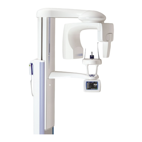
Planmeca ProMax X-ray Instruction Manual (346 pages)
with Dimax3
Brand:
Planmeca
| Category:
Medical Equipment
| Size: 17.16 MB
Table of Contents
Table of Contents
3
Chapter a GENERAL & TECHNICAL DATA
9
Warnings and Cautions
9
Manual Versions
10
Symbols
10
Technical Specifications
11
User's Statement for Promax X-Ray
13
Handling Precautions for Pcb's and Software Chips
20
Handling Printed Circuit Boards
20
Handling Software Flash Memory Chips
20
Emc Information
21
Chapter B INFORMATION DISPLAYS
25
General about Information Displays
25
Contents of the Information Displays
26
User Preference Settings
28
Setting Date and Time
28
Audio Settings
30
Behavioural Preferences
32
Visual Adjustments
33
Language Select
35
Default Program Settings
36
Feature Program Control
37
Enable / Disable Features
37
Special Functions
39
Special Operation Mode Selection
39
Error History
40
Exposure Statistics
41
Taking a Test Exposure
41
Beam Check
42
Network Settings
42
Service Settings
46
Special Operation Mode Selection
47
Preheat Calibration
48
Maximum Height
48
Exposure Program Tuning
49
Factory Default Settings
50
Configuration Selftest
50
Patient Support Alignment
51
GUI Software Update
52
Technical Calibrations
53
Collimator Assembly Screws Visible
54
Demo "Dancing Promax
57
Troubleshooting
59
Dimax Communication
60
Network Status
61
Entering the Password
62
Chapter C ERROR MESSAGES
63
Help and Error Message Short-Form Tables
63
Help and Error Message Main Categories
63
Help Messages (1Xx
64
Motorized Motion Related Errors (2Xx
65
X-Ray Generation Related Errors (3Xx
69
Feedback Errors (4Xx
71
Power Supply Related Errors (5Xx
73
Communication Errors (6Xx
73
Calibration Errors (7Xx
75
System Conflicts (8Xx
76
Infrastructure Errors (9Xx
78
Chapter D PREVENTIVE MAINTENANCE
81
System Maintenance
81
Cleaning
81
Operator's Checks
81
Preventive Maintenance Checks
82
General
82
X-Ray Tube Feedback System
82
Mechanical Checks
85
Column Motor Nut
85
Chapter E C-ARM and IMAGING ARM
87
Panoramic Beam and Patient Positioning Mechanism Adjustment
87
Required Tools
87
Checking the Panoramic Beam Position
90
Adjusting the Sensor Head Angle
93
Primary Collimator Angle Adjustment
95
Panoramic Beam Adjustment
96
X-Ray Unit with Fixed Primary Collimator - Primary Collimator Adjustment
100
Beam Check
104
Calibrating Panoramic Sensor Head
108
Checking the Adjustments
117
Patient Positioning Mechanism Adjustment
119
Additional Adjustment Method to Check the Eccentricity of the Rotation Movement: Reference Axis Mode
130
Additional Adjustment Method of the Patient Support Alignment
138
Other Adjustments and Calibrations
142
Calibration of Angle Sensors
142
Calibrating the Elbow Arm and C-Arm Gear Ratios
149
Adjustment of Tomo Mode Patient Positioning Lights
151
Calibrating the Panoramic Dynamic Exposure Control (DEC
164
Removing the Covers
171
C-Arm Upper Covers
171
Removing the Fixed Sensor Head Holder Covers
172
Removing the Movable Sensor Head Holder Covers
174
Removed by Pulling It from Its Position
174
Connector
174
C-Arm Inner Cover
175
Figure 135
175
Tube Head Covers
176
Figure 136
176
Shoulder Arm Covers
178
Replacing the Sensor Head
180
Attaching and Removing the Fixed Sensor Head
180
Sensor Head with Quick Connector Mechanism
184
REPLACING Pcbs
187
C-Arm PCB
187
Replacing Tube Head
189
Chapter F PATIENT SUPPORT ARM
191
Adjustments
191
Patient Positioning Mechanism Adjustment
191
Panoramic Mode Patient Positioning Lights
191
Removing the Covers
197
Patient Support Table Cover
197
Support Arm Lower Cover
198
Replacing the Gui Software
200
GUI Software Update, Only for Colour GUI
200
Replacing GUI Software Chip, Only for Black/White GUI
201
Replacing Pcbs
202
Patient Position Control PCB
202
Graphic User Interface (GUI) PCB
203
Chapter G COLUMN
207
Adjustments
207
Frankfort Plane Positioning Light
207
Adjusting the Telescopic Column Position
209
Calibrating the Column Motor Position Sensor
211
Removing the Covers
215
Removing the Telescopic Column Upper Front Panel
215
Removing the Telescopic Column Rear Cover Plates
217
Replacing the Column Motor
218
Replacing the Motor
218
Replacing the Lift Nut Assembly
225
Replacing/Upgrading Software
232
Replacing the CPU PCB Software Chips (Alternative 1
232
Loading the Software from a Computer (Alternative 2
234
Replacing the Battery on the Rtc Pcb
236
Replacing Pcbs
237
Power PCB
237
ETHERNET PCB and CPU PCB
242
Input PCB
243
Chapter H CEPHALOSTAT
245
Adjustments and Calibrations
245
Required Tools
245
Preparations before Adjustments
247
Checking and Adjusting the Sensor Head and Second Primary Collimator Mutual Position
247
Adjusting the Sensor and Second Primary Collimator Rails
249
Adjusting the Sensor Head Connector and Sensor Head Positions
250
Adjusting the Height of the Cephalostat
254
Checking the Cephalostat Head Support Position
257
Cephalostat Head Support Position Adjustment
259
Calibrating the C-Arm Position
262
Synchronizing the Scanning Mechanism and First Primary Collimator
265
Adjusting the Cephalometric Beam Vertical Position
267
Checking the Second Primary Collimator Position
270
Adjusting the Second Primary Collimator Position
273
Beam Check
277
Calibrating the Cephalostat Sensor Head
282
Calibrating the Cephalometric DEC
290
Checking the Adjustment
296
Removing and Attaching the Second Primary Collimator
297
Attaching the Second Primary Collimator Covers
298
Detaching and Attaching the Sensor Head
299
Cephalostat with Movable Sensor Head
299
Cephalostat with Fixed Sensor Head - Removing and Attaching the Sensor Head
303
Removing the Housings and Covers
306
Removing the Housings of the Head Support
306
Replacing Pcbs
309
Cephalostat Connector PCB
309
Chapter I DIAGRAMS
312
Advertisement
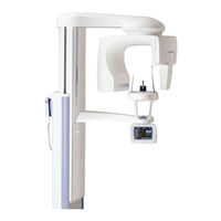
Planmeca ProMax X-ray User Manual (116 pages)
with Dimax3
Brand:
Planmeca
| Category:
Medical Equipment
| Size: 10.96 MB
Table of Contents
Table of Contents
3
Introduction
5
Unit Symbols
6
Warnings and Precautions
7
Digital Promax X-Ray System - Main Parts
9
Switching the Unit on
13
Programs
14
Panoramic Exposure Programs
15
Standard Panoramic Exposure Program
15
Advanced Panoramic Exposure Programs
16
Temporomandibular Joint (TMJ) Exposure Programs
18
Standard TMJ Programs
18
Advanced TMJ Programs
20
Sinus Exposure Programs
21
Standard Sinus Exposure Program
21
Advanced Sinus Exposure Programs
22
Tomographic Exposure Programs
24
Jaw Shape and Size in Tomography Exposure
29
Preparations for the Exposure
33
Moving the Sensor Head from Cephalostat to C-Arm
33
Preparing the Patient
35
Patient Positioning Controls
36
Control Panel
38
General Settings
38
Selecting Kilovolt and Milliampere Values
38
Programming Quick Button Values
39
Selecting Patient Entry Position
40
Selecting Patient Size
40
Selecting Panoramic Exposure Program
41
Selecting Segmentation (Optional)
43
Selecting Jaw Shape & Size
44
Selecting Temporomandibular Joint (TMJ) Exposure Program
45
Selecting Jaw Size
46
Adjusting Position and Imaging Angle
47
Selecting Sinus Exposure Program
48
Selecting Tomographic (Tomo) Exposure Program
50
Selecting Target Area
53
Information Displays
55
User Preference Settings
55
Feature Program Control
62
Special Functions
64
DYNAMIC EXPOSURE CONTROL (Optional)
67
Using the DEC Function
67
Setting the DEC Density
68
Panoramic Exposure
69
Patient Positioning
70
Taking an Exposure
75
Temporomandibular Joint (Tmj) Exposure
77
Double TMJ Exposure (Lateral, PA or Lateral-PA)
77
First Exposure - Jaw Closed
77
Second Exposure - Jaw Open
84
Multi-Angle TMJ Exposure (PA or Lat)
85
Patient Positioning
86
Taking an Exposure
88
Sinus Exposure
90
Patient Positioning
91
Taking an Exposure
94
Tomographic Exposure
95
Patient Positioning
97
Adjusting the Position of the Target Area
100
Taking an Exposure
103
Cleaning
106
Service
106
Disposal of the Unit
107
Help Messages
108
Technical Specifications
109
Technical Data
109
Panoramic X-Ray Field Area on Image Sensor
110
Dimensions
111
Minimum Operational Space Requirements
112
Connecting the Exposure Switch Cable
112
Ethernet Link Configuration
113
Connecting the External Control Panel Cable (Optional)
114
Disconnecting Cables
114
Advertisement
Related Products
Planmeca ProMax
Planmeca ProMax Pan/Ceph
Planmeca ProX
Planmeca ProOne
Planmeca ProSensor HD
Planmeca Prostyle Intra
Planmeca Proline XC Pan
Planmeca Proline EC ceph
Planmeca Proline EC pan
Planmeca Proline EC Panoramic
Planmeca Categories
Medical Equipment
Dental equipment
Pet Care Product
3D Printers
Recording Equipment
More Planmeca Manuals
Login
Sign In
OR
Sign in with Facebook
Sign in with Google
Upload manual
Upload from disk
Upload from URL