Sign In
Upload
Manuals
Brands
Keysight Manuals
Measuring Instruments
N9923A
Keysight N9923A Manuals
Manuals and User Guides for Keysight N9923A. We have
3
Keysight N9923A manuals available for free PDF download: User Manual, Service Manual
Keysight N9923A User Manual (276 pages)
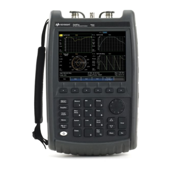
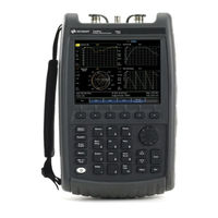
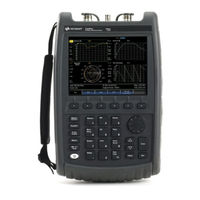
FieldFox RF Network Analyzers
Brand:
Keysight
| Category:
Measuring Instruments
| Size: 3.89 MB
Table of Contents
Safety Notices
2
Table of Contents
5
Overview
15
Options and Features
15
Accessories
17
Fieldfox Manuals, Software, and Supplemental Help
18
Conventions that Are Used in the Manual
18
Safety Notes
19
Preparing for Initial Use of Your New Fieldfox
21
Check the Shipment
21
Meeting Power Requirements for the AC/DC Adapter
21
Install the Lithium-Ion Battery
22
Battery Usage
22
Fieldfox ON/OFF Settings
23
To Conserve Battery Power
23
Power Button LED Status
24
Fieldfox High Temperature Protection
24
How to Monitor the Internal Fieldfox Temperature
24
Temperature Control Mode
25
High-Temp Shut down
25
Avoid Overpowering the Fieldfox
25
Take the Fieldfox Tour
27
Front Panel
27
Top Panel
30
Side Panel
30
Screen Tour
32
How to Enter Numeric Values
34
Multiplier Abbreviations
34
Connector Care
35
NA (Network Analyzer) Mode
37
NA Mode Settings
39
About S-Parameters
39
Mixed-Mode S-Parameters
40
Parameter Conversion
41
Receiver Measurements
42
Multi-Trace Configurations
43
Quick Settings
45
Calibration Settings
46
Format
46
Frequency Range
47
Scale Settings
48
Magnitude Offset
49
Electrical Delay
49
Phase Offset
50
Averaging
50
IF Bandwidth
51
Smoothing
51
Single or Continuous Measure
52
Resolution (Number of Data Points)
52
Sweep Time
53
Output Power
53
System Impedance (Z0)
54
Port Extensions
54
Velocity Factor
56
Big Marker Display States (a and B)
56
Increase Dynamic Range
58
Time Domain - Option 010
62
Overview
63
Chapter 3 , “NA (Network Analyzer) Mode”, on Page 37
64
Time Domain (Transform) Settings
64
Transform Settings Table
64
Frequency Range and Points
64
Stimulus (Mode)
65
Set Frequency Lowpass
65
Start/Stop Time
65
Distance Units
66
Window Layout
66
Transform Window
66
Window Settings
67
Line Loss and Velocity Factor
69
Data Chain
70
Trace Settings
71
Transform Enable
71
Gate Enable
71
Gating
72
How to Make Time Domain Gating Settings
73
Start, Stop, Center, and Span Gate Times
73
Gating Type
73
CAT (Cable and Antenna Test) Mode
75
CAT Mode Settings
77
How to Select CAT Mode
77
Measurement Selection
77
Quick Settings Table
78
Frequency Range
79
Scale Settings
79
Averaging
80
Smoothing
81
Single or Continuous Measure
81
Resolution (Number of Data Points)
82
Sweep Time
82
Output Power
83
Coupled Frequency
84
Interference Rejection
85
Return Loss Measurements
86
How to Measure Return Loss
86
1-Port Cable Loss Measurements
86
How to Make a 1-Port Cable Loss Measurement
87
2-Port Insertion Loss Measurements
88
How to Make a 2-Port Insertion Loss Measurement
88
Chapter 6 DTF (Distance to Fault) Measurements
89
How to Make DTF Measurements
90
DTF Measurement Settings
91
DTF Settings Table
91
DTF Measurement (Format)
91
DTF Start and Stop Distance
92
Frequency Mode
92
Coupled Frequency
93
Cable (Correction) Specifications
94
Window Settings
97
DTF Units
98
Calculated DTF Values
98
About Alias Faults
98
Chapter 7, "Calibration for NA, CAT, and VVM Modes
101
Calibration for NA, CAT, and VVM Modes
103
Why and When to Calibrate
103
Definitions
103
Calready
104
How to Perform a Calibration
104
Quickcal (Option 112)
106
Mechanical Cal
108
Ecal
110
Simple Response Cals
112
View Cal
114
Calibration Type
114
Isolation Step of a 2-Port Cal
117
Waveguide Calibrations
117
Enhanced Response Optimization
119
Interpolation
119
Cal on ? - Questionable Accuracy
120
Compatible Mode Calibrations
120
Save the Calibration
120
Calready Properties
120
Verifying Calibration and Jumper Cable Integrity
122
Verify a Calibration
122
Test the Jumper Cable
122
Calibration Method Summary
123
Power Meter (USB) Mode
126
Supported Power Sensors
127
How to Connect the Power Sensor
127
USB Power Meter Settings
128
How to Select Power Meter Mode
128
Average / Peak
128
Zeroing
128
Frequency
129
Source Control
129
Relative and Offset Power Measurements
131
Display Units
131
Resolution
132
Averaging
132
Single or Continuous Measure
132
Step Detection Mode
133
Limits
133
Frequency Offset Using Power Sensor (FOPS) - Option 208 Overview
137
FOPS Settings
139
How to Select Power Meter (USB Sensor)
139
Measurement Selection
139
Sweep Type and Frequency
140
Power Sensor Settling
142
Sweep Settings
142
Amplitude Markers
143
Trace Math
143
Pulse Measurements Mode - Option
145
Supported Power Sensors
147
Switching between Pulse Measurement Mode and Power Meter Mode
147
How to Connect the Power Sensor
147
Pulse Measurement Settings
148
How to Select Pulse Measurement Mode
148
Measurement Selection
148
Frequency / Time
148
Zoom Window
149
Scale
150
Averaging
150
Video Bandwidth
151
Single or Continuous Measure
151
Resolution
152
Triggering
152
Marker Settings
155
Amplitude Markers
155
Marker Search
156
Auto Analysis
157
Pulse Top
158
Grid
158
Trace Memory
158
VVM (Vector Voltmeter) Mode - Option
161
Overview
163
VVM Mode Settings
164
How to Select VVM Mode
164
Measurement Selection
164
Frequency Selection
164
Display Resolution
164
IF Bandwidth
165
Output Power
165
Averaging
166
Single or Continuous Measure
166
VVM Calibration
167
Zeroing
167
1-Port Cable Trimming Measurements
169
How to Make a 1-Port Cable Trimming Measurement
169
2-Port Transmission Measurements
171
How to Make a 2-Port Transmission Measurement
171
A/B and B/A Measurements
172
Data Analysis Features
174
All about Markers
174
How to Create Markers
174
How to Move a Marker after It Is Created
174
About Delta Markers
175
Marker Table
176
Coupled Markers
176
Marker Colors
177
Marker Trace
177
Marker Format
178
Searching with Markers
179
What Is a 'Peak
182
Marker Functions
183
All about Limit Lines
185
How to Create Fixed Limit Lines
185
Relative Limit Lines
186
Build from Trace
187
Limit Options
187
How to Save and Recall Limits
188
All about Trace Math
189
How to Display Data and Memory Traces
189
How to Perform Trace Math
189
About Math Operations
190
13 File Management
191
Saving and Recalling Files
192
Save Files
192
Recall Files
195
Move (Copy) Files
195
Set File Type and Select Device
196
Manage Files
199
Manage Folders
200
Edit Keywords
201
Prefixes and Suffixes for Filenames
202
Printing
205
How to Print the Current Screen or a Saved File
205
System Settings Run/Hold
208
How to Perform a Single Sweep While in Hold
208
Preset
209
How to Preset the Fieldfox
209
User Preset
209
How to Set User Preset
209
How to Recall User Preset
209
Audio (Volume) Control
210
How to Set Fieldfox Volume Control
210
Display Settings
211
Display Brightness
211
Display Colors
211
Trace Width
212
Title
212
Edit Keywords
213
Full Screen Mode
213
Preferences
213
Quick Settings Table
213
Save and Reset Preferences
214
Global Settings (Overview)
215
Language
215
Battery Saver
216
Startup Mode
217
Display
217
Audio
218
Date and Time
218
Gps
219
File Folders
220
System Configuration
222
Options (Licensing)
222
Gps
223
Frequency Reference Source
226
Security Level
227
Date and Time, Format, and Time Zone Settings
227
LAN Settings
229
Power on
230
LAN Settings
231
How to Configure LAN Settings
231
Power on
232
How to Set Power on
232
Fieldfox Package Installer (Applies to N9912A Units with Serial Number Prefixes ≥5607)
233
How to Run the Installer
233
How to Backup Files
233
How to Restore Files
234
Service Diagnostics
235
System Information
235
Using the Mini-USB Port to Send SCPI Commands and Queries (Applies to N9912A Units with Serial Number Prefixes ≥5607 Only)
237
Mini-USB Connection to PC with IO Libraries
237
Working with the Lithium-Ion Battery Viewing the Battery Charge Status
239
See also
239
Viewing the Battery Charge Status
239
Service Diagnostics-Battery Screen
240
Built-In Battery Gauge
240
Charging the Battery
241
Internal Charging with the AC/DC Adapter
241
Using the External Battery Charger (N9910X-872)
243
Reconditioning Battery
244
Battery Care
244
Maximizing Battery Life
244
Lithium-Ion Battery Disposal
245
17 Safety Considerations
247
For the Fieldfox
248
For the AC/DC Adapter
250
For the External Battery Charger (N9910X-872)
251
For the Battery
251
Battery Protective Functions
252
Active Protection
253
Passive Protection
254
Batteries: Safe Handling and Disposal
254
Environmental Requirements
254
Electrical Requirements
254
Electrostatic Discharge (ESD) Precautions
255
Fieldfox Markings
256
Battery Markings
257
Packaging Markings
258
AC/DC Adapter Markings
258
Certification and Compliance Statements
259
Certification
259
Manufacturer's Declaration
259
Declaration of Conformity
259
Emc
260
Safety
260
South Korean Class B EMC Declaration
260
Acoustic Statement (European Machinery Directive)
260
A:.connector Care Review
261
B:.specifications/Data Sheet
263
C:.instrument Calibration
265
How Often Should I Calibrate My Instrument
265
How Do I Get an Instrument Calibration
265
What Are My Choices of Instrument Calibration
266
D:.korean Battery Safety Translation
267
Advertisement
Keysight N9923A User Manual (167 pages)
Brand:
Keysight
| Category:
Measuring Instruments
| Size: 2.74 MB
Table of Contents
Table of Contents
4
A.07.75 Firmware Release Updates
7
Overview
8
Options and Features
8
Accessories
9
Fieldfox Manuals, Software, and Supplemental Help
9
Preparing for Initial Use of Your New Fieldfox
11
Check the Shipment
11
Meeting Power Requirements for the AC/DC Adapter
11
Install the Lithium-Ion Battery
12
Fieldfox ON/OFF Settings
13
Fieldfox High-Temperature Protection
14
Avoid Overpowering the Fieldfox
14
Take the Fieldfox Tour
15
How to Enter Numeric Values
19
Na (Network Analyzer) Mode
20
How to Measure S-Parameters
21
NA Mode Settings
21
Mixed-Mode Measurements
22
Parameter Conversion
22
Multi-Trace Configurations
23
Receiver Measurements
23
Quick Settings
25
Calibration Settings
26
Format
26
Frequency Range
27
Scale Settings
27
Electrical Delay
28
Phase Offset
28
Averaging
29
IF Bandwidth
29
Resolution (Number of Points)
30
Single/Continuous
30
Smoothing
30
Output Power
31
Sweep Time
31
Port Extensions
32
System Impedance
32
Velocity Factor
33
Increase Dynamic Range
35
Time Domain - Option 010
36
Time Domain (Transform) Settings
37
Transform Settings Table
37
Frequency Range and Points
38
Set Frequency Lowpass
38
Start/Stop Time
38
Stimulus (Mode)
38
Distance Units
39
Transform Window
39
Window Layout
39
Data Chain
40
Line Loss and Velocity Factor
40
Trace Settings
40
Gating
41
Gating Enable
41
Transform Enable
41
Gating Type
42
Start, Stop, Center, and Span Gate Times
42
Cat (Cable and Antenna Test) Mode - Option 305
44
CAT Mode Settings
45
Measurement Selection
45
Frequency Range
46
Quick Settings
46
Averaging
47
Scale Settings
47
Resolution
48
Single/Continuous
48
Output Power
49
Sweep Time
49
Coupled Frequency
50
Interference Rejection
50
1 Port Cable Loss Measurement
51
Return Loss Measurement
51
1 Port Cable Loss Measurements
51
Return Loss Measurements
51
2 Port Insertion Loss Measurement
52
2 Port Insertion Loss Measurements
52
Dtf (Distance to Fault) Measurements
54
Distance to Fault Measurements
54
How to Make DTF Measurements
54
DTF Measurement (Format)
55
DTF Measurement Settings
55
DTF Settings Table
55
DTF Start and Stop Distance
55
Frequency Mode
56
Cable (Correction) Specifications
57
Coupled Frequency
57
Calculated DTF Values
60
DTF Units
60
Window Settings
60
About Alias Faults
61
Calibration for Na, Cat, and VVM Modes
62
All about Calibration
62
Why and When to Calibrate
62
Calready
63
Definitions
63
How to Perform a Calibration
63
Quickcal
64
Mechanical Cal
66
Ecal
68
Simple Response Cal
69
View Cal
70
Calibration Type
71
Isolation Step of a 2-Port Cal
72
Waveguide Calibrations
73
Enhanced Response Optimization
74
Calready Properties
75
Compatible Mode Calibrations
75
Interpolation
75
Questionable Accuracy
75
Save a Calibration
75
Verify Calibration
76
Verifying Calibration and Jumper Cable Integrity
76
Calibration Method Summary
77
Frequency Offset Using Power Sensor (Fops) - Option 208
85
Overview
86
Measurement Selection
87
Sweep Type and Frequency
87
Power Sensor Settling
89
Sweep Settings
89
Amplitude Markers
90
Pulse Measurements Mode - Option 330
91
Measurement Selection
92
Supported Power Sensors
92
Frequency / Time
93
Zoom Window
93
Scale
94
Averaging
95
Single or Continuous Measure
95
Video Bandwidth
95
Resolution
96
Triggering
96
Amplitude Markers
98
Marker Settings
98
Pulse Timing Diagram
98
Auto Analysis
99
Marker Search
99
Grid
100
Pulse Top
100
Trace Memory
101
Data Analysis Features
110
All about Markers
110
About Delta Markers
111
Marker Table
112
Coupled Markers
112
Marker Colors
113
Marker Trace
113
Marker Format
114
Searching with Markers
114
What Is a 'Peak
117
Optional Settings Markers
110
Set Markers
110
All about Limit Lines
118
Relative Limit Lines
120
Build from Trace
120
Limit Options
121
How to Save and Recall Limits
121
Limit Lines
118
Marker Functions
118
Use Limit Lines
118
All about Trace Math
122
About Math Operations
123
Trace Math
122
Use Trace Math
122
File Management
124
Save Files
124
Save Measurement Settings and Results
124
Recall Files
125
Set File Type and Device
126
Manage Files
128
Manage Folders
128
Edit Keywords
129
Prefixes for Filenames
129
Printing
130
System Settings
131
Run/Hold
131
Preset
132
User Preset
132
Volume Control
132
Display Settings
133
Colors
133
Brightness
134
Trace Width
134
Title
135
Edit Keywords
135
Full Screen Mode
135
Preferences
135
Quick Settings Table
135
Save and Reset Preferences
136
Language
136
Startup Mode
137
Battery Saver
137
System Configuration Options (Licensing)
138
Gps
139
Frequency Reference Source
140
Security Level
141
Date and Time Settings
142
LAN Settings
143
Power on
144
Service Diagnostics
144
See also Erase User Data
145
Erase User Data
145
See also
146
Keysight N9923A Service Manual (138 pages)
FieldFox RF Vector Network Analyzer
Brand:
Keysight
| Category:
Measuring Instruments
| Size: 4.31 MB
Table of Contents
Safety Notices
2
Table of Contents
4
1 Safety and Regulatory Information
8
Information in this Chapter
8
Chapter One At-A-Glance
8
Safety Symbols
9
General Safety Considerations
10
Safety Earth Ground
10
Before Applying Power
10
Servicing
10
Electrostatic Discharge Protection
12
Regulatory Information
14
Instrument Markings
14
Battery Disposal
15
2 General Product Information
16
Information in this Chapter
16
Chapter Two At-A-Glance
16
Maintenance
17
Physical Maintenance
17
Electrical Maintenance
17
Analyzer Options
18
Frequency Range Options
18
Network Analyzer (NA) Options
18
Power Meter (PM) Option
18
Cable and Antenna Test (CAT) Option
18
Vector Voltmeter (VVM) Option
19
Keysight Support, Services, and Assistance
20
Service and Support Options
20
Calibration Options
20
Contacting Keysight
21
Shipping Your Analyzer to Keysight for Service or Repair
21
Printing Copies of Documentation from the Web
21
3 Tests and Adjustments
24
Information in this Chapter
24
Chapter Three At-A-Glance
24
Before You Begin
25
Protect against Electrostatic Discharge (ESD)
25
Allow the Analyzer to Warm up
25
Review the Principles of Connector Care
25
Service Test Equipment
27
Before Returning an Instrument to a Customer
28
Operational Check
29
Performance Tests and Adjustments
30
Performance Tests
30
Adjustments
31
Test Software and Information Available on the Web
32
TME Downloads
32
Keysight Fieldfox Customer Support Web Pages
32
4 Troubleshooting
34
Information in this Chapter
34
Chapter Four At-A-Glance
34
Protect against Electrostatic Discharge (ESD)
35
Assembly Replacement Sequence
36
Getting Started with Troubleshooting
37
Check the Basics
37
Troubleshooting Organization
37
Power up Troubleshooting
39
Front Panel Group Troubleshooting
40
Measurement Group Troubleshooting
41
5 Theory of Operation
42
Information in this Chapter
42
Chapter Five At-A-Glance
42
Analyzer System Operation
43
Functional Groups of the Analyzer
43
Front Panel Group
45
A3 Front Panel Interface Board
45
A2 LCD Assembly
46
Measurement Group
47
A4 RF Board
47
A5 System Board
51
A6 SOM Board
55
Main Battery
55
Grounding and Power
56
Grounding
56
Voltages and Power Supplies
56
Power Control and Management
57
Battery Related Information
58
Operation in Modes
60
CAT, NA, and VMM Modes
61
Power Meter Mode
61
Temperature Related Information
62
User Calibration in CAT and NA Modes
63
Factory Calibration
63
Quickcal
64
User Calibration
64
Firmware Related Information
65
General Description
65
User Accessible Files
65
Operational Files
65
Erase User Data Utility
66
Error Log
66
Firmware Upgrades
66
LAN Interface
67
6 Replaceable Parts
68
Information in this Chapter
68
Chapter Six At-A-Glance
68
Ordering Information
69
Assembly Replacement Procedure
70
Replaceable Parts Listings
71
Entire Analyzer
71
Front Panel Group
71
Measurement Group
71
Case Group
71
Miscellaneous Parts
79
7 Repair and Replacement Procedures
82
Information in this Chapter
82
Chapter Seven At-A-Glance
82
Personal Safety Warnings
83
Safety Earth Ground
83
Electrostatic Discharge (ESD) Protection
84
Assembly Replacement Sequence
85
Removal and Replacement Procedures
86
Removing and Replacing the Main Battery
87
Removing and Replacing the Case Group Parts
88
Removing and Replacing the Front Panel Group Assemblies
102
Removing and Replacing the Measurement Group Assemblies
109
Post-Repair Procedures
124
Manual Checks and Procedures
124
8 General Purpose Maintenance and Service Procedures
126
Information in this Chapter
126
Chapter Eight At-A-Glance
126
Supplemental Information
127
Service Related User Operations
128
To View Currently Installed Options
128
To View the Current Firmware Revision, Etc
128
To View the Error Log
128
To View Temperature Readings
128
Erase User Data Utility
129
Options
130
To View Currently Installed Options
130
Re-Installing Options
130
Firmware Upgrades
132
To Check the Current Firmware Revision
132
Miscellaneous Service and Maintenance
133
Cleaning the Display
133
Battery Maintenance
133
Advertisement
Advertisement
Related Products
Keysight N9925A
Keysight N9926A
Keysight N9927A
Keysight N9928A
Keysight N9915A
Keysight N9917A
Keysight N9918A
Keysight N9950A
Keysight N9960A
Keysight N9961A
Keysight Categories
Measuring Instruments
Test Equipment
Multimeter
Control Unit
Portable Generator
More Keysight Manuals
Login
Sign In
OR
Sign in with Facebook
Sign in with Google
Upload manual
Upload from disk
Upload from URL