Sign In
Upload
Manuals
Brands
Eaton Manuals
Industrial Equipment
Rapid Link RASP5
Eaton Rapid Link RASP5 Manuals
Manuals and User Guides for Eaton Rapid Link RASP5. We have
2
Eaton Rapid Link RASP5 manuals available for free PDF download: Manual
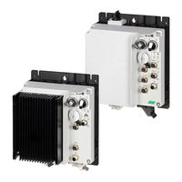
Eaton Rapid Link RASP5 Manual (249 pages)
Brand:
Eaton
| Category:
Industrial Equipment
| Size: 10.94 MB
Table of Contents
Table of Contents
5
About this Manual
11
Application Notes
11
List of Revisions
11
Hints
12
Safety Warning Concerning Personal Injury Hazards
12
Safety Warning Concerning Property Damage
12
Writing Conventions
12
Abbreviations and Symbols
13
Documents with Additional Information
14
Units of Measurement
14
1 Rapid Link 5 System
15
System Overview
16
Checking the Delivery
18
Rating Data on the Nameplate
19
RAMO5 Type Key
21
RASP5 Type Key
22
Technical Data
23
Compliance with UL Standards
26
Excerpts Concerning UL Conformity
26
Ramo5
29
Rasp5
30
Selection Criteria
32
Special Features of Motor Selection for RASP5
33
Synchronous, Reluctance, and PM Motors
33
Proper Use
34
Designated Power Supply Systems
34
Machinery Directive and CE Mark
35
Maintenance and Inspection
36
Storage
37
Service and Warranty
37
2 Engineering
39
Rapid Link 5 Modules
39
Versions
40
Connections
41
Connections in the Power Section
43
Repair Switches
45
Electrical Power Network
47
Mains Connection and Configuration
47
Mains Voltage and Frequency
47
Voltage Balance
48
Safety and Protection
49
Fuses and Cable Cross-Sections
49
Residual Current Devices
50
Power Bus
51
EMC-Compliant Installation for RASP5
53
Safe Torque off (STO)
54
Overview
54
Safe Stop and Preventing a Restart
55
TÜV Certification
56
STO-Compatible Installation
57
Direct Enable
60
STO Function Pick-Up Time
61
STO Function Messages
61
Error Messages
61
STO Function Checklist
62
Regular Maintenance
63
Application of the STO Function and Safety Parameters
64
Sensor Inputs
65
Actuator Output
70
Device Fan Connection
71
Motor and Application
73
Motor Selection
73
Motor and Circuit Type
73
Direction Reversal
74
Quick Stop
75
Interlocked Manual Operation
76
External Brake
78
Regenerative Braking
81
Thermistor and Motor Cable Monitoring
83
3 Installation
85
Introduction
85
Instruction Leaflets
85
Mounting Position
86
Clearances
87
Attachment
88
Position of the Power Connections
91
Electrical Installation
94
Power Bus
94
Flexible Busbar (RA-C1-7
95
Round Cable
98
Power Plug
101
Ramo5
101
Rasp5
105
Motor Feeder
109
Motor Feeder Plug
109
Motor Feeder Connection Examples
110
RASP5 Motor Feeder
113
Screened Motor Cable for RASP5
114
Isolation Test
117
4 Operation
119
Commissioning Checklist
119
Operational Warnings
120
Specific Hazard Warnings for RASP5
121
Manual Control
123
5 RAMO5 Motor Starter
125
Designation
125
Features
126
Connections
127
Specific Technical Data
128
Block Diagrams
129
LED Indicators
131
Configure Specialist Settings
133
Commissioning
133
Set the Rated Motor Current (P1-08)
134
Sensor Inputs
135
Quick Stop and Interlocked Manual Mode
136
Phase Change
137
Monitoring the Low Current Limit
138
Quick Stop
138
6 RASP5 Speed Controller
139
Designation
139
Features
140
Connections
141
Specific Technical Data
142
Overload Capacity
144
Derating Curves
145
Block Diagram
146
LED Indicators
148
Configuration of Specific Settings
150
Commissioning
150
Set the Rated Motor Current (P1-08)
151
Sensor Inputs
152
Quick Stop and Interlocked Manual Operation
153
Phase Change
156
Motor Cable Monitoring
156
Stop Behavior
157
7 Parameterization
159
Configuration Using the Drivesconnect Software
162
Parameterization Using OLED Operating Unit
164
DX-KEY-OLED Operating Unit Elements
165
Set Parameters
166
Reset Parameters (RESET)
167
Extended Parameter Set
167
Configure Parameters Using an App
168
8 Parameter List
169
Parameter Groups
169
Menu Structure
170
Parameter Groups for RAMO5
170
Parameter Group 0 (Monitor)
170
Parameter Group 1 (Basic)
173
Parameter Group 2 (Extended Functions)
174
Parameter Group 3 (Mechanical Brake and Digital Inputs)
176
Parameter Group 5 (Communication)
177
Parameter Group 6 (Extended Motor Control)
178
Parameter Groups for RASP5
179
Parameter Group 0 (Monitor)
179
Parameter Group 1 (Basic)
183
Parameter Group 2 (Extended Functions)
185
Parameter Group 3 (Mechanical Brake and Digital Inputs)
189
Parameter Group 4 (Brake Chopper and DC Brake)
190
Parameter Group 5 (Communication)
191
Parameter Group 6 (Extended Motor Control)
193
Parameter Group 7 (Motor)
195
9 Communication
197
AS-Interface
197
As-I Led
197
Data Cable
198
Asi Profile
198
Gateway
199
Cable Length
199
Addressing
199
Replacing Rapid Link Devices in the Asi Circuit
200
Asi Ribbon Cable
200
External Quick Stop (for RASP5)
201
Extension Cable
201
Cable Routing
202
Controlling RAMO5 Via the AS-Interface
203
Controlling RASP5 Via the AS-Interface
204
Diagnostics and Troubleshooting Via the AS-Interface
205
Ethernet / IP
206
Introduction
207
Proper Use
208
Ethernet/Ip Interface of the Rapid Link 5 Module
209
LED Indicators for Ethernet/Ip
210
Integrating Rapid Link 5 into an Ethernet/Ip Network
212
Installation Instructions
213
EDS File
214
Configuration
215
Configuring the IP Address
217
External 24 V DC Control Voltage
220
General Design Data of the Ethernet/Ip Interface
223
Commissioning
224
Cyclic Data
225
Acyclic Data
231
Acyclic Parameters
232
10 Error Messages
239
Introduction
239
Trip Log
239
Acknowledge Fault (Reset)
239
Automatic Reset
239
Error Messages
240
RAMO5 Error Messages
240
RASP5 Error Messages
242
Index
247
Advertisement
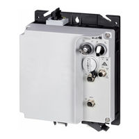
Eaton Rapid Link RASP5 Manual (218 pages)
For Rapid Link 5
Brand:
Eaton
| Category:
Control Systems
| Size: 9.75 MB
Table of Contents
Table of Contents
5
About this Manual
11
List of Revisions
11
User Note
11
Safety Warning Concerning Personal Injury Hazards
12
Safety Warning Concerning Property Damage
12
Tips
12
Writing Conventions
12
Abbreviations and Symbols
13
Documents with Additional Information
14
Units of Measurement
14
1 Rapid Link System 5
15
System Overview
16
Checking the Delivery
18
Rated Operational Data on the Nameplate
19
Type Code RAMO5
21
Type Code RASP5
22
Technical Data
23
UL Standards Compliance
26
Ramo5
26
Rasp5
27
Selection Criteria
29
Special Features of the Motor Selection for RASP5
30
Synchronous, Reluctance, and PM Motors
30
Proper Use
31
Designated Power Supply Systems
31
Machinery Safety Directive and CE Marking
32
Maintenance and Inspection
33
Storage
34
Service and Warranty
34
2 Engineering
35
Rapid Link Modules
35
Instance
36
Connections
37
Repair and Maintenance Switch
39
Power Terminals
41
Electrical Power Network
44
Mains Connection and Configuration
44
Mains Voltage and Frequency
44
Voltage Balance
45
Safety and Protection
46
Fuses and Cable Cross-Sections
46
Residual-Current Device (RCD)
47
Power Bus
48
EMC Compliant Installation for RASP5
50
STO Function
51
Overview
51
TÜV Certification
52
STO-Compatible Installation
53
Direct Release
56
STO Function Pick-Up Time
57
STO Function Checklist
57
Error Messages
57
STO Function Checklist
58
Regular Maintenance
59
Safe Stop" Function
59
Sensor Inputs I1 and I2
61
Actuator Output
65
Device Fan Connection
66
Motor and Application
68
Motor Selection
68
Motor and Circuit Type
68
Change of Rotation
69
Quick Stop
70
Interlocked Manual Operation
71
External Brake
73
Regenerative Braking
76
Thermistor and Motor Cable Monitoring
78
3 Installation
79
Introduction
79
Installation Instructions
79
Installation Site
79
Free Space
80
Mounting
81
Position of the Power Terminals
84
Electrical Installation
87
Power Bus
87
Flexible (RA-C1-7
88
Round Conductor
91
Power Plug
94
Ramo5
94
Rasp5
98
Motor Feeder
102
Motor Feeder Plug
102
Motor Feeder Connecting Examples
103
Motor Output for RASP5
106
Screened Motor Cable for RASP5
107
Isolation Test
110
4 Operation
111
Checklist for Commissioning
111
Operational Hazard Warnings
112
Specific Hazard Warnings for RAMO5
113
Specific Hazard Warnings for RASP5
118
Manual Control
120
5 RAMO5 Motor Starter
123
Description
123
Features
124
Connections
125
Special Technical Data
126
Block Diagrams
127
LED Displays
129
Configure Special Settings
131
Configure Set Rated Motor Current (P1-08)
131
Sensor Inputs I1 and I2
132
Quick Stop and Interlocked Manual Operation
133
Phase Change
134
Monitoring the Current Lower Limit
135
Quick Stop
135
6 RASP5 Speed Controller
137
Description
137
Features
138
Connections
139
Special Technical Data
140
Overload Capacity
142
Derating Curves
142
Block Diagram
144
LED Indicators
145
Configure Special Settings
147
Commissioning
147
Motor Cable Monitoring
148
Phase Change
151
Stop Behavior
151
7 Configuration
153
Parameterization Via Pc/App
153
Parameterization with PC and the Drivesconnect Software
154
8 PC Tool
155
Surface
155
Parameter Editor
156
9 Control Unit
159
Elements of the DX-KEY LED2 External Control Unit
160
Adjust Parameters
161
Resetting Parameters (RESET)
162
Extended Parameter Set
162
10 Parameter List
165
Parameter Groups
165
Menu Structure
166
Parameter Groups for RAMO
166
Monitor" Parameter Group 0
166
Parameter Group 1 ("Basic")
169
Parameter Group 2 ("Extended Functions")
170
Parameter Group 3 ("Mechanical Brake and Digital Inputs")
172
Parameter Group 5 ("Communication")
173
Parameter Group 6 ("Extended Motor Control")
175
Parameter P1-13
175
Parameter Groups for RASP
176
Monitor" Parameter Group 0
176
Parameter Group 1 ("Basic")
180
Parameter Group 2 ("Extended Functions")
182
Parameter Group 3 ("Mechanical Brake and Digital Inputs")
186
Parameter Group 4 ("Brake Chopper and DC Brake")
187
Parameter Group 5 ("Communication")
188
Parameter Group 6 ("Extended Motor Control")
190
Parameter Group 7 ("Motor")
192
Parameter P1-13
193
11 Communications
195
Asi Data Bus
195
Asi LED Display
195
Data Cable
196
Data Transfer
196
Gateway
197
Cable Length
197
Addressing
197
Replacing Rapid Link Devices in the AS-I Circuit
198
ASI Flat Cable
198
External Quick Stop
199
Extension Circuit
199
Cable Routing
200
RASP Actuation
201
Asi Control RAMO
202
Diagnostics and Troubleshooting Via AS-Interface
203
OP-Bus
204
Hardware
204
12 Error Messages
209
Introduction
209
Acknowledge Fault (Reset)
209
Automatic Reset
209
Error List
210
RAMO Error List
210
RASP Error List
212
Index
217
Advertisement
Related Products
Eaton Rapid Link RAMO5
Eaton RPR-2
Eaton RAMO5 EIP Series
Eaton RAMO5 PNT Series
Eaton Rapid Link 5
Eaton RAMO
Eaton RASP5 Series
Eaton RASP5 A Series
Eaton RAMO5 A Series
Eaton RASP 5
Eaton Categories
UPS
Circuit breakers
Industrial Equipment
Switch
Industrial Electrical
More Eaton Manuals
Login
Sign In
OR
Sign in with Facebook
Sign in with Google
Upload manual
Upload from disk
Upload from URL