Table of Contents
Advertisement
Quick Links
Advertisement
Table of Contents

Related Manuals for Eaton RAMO5


Summary of Contents for Eaton RAMO5
- Page 1 Manual 10/19 MN034004EN Rapid Link 5 RAMO5 RASP5...
- Page 2 The German-language edition of this document constitutes the original operating manual. Translation of the original operating manual 1. 2019 edition, publication date 10/19 © 2019 by Eaton Industries GmbH, 53105 Bonn Author: Mustafa Akel Editor: René Wiegand All rights, including those of translation, reserved.
- Page 3 Danger! Dangerous electrical voltage! Before commencing the installation • Disconnect the power supply of the device. • Wherever faults in the automation system may cause damage to persons or property, external measures must • Ensure that devices cannot be accidentally retriggered. be implemented to ensure a safe operating state in the event of a fault or malfunction (for example, by means of •...
-
Page 5: Table Of Contents
Repair and maintenance switch ........... 35 2.3.1 Power terminals ................37 Electrical power network ............. 40 2.4.1 Mains connection and configuration ..........40 2.4.2 Mains voltage and frequency ............40 2.4.3 Voltage balance ................41 Rapid Link 5 · RAMO5 · RASP5 10/19 MN034004EN www.eaton.com... - Page 6 Position of the power terminals........... 80 Electrical Installation ..............83 Power bus..................83 3.4.1 Flexible (RA-C1-7...) busbar............84 3.4.2 Round conductor ................. 87 Power plug................... 90 3.5.1 RAMO5 ..................90 3.5.2 RASP5..................94 Rapid Link 5 · RAMO5 · RASP5 10/19 MN034004EN www.eaton.com...
- Page 7 Derating curves ................138 Block diagram................140 LED Indicators................141 Configure special settings............143 6.7.1 Commissioning ................143 6.7.2 Motor cable monitoring..............144 6.7.3 Phase change................147 6.7.4 Stop behavior ................147 Rapid Link 5 · RAMO5 · RASP5 10/19 MN034004EN www.eaton.com...
- Page 8 Parameter group 4 (“Brake chopper and DC brake”) ....183 10.4.6 Parameter group 5 (“Communication”) ........184 10.4.7 Parameter group 6 (“Extended motor control”) ......186 10.4.8 Parameter group 7 (“Motor”) ............188 10.4.9 Parameter P1-13 ................189 Rapid Link 5 · RAMO5 · RASP5 10/19 MN034004EN www.eaton.com...
- Page 9 Error messages ................205 12.1.2 Acknowledge fault (Reset) ............205 12.1.3 Automatic reset................205 12.1.4 Error list..................206 12.2 RAMO Error list................206 12.3 RASP Error list................208 Index.................... 213 Rapid Link 5 · RAMO5 · RASP5 10/19 MN034004EN www.eaton.com...
- Page 10 Rapid Link 5 · RAMO5 · RASP5 10/19 MN034004EN www.eaton.com...
-
Page 11: About This Manual
0 About this manual 0.1 List of revisions 0 About this manual This manual is the original operating instructions and describes the RAMO5 motor starters and RASP5 speed controllers of the Rapid Link System 5 as well as relevant accessories. -
Page 12: Writing Conventions
→ Please follow the notes in the IL034084ZU and IL034085ZU instructional leaflets. Rapid Link 5 · RAMO5 · RASP5 10/19 MN034004EN www.eaton.com... -
Page 13: Abbreviations And Symbols
All the specifications in this manual refer to the hardware and software versions documented in it. → For more information on the series described in this manual, please visit the Download Center on the Internet at the Eaton website. http://www.eaton.de/EN/EatonDE/ProdukteundLoesungen/Electrical/ Kundensupport/DownloadCenter/index.htm Enter “MN040034DE”... -
Page 14: Documents With Additional Information
0.113 Nm 8.851 Temperature Fahrenheit 1 °F (T -17.222 °C (T × 9/5 + 32 Speed revolutions per minute 1 rpm 1 min Weight pound 1 lb 0.4536 kg 2.205 Rapid Link 5 · RAMO5 · RASP5 10/19 MN034004EN www.eaton.com... -
Page 15: Rapid Link System 5
For communication and diagnostics: AS interface • Brake control • STO (only for RASP5) • Pluggable terminal design to ISO 23570 • Local operation/hand operation • Repair and maintenance switch (optional) Rapid Link 5 · RAMO5 · RASP5 10/19 MN034004EN www.eaton.com... -
Page 16: System Overview
⑱ ⑳ ⑰ ⑲ ③ ⑭ ⑮ 3 AC,N,PE ⑯ 50/60Hz ⑤ ⑥ ④ ⑧ ⑥ ⑦ ⑨ ⑩ ⑪ ⑬ ⑨ ⑫ Figure 1: Overview Rapid Link Module 5 Rapid Link 5 · RAMO5 · RASP5 10/19 MN034004EN www.eaton.com... - Page 17 Screened motor cable (for RASP5) t Sensor connection via M12 plug connector 21Actuator connection via M12 connector (for RAMO5) 22 STO connector (for RASP5) 23 DX-KEY-OLED operating unit view 24 Bluetooth Stick DX-COM-STICK3-KIT Rapid Link 5 · RAMO5 · RASP5 10/19 MN034004EN www.eaton.com...
-
Page 18: Checking The Delivery
The RAMO5 and RASP5 devices are carefully packed and sent for shipment. Transport must only be carried out in the original packaging and with suitable means of transport. -
Page 19: Rated Operational Data On The Nameplate
S/Ware: v 1.00 Read User guide before installation or servicing CAUTION 29082019 Max Amb. 50°C Listed2ADO Made in UK Ind. Conv. Eq. www.eaton.eu/documentation E172143 Figure 4: Rating plate at RASP Rapid Link 5 · RAMO5 · RASP5 10/19 MN034004EN www.eaton.com... - Page 20 Max. Amb. 50 °C Maximum permissible ambient air temperature (50 °C) The variable frequency drive is electrical equipment. Read the manual (in this case MN034004EN) before making any electrical connections and commissioning. Rapid Link 5 · RAMO5 · RASP5 10/19 MN034004EN www.eaton.com...
-
Page 21: Type Code Ramo5
Number of sensor inputs 2 = two sensor inputs Direction of rotation D = DOL starter W = Reversing starter Device version 5 = RAMO5… Series RAMO Figure 5: Key to part numbers of RAMO5 motor starter Rapid Link 5 · RAMO5 · RASP5 10/19 MN034004EN www.eaton.com... -
Page 22: Type Code Rasp5
2 = 2.4 A 4 = 4.3 A 5 = 5.6 A 8 = 8.5 A Device version 5 = RASP5… Series RASP5 Figure 6: Key to parts numbers of the RASP speed controller Rapid Link 5 · RAMO5 · RASP5 10/19 MN034004EN www.eaton.com... -
Page 23: Technical Data
15.8 - 150 constant acceleration 2 g Mechanical shock resistance (IEC/EN 1000 shocks per shaft, 1000 shocks per shaft, 60068-2-27) Half sine 15 g/11 ms Half sine 15 g/11 ms Rapid Link 5 · RAMO5 · RASP5 10/19 MN034004EN www.eaton.com... - Page 24 – Assigned motor output (with motor protection) with 400 V, 0.18 - 4 0.18 - 4 50 Hz at 440 V - 460 V, 60 Hz 0.25 - 5 0.25 - 5 Rapid Link 5 · RAMO5 · RASP5 10/19 MN034004EN www.eaton.com...
- Page 25 ID-code 4 (hex) 4 (hex) 1) Assigned motor power for standard, internally ventilated and outdoor three-phase asynchronous motors with 1500 min (at 50 Hz) and 1800 min (at 60 Hz) Rapid Link 5 · RAMO5 · RASP5 10/19 MN034004EN www.eaton.com...
-
Page 26: Ul Standards Compliance
Devices with an integrated disconnect switch are approved for use as “motor disconnects” (“lockout/tagout”). The RAMO5 motor starter may be installed and operated observing following conditions: The device is suitable for use on a circuit capable of delivering not more than 65000 rms Symmetrical Amperes, 480 V: •... -
Page 27: Rasp5
32 A 32 A maximum Interrupting Rating 10 kA 65 kA 10 kA 10 kA → Devices with an integrated disconnect switch are approved for use as “motor disconnects” (“lockout/tagout”). Rapid Link 5 · RAMO5 · RASP5 10/19 MN034004EN www.eaton.com... - Page 28 WARNING Operation of this equipment requires detailed installation and operation instructions provided in the Installation/Operation manual intended for use with this product. Rapid Link 5 · RAMO5 · RASP5 10/19 MN034004EN www.eaton.com...
-
Page 29: Selection Criteria
The circuit type (Δ / ) of the motor must be selected according to the supply voltage ①. The RASP’s rated output current I from the RASP5 must be greater than or equal to the rated motor current. For RAMO5, current monitoring must be set to the rated motor current. ①... -
Page 30: Special Features Of The Motor Selection For Rasp5
= 195 V / 1000 min also differ 315 V, R significantly from the usual details. → For information on and examples for permanent magnet and brushless DC-motors, please refer to application note AP040051EN. Rapid Link 5 · RAMO5 · RASP5 10/19 MN034004EN www.eaton.com... -
Page 31: Proper Use
→ RAMO5 and RASP5 are not devices for household use, and are designed exclusively for use in commercial applications. RAMO5 and RASP5 are electrical apparatus for controlling vari- able speed drives with three-phase motors. -
Page 32: Machinery Safety Directive And Ce Marking
(meets the requirements of EN 60204). The user is responsible for ensuring the machine's usage is in compliance with EC Directives. The CE labels applied to the RAMO5 and RASP5 variable frequency drives confirm that the devices comply with the Low Voltage Directive (2014/35/EC) and the Electromagnetic Compatibility (EMC) Directive (2014/30/EC). -
Page 33: Maintenance And Inspection
STO function (RASP5 with STO input only) Activate and deactivate STO at least once every three months. It is not intended to replace or repair individual RAMO5 or RASP5 assem- blies. Internal DC link capacitors in RASP5 After longer storage periods or longer downtimes without power supply (>... -
Page 34: Storage
1 Rapid Link system 5 1.9 Storage 1.9 Storage Whenever RAMO5 or RASP5 devices are to be stored before use, it must be ensured that there are adequate ambient conditions at the site of storage: • Storage temperature: -40 - +70 °C •... -
Page 35: Engineering
2.1 Rapid Link modules 2 Engineering 2.1 Rapid Link modules RAMO5 and RASP5 rapid Link modules are installed in the direct vicinity of the drives. Design and installation are carried out in accordance with the required specification and local conditions. -
Page 36: Instance
RAMO5-D…-RS1 • Direct starter • with manual override switch RAMO5-W…-RS1 • Reversing starter • with manual override switch RASP5-…-…R… • with manual override switch RASP5-…-1S1 • with fan Rapid Link 5 · RAMO5 · RASP5 10/19 MN034004EN www.eaton.com... -
Page 37: Connections
RAMO5-xxx2 (230/277 V AC) (230/277 V AC) RAMO5-xxx4 (400/480 V AC) (400/480 V AC) Figure 9: Connections for RAMO5 Designation Function Sensor input Sensor input Actuator output AS-I AS interface Rapid Link 5 · RAMO5 · RASP5 10/19 MN034004EN www.eaton.com... - Page 38 (230/277 V AC) RASP 5-xxx4 (400/480 V AC) Figure 10: Connections for RASP5 Designation Function I1/I3 Sensor input I1/I4 Sensor input AS-I AS interface STO function Connection for device fan Rapid Link 5 · RAMO5 · RASP5 10/19 MN034004EN www.eaton.com...
-
Page 39: Repair And Maintenance Switch
Before performing maintenance or repair work on RASP5 units, make sure to wait until the DC link voltage discharging time (at least five minutes) has passed. This also applies when handling the motor. Rapid Link 5 · RAMO5 · RASP5 10/19 MN034004EN www.eaton.com... - Page 40 After completion of maintenance or repair work, the switch can be released again and returned to position I (= ON). The motor can then be restarted with a start signal in manual or automatic mode. Rapid Link 5 · RAMO5 · RASP5 10/19 MN034004EN www.eaton.com...
-
Page 41: Power Terminals
Plug-in connections in power section for RAMO5 and RASP5: ① ③ ② Figure 14: Connections in RAMO5 power section ④ ① ③ ② Figure 15: Connections in RAMO5 power section Rapid Link 5 · RAMO5 · RASP5 10/19 MN034004EN www.eaton.com... - Page 42 T2, thermistor ③ Hazard warning, dangerous voltage - only with RASP5 WARNING Dangerous voltage from internal DC link capacitors (observe discharge time)! Pay attention to hazard warnings! DANGER 5 MIN Rapid Link 5 · RAMO5 · RASP5 10/19 MN034004EN www.eaton.com...
- Page 43 ④ Hazard warning, high temperature - only with RASP5 CAUTION High heat sink temperature. Do not touch! ACHTUNG Hohe Temperatur Kühlkörper nicht berühren WARNING HOT SURFACE Do not touch the heat sink Rapid Link 5 · RAMO5 · RASP5 10/19 MN034004EN www.eaton.com...
-
Page 44: Electrical Power Network
2.4 Electrical power network 2.4 Electrical power network 2.4.1 Mains connection and configuration The Rapid Link modules RAMO5 and RASP5 can be connected and operated with all control-point grounded AC power networks (see IEC 60364 for more information in this regard). -
Page 45: Voltage Balance
If this condition is not fulfilled, or symmetry at the connection location is not known, the use of a main choke in the mains-side feeder unit of the power bus is recommended. Rapid Link 5 · RAMO5 · RASP5 10/19 MN034004EN www.eaton.com... -
Page 46: Safety And Protection
For RASP5 a fully (360°) shielded low-impedance-screened cable on the motor side is required. The length of the motor cable depends on the RFI class and must not exceed 20 m for RASP5. Rapid Link 5 · RAMO5 · RASP5 10/19 MN034004EN www.eaton.com... -
Page 47: Residual-Current Device (Rcd)
EN 50178. The cable cross-section must be at least 10 mm , or the ground- ing system must consist of two separately connected ground cables. Rapid Link 5 · RAMO5 · RASP5 10/19 MN034004EN www.eaton.com... -
Page 48: Power Bus
3 ∼ 3 ∼ 3 ∼ Figure 17: Sample configuration of a Rapid Link system with RAMO5 and RASP5 units Observe the following when planning the lengths of the power bus cabling: • In the event of a single-pole short circuit at the end of the energy bus, e. - Page 49 Depending on the power bus’ length and the configuration of the power branches, the total of all RAMO5 and RASP5 supply system currents during continuous operation must not exceed 25 A (4 mm power bus).
-
Page 50: Emc Compliant Installation For Rasp5
• Use screened motor cables (short cables). → Ground all conductive components and enclosures in a drive system with the shortest possible cable with the largest possi- ble diameter (Cu-braid). Rapid Link 5 · RAMO5 · RASP5 10/19 MN034004EN www.eaton.com... -
Page 51: Sto Function
Application examples can be found in the Eaton safety manual PU05907001Z. You can find the safety manual as a PDF document on the Eaton website at the following address: http://www.eaton.eu/DE/Europe/Electrical/CustomerSupport/Techni- calLiterature/SafetyManual/index.htm Rapid Link 5 · RAMO5 · RASP5 10/19 MN034004EN www.eaton.com... -
Page 52: Tüv Certification
This safety function corresponds to uncontrolled stopping as defined in IEC60204-1, Stop Category 0. → The following information and descriptions for the STO function are translations of the original description in English (TÜV specification). Rapid Link 5 · RAMO5 · RASP5 10/19 MN034004EN www.eaton.com... -
Page 53: Sto-Compatible Installation
The conductor cross-section used for the STO installation should be between 0.75 and 2.5 mm The length of the cable connected to the control signal terminals should not exceed 25 meters. Rapid Link 5 · RAMO5 · RASP5 10/19 MN034004EN www.eaton.com... - Page 54 (eks, separate mechanical protection with two closed cable ducts or two conduits). These two separately wired single cables must be screened, and the corresponding cable screen must be grounded (PES). Rapid Link 5 · RAMO5 · RASP5 10/19 MN034004EN www.eaton.com...
- Page 55 The external control voltage should meet the following specifications: Rated control voltage 24 V DC Voltage for the logical STO high signal 18 - 30 V DC Current carrying capacity 100 mA Rapid Link 5 · RAMO5 · RASP5 10/19 MN034004EN www.eaton.com...
-
Page 56: Direct Release
The LED STO does not appear. WARNING This function is not suitable for continuous operation! → For applications without a safety function, devices without STO function can be used. Rapid Link 5 · RAMO5 · RASP5 10/19 MN034004EN www.eaton.com... -
Page 57: Sto Function Pick-Up Time
Table 8: Error messages Keypad indicator LED display STO Meaning Inhibit there is no release STOP green there is release Internal STO fault Sto-F Rapid Link 5 · RAMO5 · RASP5 10/19 MN034004EN www.eaton.com... -
Page 58: Sto Function Checklist
The motor starts normally and is controlled by the RASP5. The motor is running while being controlled by the RASP5and an STO input is de-energized. InHibit The STO LED is off. Rapid Link 5 · RAMO5 · RASP5 10/19 MN034004EN www.eaton.com... -
Page 59: Regular Maintenance
Accordingly, it must not be used to perform maintenance or cleaning work on the machine. The STO function eliminates the need to use electro-mechanical contactors with self-monitoring auxiliary contacts in order to implement safety func- tions. Rapid Link 5 · RAMO5 · RASP5 10/19 MN034004EN www.eaton.com... - Page 60 Maximum altitude for rated operation: 1000 m above sea level, • Relative humidity: < 95 % (non-condensing). The RASP5 variable frequency drive must always be free of frost and moisture. Rapid Link 5 · RAMO5 · RASP5 10/19 MN034004EN www.eaton.com...
-
Page 61: Sensor Inputs I1 And I2
2.9 Sensor inputs I1 and I2 2.9 Sensor inputs I1 and I2 Figure 23: Terminal sockets for I1 and I2 sensor inputs The RAMO5 and RASP5 Rapid Link Modules have two M12 sockets for direct connection of sensors. PWR FLT... - Page 62 SEN I2 – Configuration +24 V DC (160 mA) output not used 0 V (reference potential) Sensor input not used Figure 25: Pin assignment (here using the example of RAMO5) Rapid Link 5 · RAMO5 · RASP5 10/19 MN034004EN www.eaton.com...
- Page 63 The length of the sensor connection cables for inputs I1 and I2 is limited to 5 m. The sensors are supplied with 24 V DC from the RAMO5 and RASP5 rapid-link modules. The total current of all sensors is limited to 160 mA.
- Page 64 2.9 Sensor inputs I1 and I2 The input signals of the sensors at I1 and I2 are either incorporated directly in the internal controller of RAMO5 and RASP5 and transmitted to a higher- level PLC through AS-Interface . The signal adaptation and integration into the controller sequence is carried out via parameter P1-13.
-
Page 65: Actuator Output
The actuator output is short-circuit proof. In the event of an overload or short-circuit, a group fault signal will be generated and the Motor LED will light up red to indicate this. Rapid Link 5 · RAMO5 · RASP5 10/19 MN034004EN www.eaton.com... -
Page 66: Device Fan Connection
– not used Figure 27: Device fan connection The output voltage at the device fan connection is 24 V DC and is automati- cally controlled by the speed controller RASP5. Rapid Link 5 · RAMO5 · RASP5 10/19 MN034004EN www.eaton.com... - Page 67 – especially after changes are made to the safety system and after repairs are made. Rapid Link 5 · RAMO5 · RASP5 10/19 MN034004EN www.eaton.com...
-
Page 68: Motor And Application
= 400 V) in a star connection. The rated operational current of the motor with 2 A at 400 V requires a Rapid Link module (RAMO5 or RASP5) with a rated operational current of at least 2 A. Rapid Link 5 · RAMO5 · RASP5 10/19 MN034004EN www.eaton.com... -
Page 69: Change Of Rotation
This default operating direction can be reversed with gearboxes or different mounting positions. A reversal of the direction of rotation without changing the wiring can be set for RAMO5-W... using parameter P6-08. With the default settings (switch position Down) a clockwise rotating field is produced with control command FWD, and an anticlockwise rotating field with switch position Up. -
Page 70: Quick Stop
The fast stop indicates that the motor is stopped in automatic mode via pin 4 of the sensor inputs I1 and I2 for RAMO5 and RASP5. The input signals are directly processed in RAMO5 as per RASP5. PLC and bus cycle times have no influence on the switch-off time. -
Page 71: Interlocked Manual Operation
PLC (AS-Interface) is activated. ② ② ③ ③ ① ① ① ① ① Figure 33: Interlocked manual operation a Internal response time b Selector switch in manual mode c Output signal Rapid Link 5 · RAMO5 · RASP5 10/19 MN034004EN www.eaton.com... - Page 72 (on I1, for example) or during a continuous signal. The motor can then only be operated in automatic mode on the RAMO5-W, or in the oppo- site direction in manual mode on the RASP5.
-
Page 73: External Brake
In this case, the brake is supplied with AC power through a functional rectifier built into the motor. RAMO5 and RASP5 Rapid Link modules feature a faster internal electronic switch for powering and actuating the external motor brake. It is connected using pins 4 and 6 of the motor feeder socket. - Page 74 Note: This function is not active in U/f mode (P6-01 = 6) P3-05 Brake Release Delay Determines the time before the mechanical brake is released. Rapid Link 5 · RAMO5 · RASP5 10/19 MN034004EN www.eaton.com...
- Page 75 Brake Release Delay Determines the time before the mechanical brake is released. P3-05 Brake Apply Delay Determines the time between the signal to close the brake and disabling of the drive. Rapid Link 5 · RAMO5 · RASP5 10/19 MN034004EN www.eaton.com...
-
Page 76: Regenerative Braking
The braking chopper will be switched on automatically if the braking energy being fed back causes the DC link voltage to increase to the switch-on volt- age of the braking chopper. Rapid Link 5 · RAMO5 · RASP5 10/19 MN034004EN www.eaton.com... - Page 77 ATTENTION When using RAMO5 or RASP5 units, do not connect external brakes directly (to U, V, or W) inside the motor's terminal box! Rapid Link 5 · RAMO5 · RASP5 10/19 MN034004EN www.eaton.com...
-
Page 78: Thermistor And Motor Cable Monitoring
Device response (device-dependent) after occurrence of “Motor – thermistor error.” 0: Deactivated (OFF) 1: Activated (ON) ATTENTION The setting of parameter P2-27 may only be changed by trained specialist personnel! Rapid Link 5 · RAMO5 · RASP5 10/19 MN034004EN www.eaton.com... -
Page 79: Installation
Perform all installation work with the specified tools and without the use of excessive force. 3.2 Installation instructions The mounting instructions in this manual apply to RAMO5 and RASP5 with standard equipment and IP65 degree of protection. For installation instructions, see instructional leaflet IL034084ZU for RAMO5 or IL034084ZU for RASP5 3.2.1 Installation site... -
Page 80: Free Space
Figure 39: Clearances for thermal air cooling (example: RASP5) Depending on the version, thermal clearances must be provided around the RAMO5 and RASP5 Rapid Link modules. On versions with a repair and mainte- nance switch (RAMO5-…-...RS1 and RASP5-…-...R…S1) or in the area of the pluggable cable connections ②, these must also provide unobstructed handling. -
Page 81: Mounting
3 Installation 3.2 Installation instructions 3.2.3 Mounting Rapid Link modules RAMO5 and RASP5 are mounted with screws. → Install RAMO5 and RASP5 units on a non-flammable mounting base only (e. g., on a metal plate). → For RAMO5 and RASP5 unit weights and dimensions, please refer to the corresponding technical data. - Page 82 Tighten the screws to a torque of 1.3 Nm. Vertical arrangement, center fixing 110 mm (4.33”) 110 mm (4.33”) Figure 41: Fixing dimensions (center) Two M6 screws, tightening torque 1.3 Nm. Rapid Link 5 · RAMO5 · RASP5 10/19 MN034004EN www.eaton.com...
- Page 83 Tighten the screws to a torque of 1.3 Nm. Horizontal arrangement, center fixing (base rotated by 90 °) 245 mm (9.65") Figure 43: Fixing dimensions (center) Two M6 screws, tightening torque 1.3 Nm. Rapid Link 5 · RAMO5 · RASP5 10/19 MN034004EN www.eaton.com...
-
Page 84: Position Of The Power Terminals
Fix the enclosure cover at the side and lift off carefully. (≙ ... C31) 90 ° 90 ° (≙ ... C33) Figure 45: Example: Lift off the housing cover on a RASP5 Rapid Link 5 · RAMO5 · RASP5 10/19 MN034004EN www.eaton.com... - Page 85 Tighten the screws in two passes, always tightening two diagonally opposite screws at a time. For example, tighten all four screws to about 2 Nm and then to 3 Nm, always working in a crosswise pattern. Rapid Link 5 · RAMO5 · RASP5 10/19 MN034004EN www.eaton.com...
- Page 86 TORX 30 IP 3 Nm (26.55 lb-in) Figure 47: Fastening the M32 screw-on cover → Tighten the M32 screw-on cover with the required tool using a torque of 2 Nm. Rapid Link 5 · RAMO5 · RASP5 10/19 MN034004EN www.eaton.com...
-
Page 87: Electrical Installation
Complete the following steps with the specified tools and with- out using force. 3.4 Power bus The Rapid Link system can have one of two types of power bus: • Flexible (RA-C1-7…) busbar, • Round conductor (standard cable). Rapid Link 5 · RAMO5 · RASP5 10/19 MN034004EN www.eaton.com... -
Page 88: Flexible (Ra-C1-7
① Figure 48: Keying on RA-C1-7… flexible busbar a Hinge → L+ and M are not used on Rapid Link modules RAMO5 and RASP5. → RAMO5 and RASP5 must always be connected to the power bus with five conductors: L1, L2, L3, N, PE. - Page 89 If using a standard cable stripping knife, make sure not to cut into the rubber jacket by more than 0.7 mm in order to avoid damaging the conductor's insulation. Figure 51: RA-C1-AZ-4 Rapid Link 5 · RAMO5 · RASP5 10/19 MN034004EN www.eaton.com...
- Page 90 Conductor number (7 x 4 mm +24 V yellow/green 1) Not used for RAMO5 and RASP5. N L1 PE L2 L3 Figure 52: Pin assignment for flexible busbar junction RA-C1-PLF1 Rapid Link 5 · RAMO5 · RASP5 10/19 MN034004EN www.eaton.com...
-
Page 91: Round Conductor
Only these matched gasket inserts guarantee the proper degree of protection IP65 when used correctly. → The round cable must be laid without tension. Install only one conductor per terminal. Rapid Link 5 · RAMO5 · RASP5 10/19 MN034004EN www.eaton.com... - Page 92 Slot the attached locking clip for the outgoer plug onto the two studs of the bushing housing. → The open end of the last round cable junction (at the end of the power bus) must be sealed off with an RA-C2-SBL end-piece. Rapid Link 5 · RAMO5 · RASP5 10/19 MN034004EN www.eaton.com...
- Page 93 Figure 55: RA-C4-PB65 round cable junction (power box) → The power box’s IP65 enclosure is supplied without gaskets (RA-C4-D… or RA-CU-PB65 required). Gaskets RA-C4-D… Figure 56: Enclosure Figure 57: Blanking plug bushing seal (RA-C4-D0) Rapid Link 5 · RAMO5 · RASP5 10/19 MN034004EN www.eaton.com...
-
Page 94: Power Plug
Two types of power connector are available. RA-C3… (for RAMO5…512…) Figure 58: Energy connector RA-C3… Table 16: Pin-Assignment of the RA-C3… power connector of type HAN Q5/0 Function Power plug – Rapid Link 5 · RAMO5 · RASP5 10/19 MN034004EN www.eaton.com... - Page 95 3 Installation 3.5 Power plug RA-C3/C1-1, 5HF RA-C3/C2-1, 5HF RA-C4-PPB/C3-1M5 → RA-C1-PLF1 → RA-C2-S1-4 → RA-C4-PB65 Rapid Link 5 · RAMO5 · RASP5 10/19 MN034004EN www.eaton.com...
- Page 96 RA-Q4… (for RAMO5…412…) Figure 59: Energy connector RA-Q4… Table 17: Pin-Assignment of the RA-Q4… power connector of type HAN Q4/2-F. Function Power plug – RA-Q4/C1-1M5 RA-Q4/C2-1M5 → RA-C1-PLF1 → RA-C2-S1-4 → RA-C4-PB65 Rapid Link 5 · RAMO5 · RASP5 10/19 MN034004EN www.eaton.com...
- Page 97 3 Installation 3.5 Power plug After installing the power bus outgoers (RA-C1-PLF1, RA-C2-S1-4, RA-C4- PB65) you can connect the Rapid Link module (RAMO5/RASP) to the power plug using the assigned power adaptor cables. ATTENTION Compatibility with cables from other manufacturers cannot be guaranteed! Rapid Link 5 ·...
-
Page 98: Rasp5
Two types of power connector are available. RA-C3… (with RASP5…512…) DANGER 5 MIN Figure 60: Energy connector RA-C3… Table 18: Pin-Assignment of the RA-C3… power connector of type HAN Q5/0 Function Power plug – Rapid Link 5 · RAMO5 · RASP5 10/19 MN034004EN www.eaton.com... - Page 99 3 Installation 3.5 Power plug RA-C3/C1-1, 5HF RA-C3/C2-1, 5HF RA-C4-PPB/C3-1M5 → RA-C1-PLF1 → RA-C2-S1-4 → RA-C4-PB65 Rapid Link 5 · RAMO5 · RASP5 10/19 MN034004EN www.eaton.com...
- Page 100 3 Installation 3.5 Power plug RA-Q4… (for RAMO5…412…) Figure 61: Energy connector RA-Q4… Table 19: Pin-Assignment of the RA-Q4… power connector of type HAN Q4/2-F. Function Power plug – Rapid Link 5 · RAMO5 · RASP5 10/19 MN034004EN www.eaton.com...
- Page 101 → RA-C2-S1-4 → RA-C4-PB65 After installing the power bus outgoers (RA-C1-PLF1, RA-C2-S1-4, RA-C4- PB65) you can connect the Rapid Link module (RAMO5/RASP) to the power plug using the assigned power adaptor cables. ATTENTION Compatibility with cables from other manufacturers cannot be guaranteed! Rapid Link 5 ·...
-
Page 102: Motor Feeder
3 Installation 3.6 Motor feeder 3.6 Motor feeder 3.6.1 Motor feeder plug RAMO5 and RASP5 are connected to the motor through a socket connector. The pin assignment of this motor feeder socket complies with the DESINA-specification for: • Three-phase motor (U1, V1, W1) •... -
Page 103: Motor Feeder Connecting Examples
RAMO-CM1-2MO for RAMO5 Rasp-CM2-2MO for RASP5 (plastic plug) (metal plug) Figure 62: Motor cable for connecting the motor starter to the motor ATTENTION Compatibility with cables from other manufacturers cannot be guaranteed! Rapid Link 5 · RAMO5 · RASP5 10/19 MN034004EN www.eaton.com... - Page 104 The cable ends (Pin 5 and Pin 8) on motors with thermistors or thermostats (thermoclick) must be connected in the terminal box of the motor (T1 - T2). Rapid Link 5 · RAMO5 · RASP5 10/19 MN034004EN www.eaton.com...
- Page 105 Monitoring is performed depending on the setting in parameter P2-27. 3.6.2.3 Motor cable with connection for motor brake For motors with an attached mechanical spring-loaded brake, the control unit of this brake can be controlled by RAMO5 or RASP5 depending on the type with the following voltages. Table 20:...
-
Page 106: Motor Output For Rasp5
The motor cable RASP-CM2-2M0 is grounded on the device side. ATTENTION The motor’s metal enclosure must always be grounded - irrespective of the type and version of motor cable used! Rapid Link 5 · RAMO5 · RASP5 10/19 MN034004EN www.eaton.com... -
Page 107: Screened Motor Cable For Rasp5
→ Wrap insulating or textile tape or slide a rubber grommet around the screen ends to prevent the screen braid from splicing. Rapid Link 5 · RAMO5 · RASP5 10/19 MN034004EN www.eaton.com... - Page 108 The substrate must be free from varnish (direct contacting). The screen clamp shown in the illustration is an example of a large-area ground connection (PES). W PE Figure 69: Connecting a screen braid (PES)to the motor terminal box Rapid Link 5 · RAMO5 · RASP5 10/19 MN034004EN www.eaton.com...
- Page 109 (inadvertent loosening of the locking clips) we recommend securing the plug-in connections with a cable binder at the lock- ing clip. Figure 70: Securing the motor outlet plug by cable ties Rapid Link 5 · RAMO5 · RASP5 10/19 MN034004EN www.eaton.com...
-
Page 110: Isolation Test
3 Installation 3.7 Isolation test 3.7 Isolation test The Rapid Link modules RAMO5 and RASP5 are tested, delivered and require no additional testing. DANGER Do not perform insulation resistance tests with an insulation tester at the control terminals (SI1, SI2, SI3, SI4, AS-Interface, etc.) and power terminals (power plug and motor feeder plug). -
Page 111: Operation
All plug connectors in the power section are made as described in this manual. → The AS-i bus must be plugged in and powered in manual mode as well. The cables connected to the RAMO5 and RASP5 Rapid Link Modules are not shorted and not connected to ground (PE), except PE cable. -
Page 112: Operational Hazard Warnings
Do not remove the motor and power plug when the system is live. DANGER The output to the brake carries a dangerous voltage whenever the supply voltage is switched on - even if in the Off state! Rapid Link 5 · RAMO5 · RASP5 10/19 MN034004EN www.eaton.com... -
Page 113: Specific Hazard Warnings For Ramo5
Figure 71: Connections in RAMO5 power section a Power plug b Motor outgoer socket c Warning notice Examples of RAMO5 warnings U V W Figure 72: Direct starter RAMO5-D…-…0S1 (without repair switch) Rapid Link 5 · RAMO5 · RASP5 10/19 MN034004EN www.eaton.com... - Page 114 4.2 Operational hazard warnings U V W Figure 73: Direct starter with brake control RAMO5-Dxx1(2)(4)…-…0S1 (without repair switch) U V W Figure 74: Direct starter with repair and maintenance switch RAMO5-D…-…RS1 Rapid Link 5 · RAMO5 · RASP5 10/19 MN034004EN www.eaton.com...
- Page 115 4 Operation 4.2 Operational hazard warnings U V W Figure 75: Direct starter with repair and maintenance switch and brake control RAMO5-Dxx1(2)(4)…-…RS1 U V W Figure 76: Reversing starter RAMO5-W…-…0S1 Rapid Link 5 · RAMO5 · RASP5 10/19 MN034004EN www.eaton.com...
- Page 116 4 Operation 4.2 Operational hazard warnings U V W Figure 77: Reversing starter with brake control RAMO5-Wxx1(2)(4)…-…0S1 U V W Figure 78: Reversing starter with repair and maintenance switch RAMO5-W…-…RS1 Rapid Link 5 · RAMO5 · RASP5 10/19 MN034004EN www.eaton.com...
- Page 117 4 Operation 4.2 Operational hazard warnings U V W Figure 79: Reversing starter with repair and maintenance switch and brake control RAMO5-Wxx1(2)(4)…-…RS1 Rapid Link 5 · RAMO5 · RASP5 10/19 MN034004EN www.eaton.com...
-
Page 118: Specific Hazard Warnings For Rasp5
High temperatures may occur on the heat sink of the RASP5 during operation. Do not touch the heat sink! ACHTUNG Hohe Temperatur Kühlkörper nicht berühren WARNING HOT SURFACE Do not touch the heat sink Rapid Link 5 · RAMO5 · RASP5 10/19 MN034004EN www.eaton.com... - Page 119 If motors are to be operated at frequencies higher than the stan- dard 50 or 60 Hz, these operating ranges must be approved by the engine manufacturer, otherwise the motors may be dam- aged. Rapid Link 5 · RAMO5 · RASP5 10/19 MN034004EN www.eaton.com...
-
Page 120: Manual Control
Manual mode Local operation, even without Start enable is issued with the direction selector switch (FWD, REV) on RAMO5-W and RASP5. In the case of RAMO5-D, the start enable signal is sent using the key switch (“Manual” position). OFF/RESET From In this position RAMO5 and RASP5 do not issue control signals. - Page 121 4 Operation 4.3 Manual control On Rapid Link modules RAMO5-W… (reversing switch) and RASP5 (speed controller) the required rotating field direction can be selected with the selec- tor switch in manual mode: • FWD = Forward. Enable clockwise rotating field (L1 →...
- Page 122 4 Operation 4.3 Manual control Rapid Link 5 · RAMO5 · RASP5 10/19 MN034004EN www.eaton.com...
-
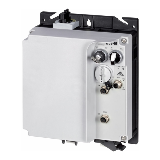
Page 123: Ramo5 Motor Starter
LED display for AS-Interface communication error i Sensor input I1 (M12 socket) with LED j Actuator output Q1 (M12 connector) with LED display - only in the version RAMO5-xx1… k Sensor input I2 (M12 socket) with LED l Motor feeder plug m Power plug (supply voltage 3 AC 400 V, N, PE) Rapid Link 5 ·... -
Page 124: Features
RAMO5 (Rapid Link Motor Control Unit) is an electronic motor starter for the direct start of three-phase motors up to 6.6 A (≥ 3 kW at 400 V). RAMO5 switches with thyristors and relays in the energy branch. This makes it possi- ble for the units to have a lifespan of more than 10 million switching cycles. -
Page 125: Connections
Power plug: Power supply (3 AC 400 V, N, PE) through a power adaptor cable (→ section 3.5, “Power plug”, page 90) b Data bus for controlling RAMO5 in automatic mode c Motor connection: Motor connection according DESINA specification d Sensor and fan connections Rapid Link 5 · RAMO5 · RASP5 10/19 MN034004EN www.eaton.com... -
Page 126: Special Technical Data
5 RAMO5 Motor starter 5.4 Special technical data 5.4 Special technical data The following tables show the technical data of the RAMO5 Motor Control Unit in the individual power classes with the allocated motor output. → The motor output allocation is based on the rated operational current. -
Page 127: Block Diagrams
5 RAMO5 Motor starter 5.5 Block diagrams 5.5 Block diagrams RAMO5-D Figure 85: Block diagram RAMO-D… a RAMO5-…-xxxRxx b RAMO5-xxx2… (230/277 V), RAMO-xxx4… (400/480 V) c RAMO5-xx1… Rapid Link 5 · RAMO5 · RASP5 10/19 MN034004EN www.eaton.com... - Page 128 5 RAMO5 Motor starter 5.5 Block diagrams RAMO5-W Figure 86: Block diagram RAMO-W… Rapid Link 5 · RAMO5 · RASP5 10/19 MN034004EN www.eaton.com...
-
Page 129: Led Displays
5 RAMO5 Motor starter 5.6 LED displays 5.6 LED displays The LEDs of motor control unit RAMO5 indicate the operating states and allow a quick diagnosis. State Description Clockwise rotating field of motor voltage (U-V-W) Not actuated OFF/RESET Green enabled (RUN mode) - Page 130 Flashing The detected fault (the fault signal's cause) has been fixed. (red) The fault signal can now be acknowledged with key switch OFF/RESET (→ The LED FLT goes out). Rapid Link 5 · RAMO5 · RASP5 10/19 MN034004EN www.eaton.com...
-
Page 131: Configure Special Settings
5.7 Configure special settings 5.7.1 Configure set rated motor current (P1-08) Before commissioning the RAMO5 motor control unit, the current monitor- ing function must be set to the rated motor current. To set parameter P1-08, the screw plug must be opened. -
Page 132: Sensor Inputs I1 And I2
0 = close – 1 = open Note: Change active only after POWER ON/OFF P3-07 DI2 Logic 0 = close – 1 = open Note: Change active only after POWER ON/OFF Rapid Link 5 · RAMO5 · RASP5 10/19 MN034004EN www.eaton.com... -
Page 133: Quick Stop And Interlocked Manual Operation
REV for edge or level control REV: of FWD and reverse I2 for edge or level control REV: Key switch reset and I2 no longer active for edge or level control Rapid Link 5 · RAMO5 · RASP5 10/19 MN034004EN www.eaton.com... -
Page 134: Phase Change
5 RAMO5 Motor starter 5.7 Configure special settings 5.7.4 Phase change Parameter P6-08 changes the rotating field at the output of RAMO5-W… from FWD to REV. The control logic and the LED indication remain in the FWD function. → For RAMO5-W… the P6-08 parameter setting should be changed by competent users according to the instructions in the manual. -
Page 135: Monitoring The Current Lower Limit
P5-10 Function Description Quick stop ON Response to sensors Quick stop OFF No response to sensors None DQ3 signals will not be transmitted None DQ3 signals will not be transmitted Rapid Link 5 · RAMO5 · RASP5 10/19 MN034004EN www.eaton.com... - Page 136 5 RAMO5 Motor starter 5.7 Configure special settings Rapid Link 5 · RAMO5 · RASP5 10/19 MN034004EN www.eaton.com...
-
Page 137: Rasp5 Speed Controller
STO input, with LED display m Motor-outgoer plug n Power plug, (supply voltage 3 AC 400 V, N, PE) o Device fan, mounted at the factory on RASP5-8… (4 kW) Rapid Link 5 · RAMO5 · RASP5 10/19 MN034004EN www.eaton.com... -
Page 138: Features
277 V AC or 400 V / 480 V AC output. In addition versions of RASP5 with built-in braking resistance also allow dynamic braking. DANGER RASP5 is not intended to be opened by the user. Open only in voltage-free state! Rapid Link 5 · RAMO5 · RASP5 10/19 MN034004EN www.eaton.com... -
Page 139: Connections
Power supply (3 AC 400 V, N, PE) through a power adaptor cable (→ section 3.5, “Power plug”, page 90) b Data bus for controlling RASP5 in automatic mode c Motor connection according DESINA specification d Sensor and fan connections Rapid Link 5 · RAMO5 · RASP5 10/19 MN034004EN www.eaton.com... -
Page 140: Special Technical Data
(380 - 480 V ±0 %, 45 - 66 Hz ±0 %) Input current Braking Braking value ≦ 30 ≦ 30 ≦ 30 ≦ 30 Switch-on threshold for the braking tran- V DC sistor Rapid Link 5 · RAMO5 · RASP5 10/19 MN034004EN www.eaton.com... - Page 141 < 10 < 10 < 10 < 10 Minimum pulse duration I3/I4 Longest permissible length of motor cable Weight 3.4/3.7 3.4/3.7 3.4/3.7 3.4/3.8 1) without bus runtime, depending on PLC. Rapid Link 5 · RAMO5 · RASP5 10/19 MN034004EN www.eaton.com...
-
Page 142: Overload Capacity
For requirements for higher switching frequencies (> 16 kHz), the load (output current) and/or the ambient temperature must be reduced. The RASP-FAN-S1 makes it possible to run the unit at higher ambient temperatures. Rapid Link 5 · RAMO5 · RASP5 10/19 MN034004EN www.eaton.com... - Page 143 8 kHz (90 °C) 12 kHz (85 °C) 16 kHz (80 °C) 24 kHz (75 °C) 32 kHz (70 °C) ϑ [°C] Figure 93: f = 4 - 32 kHz for RASP5-8… Rapid Link 5 · RAMO5 · RASP5 10/19 MN034004EN www.eaton.com...
-
Page 144: Block Diagram
6 RASP5 Speed controller 6.5 Block diagram 6.5 Block diagram Rapid Link 5 · RAMO5 · RASP5 10/19 MN034004EN www.eaton.com... -
Page 145: Led Indicators
→ AS interface setting the address Green → fatal peripheral error; internal ASi error Red flashing Sensor input I1 • not connected • Not triggered (no input signal) Green SI1 triggered (input signal) Rapid Link 5 · RAMO5 · RASP5 10/19 MN034004EN www.eaton.com... - Page 146 The detected fault (the fault signal's cause) has been fixed. The fault signal can now be acknowledged with key switch “OFF/RESET”. No signal present (logic 0) Green Signal present (logic 1) Rapid Link 5 · RAMO5 · RASP5 10/19 MN034004EN www.eaton.com...
-
Page 147: Configure Special Settings
The screw plug must be opened to adjust the parame- ters. Figure 95: RJ45 interface The parameterization can be via: • App, • Keypad, • “drivesConnect” software. ATTENTION The RJ45 interface is not designed for Ethernet communication. Rapid Link 5 · RAMO5 · RASP5 10/19 MN034004EN www.eaton.com... -
Page 148: Motor Cable Monitoring
Change only after POWER ON/OFF active P3-09 DI4 Logic 0 = close – 1 = open Note: Change only after POWER ON/OFF active → Sensors I3 and I4 require a Y connector of type RA-XM12-Y. Rapid Link 5 · RAMO5 · RASP5 10/19 MN034004EN www.eaton.com... - Page 149 Counterclockwise. When I3/I4 is reached, RASP5… switches to creep speed FF1. When SI1/SI2 is reached, the drive switches off. Application example: Turntable Note: I3 and I4 require the RA-XM12-Y connector. Rapid Link 5 · RAMO5 · RASP5 10/19 MN034004EN www.eaton.com...
- Page 150 Signal to drive ① Signal from key and selector switch Figure 98: Interlocked manual operation with creep speed (example: sensor input I1 and clockwise motion) a 13.5 ms ± 5 ms Rapid Link 5 · RAMO5 · RASP5 10/19 MN034004EN www.eaton.com...
-
Page 151: Phase Change
24 V DC voltage drops out with the second ramp (P2-13). To do this, the 24 V DC voltage must be supplied via the AS-interface connection M12. Rapid Link 5 · RAMO5 · RASP5 10/19 MN034004EN www.eaton.com... - Page 152 6.7 Configure special settings +24 V DC 100 mA External Power Supply Figure 99: Example of a motor ratings plate → The second deceleration time can be set with parameter P2-13. Rapid Link 5 · RAMO5 · RASP5 10/19 MN034004EN www.eaton.com...
-
Page 153: Configuration
Rapid Link system and lead to different operating states. → For more information on programming via the app, please visit the Download Center. Enter “AP040189” in the Quick Search field and click on Search. Rapid Link 5 · RAMO5 · RASP5 10/19 MN034004EN www.eaton.com... -
Page 154: Parameterization With Pc And The Drivesconnect Software
7.2 Parameterization with PC and the drivesConnect software … ① DX-CBL-PC-3MO ② DX-SPL-RJ45-2SL1PL ③ DX-CBL-RJ45-... ② ② RJ45 OP-BUS ③ ③ DX-CBL-PC-3M0 Figure 101: Parameterization with PC The optional DX-CBL-PC-3M0 communication cable is required for PC connection. Rapid Link 5 · RAMO5 · RASP5 10/19 MN034004EN www.eaton.com... -
Page 155: Pc Tool
To access one of the four main components, simply click on it: • Parameter Editor • Drive control/monitor (not available with Rapid Link) • Function block editor (not available with Rapid Link) • Scope/Data Logger Rapid Link 5 · RAMO5 · RASP5 10/19 MN034004EN www.eaton.com... -
Page 156: Parameter Editor
Figure 103: drivesConnect start screen When you open the Parameter Editor component, the program will show the following user interface: Figure 104: User interface for the “Parameter Editor” component - for RAMO Rapid Link 5 · RAMO5 · RASP5 10/19 MN034004EN www.eaton.com... - Page 157 8 PC tool 8.2 Parameter Editor Figure 105: User interface for the “Parameter Editor” component - for RASP → For more information on drivesConnect software, refer to MN040003EN manual. Rapid Link 5 · RAMO5 · RASP5 10/19 MN034004EN www.eaton.com...
- Page 158 8 PC tool 8.2 Parameter Editor Rapid Link 5 · RAMO5 · RASP5 10/19 MN034004EN www.eaton.com...
-
Page 159: Control Unit
START + ▲ . Display: Select Language. The display language can be changed using the ▲ and ▼ arrow keys. The selected language setting can then be saved by pressing the OK button. Rapid Link 5 · RAMO5 · RASP5 10/19 MN034004EN www.eaton.com... -
Page 160: Elements Of The Dx-Key Led2 External Control Unit
• Changes the value being displayed: A, rpm, etc. (real-time informa- tion) START • Parameter selection STOP • Reset – Resetting after an error message • Increment numeric value or parameter number DOWN • Decrement numeric value or parameter number Rapid Link 5 · RAMO5 · RASP5 10/19 MN034004EN www.eaton.com... -
Page 161: Adjust Parameters
STOP buttons to jump to the first parameter in the next parameter group. ▼ Press the and STOP buttons to jump to the first parameter in the previous parameter group. Rapid Link 5 · RAMO5 · RASP5 10/19 MN034004EN www.eaton.com... -
Page 162: Resetting Parameters (Reset)
(P2-32). Press the OK button to confirm. -> Only the “basic parameters,” i. e., the parameters in the first param- eter group (P1-01 to P1-14), will be accessible now. Rapid Link 5 · RAMO5 · RASP5 10/19 MN034004EN www.eaton.com... - Page 163 9 Control Unit 9.2 Extended parameter set → For more information and technical data on the DX-KEY-LED2 and DX-KEY-OLED control units, please refer to instructional leaflet IL04012020Z. Rapid Link 5 · RAMO5 · RASP5 10/19 MN034004EN www.eaton.com...
- Page 164 9 Control Unit 9.2 Extended parameter set Rapid Link 5 · RAMO5 · RASP5 10/19 MN034004EN www.eaton.com...
-
Page 165: Parameter List
Level 2 (menu P0 to menu P7) can be accessed by entering a password in parameter P1 14. The default passwords are: • Access to level 2: 101 Users can change this password as required: • Password for level 2: With parameter P2-32 Rapid Link 5 · RAMO5 · RASP5 10/19 MN034004EN www.eaton.com... -
Page 166: Menu Structure
Time elapsed, in which the drive has operated with a hh:mm:ss high temperature at the PCBs (ambient temperature). Displays the time in hours and minutes above 80 °C. The value is used for various internal protective func- tions. Rapid Link 5 · RAMO5 · RASP5 10/19 MN034004EN www.eaton.com... - Page 167 DC bus Voltage Ripple Log Displays the most recent 8 samples of the ripple of the DC bus voltage prior to a drive trip condition occurring. The sample interval is 20 ms. Rapid Link 5 · RAMO5 · RASP5 10/19 MN034004EN www.eaton.com...
- Page 168 This ID can be set by the user when developing the program. P0-59 Value@Pointer Pointer on an internal parameter Displays the value selected with P5-09. P0-60 reserved – P0-61 reserved – Rapid Link 5 · RAMO5 · RASP5 10/19 MN034004EN www.eaton.com...
-
Page 169: Parameter Group 1 ("Basic")
The value to be put in is determined by the level to be accessed. Level 2 (Access to parameter groups 0 to 8): P1-14 = P2-32 (Default: 101) Rapid Link 5 · RAMO5 · RASP5 10/19 MN034004EN www.eaton.com... -
Page 170: Parameter Group 2 ("Extended Functions")
0: OFF. All parameters can be accessed and changed 1: ON. Parameter values can be displayed, but cannot be changed. If a remote keypad is connected, parameters cannot be accessed. Rapid Link 5 · RAMO5 · RASP5 10/19 MN034004EN www.eaton.com... - Page 171 1: Function blocks enabled P2-36 Save Parameters @24V-ext. List of defined parameters – 1: If control voltage is present, the parameters will be saved. After that, the parameter is automatically set to 0. Rapid Link 5 · RAMO5 · RASP5 10/19 MN034004EN www.eaton.com...
-
Page 172: Parameter Group 3 ("Mechanical Brake And Digital Inputs")
0 = normally open 1 = normally closed Note: Change only after POWER ON/OFF active P3-11 t-dec Select B0 Selection deceleration ramp bit 0 External stop function 0: deactivated 1: activated Rapid Link 5 · RAMO5 · RASP5 10/19 MN034004EN www.eaton.com... -
Page 173: Parameter Group 5 ("Communication")
0: reserved 1: User defined ramp times with 2 decimal places 2: User register 3. Configuration with Function Block Editor. 3: User register 4. Configuration with Function Block Editor. Rapid Link 5 · RAMO5 · RASP5 10/19 MN034004EN www.eaton.com... - Page 174 P5-06). P5-09 is monstly used in conjunction with the Function Block Editor. P5-10 Disable QuickStop 0: Quick stop via sensors deactivated – 1: Quick stop via sensors activated; DQ3 signal active Rapid Link 5 · RAMO5 · RASP5 10/19 MN034004EN www.eaton.com...
-
Page 175: Parameter Group 6 ("Extended Motor Control")
Stop in FWD mode for edge or Stop in REV mode for edge or Stop in FWD mode for edge or Stop in REV mode for edge or signal control signal control signal control signal control Rapid Link 5 · RAMO5 · RASP5 10/19 MN034004EN www.eaton.com... -
Page 176: Parameter Groups For Rasp
Time elapsed, in which the drive has operated with a high heat- hh:mm:ss sink temperature Displays the time in hours and minutes above 85 °C. The value is used for various internal protective functions. Rapid Link 5 · RAMO5 · RASP5 10/19 MN034004EN www.eaton.com... - Page 177 DC-Link Log DC link voltage log Displays the most recent 8 samples of the DC bus voltage prior to a drive trip condition occurring. The sample interval is 256 ms. Rapid Link 5 · RAMO5 · RASP5 10/19 MN034004EN www.eaton.com...
- Page 178 1st value = Ud (“d” at the begin- ning of the line) Pressing the UP key on the drive keypad the display will change to Uq (“q” at the beginning of the line). Rapid Link 5 · RAMO5 · RASP5 10/19 MN034004EN www.eaton.com...
- Page 179 Speed reference received via fieldbus interface P0-64 Actual Switching Frequency Actual switching frequency. – The value may be less than the one set with P2-22. See also P2-23 P0-65 System Software Version System Software Version Rapid Link 5 · RAMO5 · RASP5 10/19 MN034004EN www.eaton.com...
-
Page 180: Parameter Group 1 ("Basic")
Current”, the decimal points on the display will flash to indicate an overload condition. If this condition persists, the drive will eventually trip, displaying I. t -trP, preventing thermal overload of the motor. Rapid Link 5 · RAMO5 · RASP5 10/19 MN034004EN www.eaton.com... - Page 181 The value to be put in is determined by the level to be accessed. Level 2 (Access to parameter groups 0 to 8): P1-14 = P2-32 (Default: 101) Rapid Link 5 · RAMO5 · RASP5 10/19 MN034004EN www.eaton.com...
-
Page 182: Parameter Group 2 ("Extended Functions")
”Motor Nom Speed” (P1-10) > 0, displayed in rpm. Frequency/Speed > P2-12 = t-acc2 Frequency/Speed < P2-12 = t-acc1 P2-13 t-dec2 Sets the deceleration ramp time 2 in seconds. 3000 Activation via pin 4 at AS-i. Rapid Link 5 · RAMO5 · RASP5 10/19 MN034004EN www.eaton.com... - Page 183 In this case P2-22 has to be set to twice the switching frequency mentioned on the filter. Example: Sine wave filter for 4 kHz --> Setting of P2-22: 8 kHz! Rapid Link 5 · RAMO5 · RASP5 10/19 MN034004EN www.eaton.com...
- Page 184 0: OFF. All parameters can be accessed and changed 1: ON. Parameter values can be displayed, but cannot be changed. If a remote keypad is connected, parameters cannot be accessed (except P1-14 and P2-33). Rapid Link 5 · RAMO5 · RASP5 10/19 MN034004EN www.eaton.com...
- Page 185 – The drive starts from the detected motor speed. A short start delay is possible if the rotor is stationary. Possible values: 0: Spin Start Off 1: Spin Start On Rapid Link 5 · RAMO5 · RASP5 10/19 MN034004EN www.eaton.com...
-
Page 186: Parameter Group 3 ("Mechanical Brake And Digital Inputs")
0 = normally open – 1 = normally closed Note: Change only after POWER ON/OFF active P3-11 t-dec Select B0 Selection deceleration ramp bit 0 – External stop function 0: deactivated 1: activated Rapid Link 5 · RAMO5 · RASP5 10/19 MN034004EN www.eaton.com... -
Page 187: Parameter Group 4 ("Brake Chopper And Dc Brake")
At very low temperatures (< -10 °C) the drive doesn’t work and indicates “Under temperature” (Fault code 09 “U-t”). Devices with internal brake resistor can use this to heat up the device. Parameter P4-08 determines the load cycle. Rapid Link 5 · RAMO5 · RASP5 10/19 MN034004EN www.eaton.com... -
Page 188: Parameter Group 5 ("Communication")
0: reserved 1: User defined ramp times with 2 decimal places 2: User register 3. Configuration with Function Block Editor. 3: User register 4. Configuration with Function Block Editor. Rapid Link 5 · RAMO5 · RASP5 10/19 MN034004EN www.eaton.com... - Page 189 P5-06). P5-09 is monstly used in conjunction with the Function Block Editor. P5-10 Disable QuickStop 0: Quick stop via sensors deactivated – 1: Quick stop via sensors activated; DQ3 signal active Rapid Link 5 · RAMO5 · RASP5 10/19 MN034004EN www.eaton.com...
-
Page 190: Parameter Group 6 ("Extended Motor Control")
The output torque is reduced to avoid overload. P6-11 EnhancedGeneratorControl EnhancedGeneratorControl Adaptation of the motor model in vector mode and with PM motors to achieve a better performance of the drive when regenerating. 0: disable 1: enable Rapid Link 5 · RAMO5 · RASP5 10/19 MN034004EN www.eaton.com... - Page 191 This can reduce thermal losses in the motor and drive, but will result in a less sinu- soidal motor current waveform. Rapid Link 5 · RAMO5 · RASP5 10/19 MN034004EN www.eaton.com...
-
Page 192: Parameter Group 7 ("Motor")
For PM-Motors: phase d-axis inductance value [Lsd] in Henry [H] P7-06 Motor Stator Inductance q-Axis Stator inductance of the motor, magnetizing 6553.5 For PM-Motors: phase d-axis inductance value [Lsd] in Henry [H] Rapid Link 5 · RAMO5 · RASP5 10/19 MN034004EN www.eaton.com... -
Page 193: Parameter P1-13
Stop in REV mode with edge FWD operation with fixed REV operation with fixed signal control control frequency 1 (FF1) for edge or frequency 1 (FF1) for edge or signal control signal control Rapid Link 5 · RAMO5 · RASP5 10/19 MN034004EN www.eaton.com... - Page 194 10 Parameter list 10.4 Parameter groups for RASP Rapid Link 5 · RAMO5 · RASP5 10/19 MN034004EN www.eaton.com...
-
Page 195: Communications
FF1 to FF3 (digital setpoint value memory) are called up in binary code. If DQ2 and DQ3 are not activated, frequency value f set at spindle potentiometer n is output (analog setpoint memory, 0 to 50 Hz). Rapid Link 5 · RAMO5 · RASP5 10/19 MN034004EN www.eaton.com... -
Page 196: Data Cable
(assigned an address on) a single AS-i line. The response time when a command is sent via an AS-Interface is 160 μ s per card; for 31 cards this is 5 ms. Rapid Link 5 · RAMO5 · RASP5 10/19 MN034004EN www.eaton.com... -
Page 197: Gateway
(on AS-i version 2.1 and higher). The slaves’ addresses do not have to be consecutive. → For information on how to assign addresses for and configure the AS-Interface, please consult the manual for the gateway you are using. Rapid Link 5 · RAMO5 · RASP5 10/19 MN034004EN www.eaton.com... -
Page 198: Replacing Rapid Link Devices In The As-I Circuit
Figure 109: Junction M12 (order no.: ZB2-100-AZ1) The Rapid Link function modules have an AS-Interface M12 plug-in connec- tor that fits the M12 junction. Function AS-Interface+ AS-Interface - +24 V DC – Rapid Link 5 · RAMO5 · RASP5 10/19 MN034004EN www.eaton.com... -
Page 199: External Quick Stop
11.3.1 Extension circuit For connecting the M12 junction ZB2-100-A21 with Rapid Link modules RAMO5 or RASP5, extension cable RA-XM12-1M can be used. This 1 m long connection cable is prefabricated with an M12 socket (connection to RAMO or RASP) and an M12 plug (M12 junction). -
Page 200: Cable Routing
100 mm (f 3.94“) Figure 113: Laying of signal and power cables a Power cable: Mains connection (power bus, adaptor cable), motor cable b Control cables: As-Interface (data bus), sensor/actuator connection Rapid Link 5 · RAMO5 · RASP5 10/19 MN034004EN www.eaton.com... -
Page 201: Rasp Actuation
Through outputs DQ2 and DQ3 fixed frequencies FF1 to FF3 (digital setpoint value memory) are called up in binary code. • If DQ2 and DQ3 are not activated, the frequency set in FF0 is output. Rapid Link 5 · RAMO5 · RASP5 10/19 MN034004EN www.eaton.com... -
Page 202: Asi Control Ramo
The START signal or enable for the requested operating direction is issued through DQ0 (FWD) or DQ1 (REV). • DQ2 can be used to switch output O3 to HIGH or LOW. Rapid Link 5 · RAMO5 · RASP5 10/19 MN034004EN www.eaton.com... -
Page 203: Diagnostics And Troubleshooting Via As-Interface
Hold the switch in this position for at least one second so that the RAMO5 unit will detect the command. The Reset signal via AS-i provides an additional reset option for RAMO5 units in case the latter cannot be locally reset due to accessibility issues. -
Page 204: Op-Bus
Figure 114: System configuration for system bus 11.5.1 Hardware The devices of the RAMO5 and RASP5 series have an 8-pin RJ45 socket on the front. This socket is used for the devices to communicate. Depending on the series of devices, ports are available for the various bus protocols. One of... - Page 205 OP system bus, they must have different addresses. The address is set using parameter P5-01: Addressing has to be done before the connection to the OP system bus. This can be done using the DX-KEY-OLED operator panel. Rapid Link 5 · RAMO5 · RASP5 10/19 MN034004EN www.eaton.com...
- Page 206 → The previous address of the device is displayed. Use the ▲ or ▼ button to select the desired (new) address. ▶ ▶ Press the STOP and ▼ buttons simultaneously. → Communication is restored. Rapid Link 5 · RAMO5 · RASP5 10/19 MN034004EN www.eaton.com...
- Page 207 In the delivery condition, this is always “1”. If the address of the device has already been reconfigured, the current value can be read in the drivesConnect parameter software and in the RAMO5 and RASP5 series devices on the control unit in the device.
- Page 208 11 Communications 11.5 OP-Bus Rapid Link 5 · RAMO5 · RASP5 10/19 MN034004EN www.eaton.com...
-
Page 209: Error Messages
The auto reset function can be set using parameters P2-24 and P2-26. The P2-26 parameter determines the time which will elapse between consecutive drive reset attempts when Auto Reset is enabled by P2-24. Rapid Link 5 · RAMO5 · RASP5 10/19 MN034004EN www.eaton.com... -
Page 210: Error List
• Change the parameter values (again) and save them once more. • If the message appears again, please contact your nearest Eaton sales branch. Error in internal memory. The parameters have not been saved and the default dAtA-E settings have been loaded. - Page 211 • Increase the value of P5-02 to an acceptable value. No internal connection to an optional card OF-01 Optional module in undefined operating state OF-02 Sensor fault - overload or short circuit OF-10 Rapid Link 5 · RAMO5 · RASP5 10/19 MN034004EN www.eaton.com...
-
Page 212: Rasp Error List
In this case, use P1-03 to make the acceleration ramp longer or reduce the load. • Make sure that the motor is not being mechanically blocked and that there are no additional loads on the motor. Rapid Link 5 · RAMO5 · RASP5 10/19 MN034004EN www.eaton.com... - Page 213 • Check to make sure that all the mains supply phases are present and that their voltage balance falls within the permissible tolerance range (3 %. • Reduce the load if possible. • If the fault persists, please contact your nearest Eaton sales branch. Rapid Link 5 · RAMO5 · RASP5 10/19 MN034004EN www.eaton.com...
- Page 214 • Change the parameter values (again) and save them once more. • If the message appears again, please contact your nearest Eaton sales branch. Error in internal memory. The parameters have not been saved and the default dAtA-E settings have been loaded.
- Page 215 • Increase the value of P5-02 to an acceptable value. No internal connection to an optional card OF-01 Optional module in undefined operating state OF-02 Sensor fault - overload or short circuit OF-10 Rapid Link 5 · RAMO5 · RASP5 10/19 MN034004EN www.eaton.com...
- Page 216 12 Error messages 12.3 RASP Error list Rapid Link 5 · RAMO5 · RASP5 10/19 MN034004EN www.eaton.com...
-
Page 217: Index
......25 Rapid Link 5 · RAMO5 · RASP5 10/19 MN034004EN www.eaton.com... - Page 218 ....40 Rated operational data ....15, 19 Rapid Link 5 · RAMO5 · RASP5 10/19 MN034004EN www.eaton.com...
Need help?
Do you have a question about the RAMO5 and is the answer not in the manual?
Questions and answers