MacDon R1 Series Operator's Manual
Rotary disc pull-type
Hide thumbs
Also See for R1 Series:
- Operator's manual (346 pages) ,
- Installation instructions manual (48 pages) ,
- Quick start manual (2 pages)

Related Manuals for MacDon R1 Series


Summary of Contents for MacDon R1 Series
- Page 1 R1 Series Rotary Disc Pull-Type Operator s Manual 262634 Revision A Original Instruction The Harvesting Specialists.
- Page 2 © 2024 MacDon Industries, Ltd. The information in this publication is based on the information available and in effect at the time of printing. MacDon Industries, Ltd. makes no representation or warranty of any kind, whether expressed or implied, with respect to the...
- Page 3 Declaration of Conformity 262634 Revision A...
- Page 4 262634 Revision A...
- Page 5 262634 Revision A...
- Page 6 Introduction This manual contains safety, operating, and maintenance procedures for the MacDon R113 4.0 m (13 ft.) and R116 4.9 m (16 ft.) Rotary Disc Pull-Types. Your machine The rotary disc pull-type is designed to cut, condition, and lay a wide variety of grasses and hay crops in windrows.
- Page 7 Store the operator s manual and the parts catalog in plastic manual case (A) at the right side of the rotary disc pull-type. NOTE: Keep your MacDon publications up-to-date. The most current version can be downloaded from our website www.
-
Page 8: Summary Of Changes
Summary of Changes At MacDon, we re continuously making improvements: occasionally these improvements affect product documentation. The following list provides an account of major changes from the previous version of this document. Internal Use Summary of Change Section Only Declaration of Conformity, page i Updated for new model year. -
Page 9: Serial Numbers
Serial Numbers Record the serial numbers of the pull-type, the hitch, and the transport option (if equipped) provided below. Rotary disc pull-type serial number (A): Model year: Rotary Disc Pull-Type Serial Number Location Hitch serial number (A): Hitch Serial Number Location (A) – R113 Shown, R116 Similar Optional transport system serial number (A):... -
Page 11: Table Of Contents
TABLE OF CONTENTS Declaration of Conformity ..........................i Introduction .............................. iv Summary of Changes........................... vi Serial Numbers............................vii Chapter 1: Safety ............................1 1.1 Safety Alert Symbols ..........................1 1.2 Signal Words ............................2 1.3 General Safety ............................3 1.4 Operational Safety..........................5 1.5 Owner/Operator Responsibilities ......................6 1.6 Maintenance Safety ..........................7 1.7 Hydraulic Safety .............................9 1.8 Tire Safety............................ - Page 12 TABLE OF CONTENTS 3.7 Attaching Rotary Disc Pull-Type to Tractor ....................49 3.7.1 Attaching with Drawbar Hitch ......................49 3.7.2 Attaching with Two-Point Hitch ...................... 51 3.7.3 Connecting Hydraulics ........................54 3.7.4 Connecting Electrical Wiring Harness....................56 3.8 Detaching Rotary Disc Pull-Type from Tractor .................... 59 3.8.1 Detaching from Drawbar .......................
- Page 13 TABLE OF CONTENTS Installing Tall Crop Divider......................104 Removing Tall Crop Divider......................104 3.16 Conditioning Roll Type ........................106 3.16.1 Conditioner Roll Gap......................... 106 Checking Roll Gap ........................106 Adjusting Roll Gap Polyurethane Rolls..................107 Adjusting Roll Gap Steel Rolls ....................108 3.16.2 Roll Tension ..........................
- Page 14 TABLE OF CONTENTS 4.4 Cutterbar System..........................150 4.4.1 Cutterbar Doors......................... 150 Inspecting Cutterbar Doors......................150 4.4.2 Maintaining Curtains ........................151 Inspecting Curtains ........................151 Removing Cutterbar Door Curtains ....................152 Installing Cutterbar Door Curtains....................153 Removing Cutterbar Inboard Curtain.................... 154 Installing Cutterbar Inboard Curtain .....................
- Page 15 TABLE OF CONTENTS Removing Large Driven Drums and Driveline ................. 220 Installing Large Driven Drums and Driveline................... 223 Removing Large Non-Driven Drums ..................... 227 Installing Large Non-Driven Drums....................228 4.4.13 Replacing Cutterbar Spindle Shear Pin..................230 Removing Cutterbar Spindle Shear Pin..................231 Installing Cutterbar Spindle Shear Pin ...................
- Page 16 TABLE OF CONTENTS 4.6 Hydraulics ............................291 4.6.1 Checking Hydraulic Hoses and Lines ....................291 4.6.2 Hydraulic Cylinders........................291 4.7 Electrical System ..........................292 4.7.1 Maintaining Electrical System....................... 292 4.7.2 Servicing Amber Hazard/Signal Lights .................... 292 Replacing Amber Hazard/Signal Bulb.................... 292 Replacing Amber Hazard/Signal Light Fixture .................
- Page 17 TABLE OF CONTENTS 7.1.2 Metric Bolt Specifications Cast Aluminum ..................333 7.1.3 Flare-Type Hydraulic Fittings ......................334 7.1.4 O-Ring Boss Hydraulic Fittings Adjustable ..................335 7.1.5 O-Ring Boss Hydraulic Fittings Non-Adjustable................336 7.1.6 O-Ring Face Seal Hydraulic Fittings....................337 7.1.7 Tapered Pipe Thread Fittings......................338 7.2 Conversion Chart..........................
-
Page 19: Chapter 1: Safety
Chapter 1: Safety Understanding and consistently following these safety procedures will help to ensure the safety of those operating the machine and of bystanders. 1.1 Safety Alert Symbols The safety alert symbol indicates important safety messages in this manual and on safety signs on the machine. This symbol means: ATTENTION! BECOME ALERT! -
Page 20: Signal Words
SAFETY 1.2 Signal Words Three signal words, DANGER, WARNING, and CAUTION, are used to alert you to hazardous situations. Two signal words, IMPORTANT and NOTE, identify non-safety related information. Signal words are selected using the following guidelines: DANGER Indicates an imminently hazardous situation that, if it is not prevented, will result in death or serious injury. WARNING Indicates a potentially hazardous situation that, if it is not prevented, could result in death or serious injury. -
Page 21: General Safety
SAFETY 1.3 General Safety Operating, servicing, and assembling machinery presents several safety risks. These risks can be reduced or eliminated by following the relevant safety procedures and wearing the appropriate personal protective equipment. CAUTION The following general farm safety precautions should be part of your operating procedure for all types of machinery. - Page 22 SAFETY Wear close-fitting clothing and cover long hair. NEVER wear dangling items such as hoodies, scarves, or bracelets. Keep all shields in place. NEVER alter or remove safety equipment. Ensure that the driveline guards can rotate independently of their shaft, and that they can telescope freely.
-
Page 23: Operational Safety
SAFETY 1.4 Operational Safety Follow all the safety and operational instructions given in this manual. CAUTION • Follow all safety and operational instructions provided in your operator's manuals. • Never attempt to start the engine or operate the machine except from the seat. •... -
Page 24: Owner/Operator Responsibilities
SAFETY 1.5 Owner/Operator Responsibilities Owning and operating heavy equipment comes with certain duties. CAUTION • It is your responsibility to read and understand this manual completely before operating the pull-type. Contact your Dealer if an instruction is not clear to you. •... -
Page 25: Maintenance Safety
SAFETY 1.6 Maintenance Safety Maintaining your equipment safely requires that you follow the relevant safety procedures and wear the appropriate personal protective equipment for the task. To ensure your safety while maintaining the machine: Review the operator s manual and all safety items before operating or performing maintenance on the machine. - Page 26 SAFETY Wear protective gear when working on the machine. Wear heavy gloves when working on knife components. Figure 1.11: Personal Protective Equipment 262634 Revision A...
-
Page 27: Hydraulic Safety
SAFETY 1.7 Hydraulic Safety Because hydraulic fluid is under extreme pressure, hydraulic fluid leaks can be very dangerous. Follow the proper safety procedures when inspecting hydraulic fluid leaks and servicing hydraulic equipment. Always place all hydraulic controls in NEUTRAL before leaving the operator s seat. -
Page 28: Tire Safety
SAFETY 1.8 Tire Safety Inflating, installing, removing, and handling tires presents several safety risks that must be taken into account. WARNING • A tire can explode during inflation, causing serious injury or death. • Follow the proper procedures when mounting a tire. Failure to do so can produce an explosion, causing serious injury or death. -
Page 29: Decommissioning And Disposing Of Agricultural Equipment
SAFETY 1.9 Decommissioning and Disposing of Agricultural Equipment When agricultural equipment is no longer serviceable and needs to be decommissioned and disposed of, recyclable materials including ferrous and non-ferrous metals, rubber, and plastics; fluids such as lubricants, refrigerants, and fuels; and hazardous materials found in batteries, some light bulbs, and electronic equipment must be handled safely and not introduced into the environment. - Page 30 SAFETY Use appropriate personal protective equipment when removing and handling objects and materials. Use appropriate personal protective equipment when handling objects with residue from pesticides, fertilizers, or other agricultural chemicals. Follow local regulations when handling and disposing of these objects. Safely release stored energy from suspension components, springs, hydraulic, and electrical systems.
-
Page 31: Safety Signs
SAFETY 1.10 Safety Signs Safety signs are decals placed on the machine where there is a risk of personal injury, or where the Operator should take extra precautions before operating the controls. They are usually yellow. Keep safety signs clean and legible at all times. Replace safety signs that are missing or illegible. -
Page 32: Safety Sign Decal Locations
SAFETY 1.11 Safety Sign Decal Locations Replace missing or damaged decals. Figure 1.20: Safety Sign Decal Locations – Top View, R113 PT A - 194466 B - 247167 C - 194465 D - 184372 E - 190546 F - 113482 G - 166466 Figure 1.21: Safety Sign Decals 262634... - Page 33 SAFETY Figure 1.22: Safety Sign Decal Locations – Top View, R116 PT A - 194466 B - 247167 C - 194465 D - 184372 E - 190546 F - 113482 G - 166466 Figure 1.23: Safety Sign Decals 262634 Revision A...
- Page 34 SAFETY Figure 1.24: Safety Sign Decal Locations – Left Side A - 113482 B - 174436 C - 259058 D - 247166 E - 171287 Figure 1.25: Safety Sign Decal Locations – Right Side A - 171287 B - 259058 262634 Revision A...
- Page 35 SAFETY Figure 1.26: Safety Sign Decal Locations – Roll Conditioner A - 190546 B - 184385 C - 184371 D - 246959 E - 246956 F - NO STEP Symbol (Imprinted on Shield) 262634 Revision A...
- Page 36 SAFETY Figure 1.27: Safety Sign Decal Locations – Finger Conditioner A - 184385 B - 184371 C - 184422 D - 190546 E - NO STEP Symbol (Imprinted on Shield) 262634 Revision A...
- Page 37 SAFETY Figure 1.28: Safety Sign Decal Locations – Hitch, R116 PT Shown, R113 PT Similar A - 194464 B - 113482 C - 174436 D - 259058 Figure 1.29: Safety Sign Decal Locations – Transport A - 184386 B - 246959 262634 Revision A...
-
Page 38: Understanding Safety Signs
SAFETY 1.12 Understanding Safety Signs Safety sign decals use illustrations to convey important safety or equipment maintenance information. 113482 General hazard pertaining to machine operation and servicing DANGER To prevent injury or death from improper or unsafe machine operation: Read the operator s manual and follow all safety instructions. - Page 39 SAFETY 171287 Rotary disc pull-type crushing hazard DANGER To prevent injury or death from the fall of a raised pull-type: Fully raise the pull-type, stop the engine, remove the key, and engage the hydraulic safety lock before going under the pull-type.
- Page 40 SAFETY 184372 General hazard regarding machine operation and servicing DANGER To prevent injury or death from the improper or unsafe operation of the machine: Read the operator s manual and follow all safety instructions. If you do not have a manual, obtain one from your Dealer.
- Page 41 SAFETY 184386 Pinch point hazard CAUTION To prevent injury: Do NOT reach into pinch area. Figure 1.37: 184386 184422 Hand and arm entanglement hazard WARNING To prevent injury: Stop the engine and remove the key before opening any shielding. Do NOT operate the header without the shields in place. Figure 1.38: 184422 190546 Slipping hazard...
- Page 42 SAFETY 194464 General hazard DANGER To prevent injury or death: Stop engine and remove key before service. Read tractor and pull-type manufacturer s manuals for inspection and maintenance instructions. Figure 1.40: 194464 194465 Blade cutting hazard WARNING To prevent injury from sharp cutting blades: Do NOT operate without shields in place.
- Page 43 SAFETY 246956 Driveline entanglement hazard DANGER To prevent injury: Shut down the engine and remove the key from the ignition before opening the shield. Do NOT operate the machine without the shields in place. Figure 1.43: 246956 246959 Pinch point hazard CAUTION To prevent injury: Do NOT reach into the pinch area.
- Page 44 SAFETY 247167 Blade cutting hazard WARNING To prevent injury from sharp cutting blades: Do NOT operate without shields in place. Disengage power take-off, stop engine and remove key before opening covers. Blades may continue to rotate after power is shut off. Listen and look for evidence of rotation before opening shield.
-
Page 45: Chapter 2: Product Overview
Chapter 2: Product Overview Refer to this section to learn about the machine s dimensions, weights, and specifications. 2.1 Definitions The following terms, abbreviations, and acronyms are used in this manual. Table 2.1 Definitions Term Definition American Petroleum Institute Articulated Power Turn A headed and externally threaded fastener designed to be paired with a nut Bolt A hydraulic cylinder or manually adjustable turnbuckle type connection between the... - Page 46 PRODUCT OVERVIEW Table 2.1 Definitions (continued) Term Definition An axial load placed on a bolt or screw, usually measured in Newtons (N) or pounds (lb.). Tension This term can also be used to describe the force a belt exerts on a pulley or sprocket Turns from finger tight TFFT The product of a force * the length of a lever arm, usually measured in Newton-meters...
-
Page 47: Component Identification
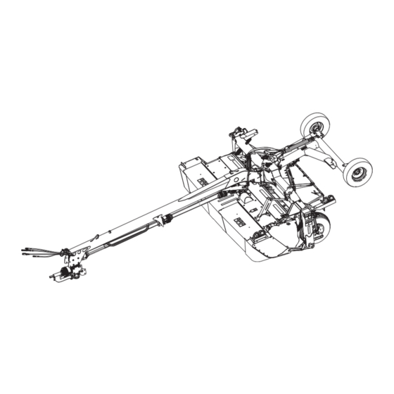
PRODUCT OVERVIEW 2.2 Component Identification Being able to identify the parts and systems of your rotary disc pull-type will make looking up content in its reference manuals much easier. Figure 2.1: Rotary Disc Pull-Type with Finger Conditioner A - Cutterbar Door B - Header Swivel Gearbox C - Center-Link D - Amber Hazard/Turn Signal Light (x2) - Page 48 PRODUCT OVERVIEW Figure 2.3: Rotary Disc Pull-Type with Finger Conditioner A - Optional Transport B - Forming Shield Cover C - Transport Locking Cylinder D - Skid Shoe E - Side Deflector F - Rear Curtain Figure 2.4: Hitch and Driveline — R116 Shown, R113 Similar A - Control Hoses B - Primary Driveline C - Hose Support...
- Page 49 PRODUCT OVERVIEW Figure 2.5: Hitch Options A - Tractor Two-Point Hitch Adapter B - Tractor Drawbar Hitch Adapter C - Tractor Utility Hitch Adapter 262634 Revision A...
-
Page 50: Product Specifications
PRODUCT OVERVIEW 2.3 Product Specifications Consult this section to learn about dimensions, weight, and equipment specifications. NOTE: Specifications and design are subject to change without notice or obligation to revise previously sold units. Table 2.2 Rotary Disc Pull-Type Specifications Components R113 R116 Frame and Structure... - Page 51 PRODUCT OVERVIEW Table 2.2 Rotary Disc Pull-Type Specifications (continued) Components R113 R116 4HB belt driven enclosed timing gearbox and driveline Drive Conditioner system Intermeshing rolls (steel or polyurethane) Conditioner speed 900 rpm Length of rolls 3275 mm (10 ft. 9 in.) Steel on steel 229 mm (9 in.) / 179 mm (7 in.) O.D.
-
Page 53: Chapter 3: Operation
Chapter 3: Operation Safely operating your machine requires familiarizing yourself with its capabilities. 3.1 Lift Cylinder Lock-Out Valves To prevent unintentional raising or lowering of the rotary disc pull-type, engage the lift cylinder lock-out valves before servicing, repairing, or unplugging your machine. The lift cylinder lock-out valves are located on the lift cylinders at the back of the rotary disc pull-type. -
Page 54: Disengaging Locks
OPERATION 3. Close lock-out valve (A) on each auxiliary lift cylinder by turning the handle to the closed position (90° angle to the hose). Figure 3.2: Lift Cylinder Lock-Out Valve in Closed Position 3.1.2 Disengaging Locks Engage the hydraulic lock-out valves when you are transporting or servicing the machine. DANGER To prevent bodily injury or death from the unexpected start-up of the machine, always stop the engine and remove the key from the ignition before making adjustments to the machine. - Page 55 OPERATION 3. Move cylinder control lever (A) forward to position (B) to lower the machine. Figure 3.4: Tractor Cylinder Control Lever 262634 Revision A...
-
Page 56: Driveshields
OPERATION 3.2 Driveshields Driveshields offer protection from the rotating belts and drives. The header has two driveshields: one on the left side, and one on the right side. 3.2.1 Opening Driveshields The driveshields offer protection from moving components. Open them only when you intend to service the header. DANGER To prevent bodily injury or death from the unexpected start-up of the machine, always stop the engine and remove the key from the ignition before making adjustments to the machine. -
Page 57: Closing Driveshields
OPERATION 3. Insert the flat end of tool (A) into latch (B) and turn it counterclockwise to unlock the driveshield. Figure 3.7: Driveshield Latch 4. Pull the top of driveshield (A) away from the header to open it. NOTE: For improved access, lift the driveshield off the pins at the base of the shield, and lay the shield on the header. - Page 58 OPERATION 1. Position the driveshield onto the pins, if necessary. 2. Push driveshield (A) to engage latch (B). 3. Ensure that the driveshield is properly secured. Figure 3.9: Driveshield and Latch 4. Replace tool (B) and lynch pin (A) onto pin (C). Figure 3.10: Left Driveshield 262634 Revision A...
-
Page 59: Cutterbar Doors
OPERATION 3.3 Cutterbar Doors Two doors with rubber curtains provide access to the cutterbar area. WARNING To reduce the risk of personal injury and machine damage, do NOT operate the machine without all the cutterbar doors down or without curtains installed and in good condition. Objects in the path of the blades can eject with considerable force when the machine is started. -
Page 60: Opening Cutterbar Doors Export
OPERATION 3. Lift up doors (A) at the front of the machine. Figure 3.12: Cutterbar Doors and Curtains 3.3.2 Opening Cutterbar Doors – Export Machines sold outside North America have a tool-operated latch on the cutterbar doors. DANGER To prevent bodily injury or death from the unexpected startup of the machine, always stop the engine and remove the key from the ignition before leaving the operator’s seat. -
Page 61: Closing Cutterbar Doors
OPERATION 4. Use a rod or screwdriver to press down on latch (A) to release the cutterbar door. Figure 3.14: Cutterbar Door Latch – Cutaway View 5. Lift up on doors (A) while pressing down on the latch. Figure 3.15: Cutterbar Doors and Curtains 3.3.3 Closing Cutterbar Doors Do NOT operate the machine without closing the cutterbar doors. - Page 62 OPERATION 1. Pull down on door (A) from the top to close. 2. Ensure that the curtains hang properly and completely enclose the cutterbar area. Figure 3.16: Cutterbar Doors and Curtains 262634 Revision A...
-
Page 63: Daily Start-Up Check
OPERATION 3.4 Daily Start-Up Check Perform this procedure before operating the machine. CAUTION • Ensure that the tractor and the rotary disc pull-type are properly attached, that all controls are in neutral, and that the tractor brakes are engaged. • Clear the area of bystanders. Walk around the rotary disc pull-type to confirm that no one is nearby. •... -
Page 64: Preparing Tractor For Rotary Disc Pull-Type
OPERATION 3.5 Preparing Tractor for Rotary Disc Pull-Type To attach the rotary disc pull-type to a tractor, the tractor must meet the power and hydraulic requirements. 3.5.1 Tractor Requirements The tractor used to pull the rotary disc pull-type must meet the requirements outlined in the table. Table 3.1 Tractor Requirements Minimum Drawbar Minimum Hydraulics... - Page 65 OPERATION Table 3.2 SAE Standard A482 Specifications 1000 rpm Power Take-Off (PTO) 1 3/8 in. Diameter 1 3/4 in. Diameter Dimension 406 mm (16 in.) 508 mm (20 in.) 200 350 mm (7 7/8 13 3/4 in.) 203 mm (8 in.) recommended 330 432 mm (13 17 in.) 406 mm (16 in.) recommended 262634...
-
Page 66: Setting Up Rotary Disc Pull-Type Hitch
OPERATION 3.6 Setting up Rotary Disc Pull-Type Hitch MacDon R1 Series Rotary Disc Pull-Types are factory-fitted with either a drawbar or a two-point hitch. Your Dealer will have installed the proper hitch adapter for your tractor. 3.6.1 Installing Drawbar Hitch Adapter The hitch adapter allows the drawbar to connect with the hitch casting. -
Page 67: Attaching Rotary Disc Pull-Type To Tractor
OPERATION 3.7 Attaching Rotary Disc Pull-Type to Tractor The rotary disc pull-type can be attached to the tractor with a drawbar hitch or a two-point hitch. Refer to the attachment procedure that applies to your tractor: 3.7.2 Attaching with Two-Point Hitch, page 51 3.7.1 Attaching with Drawbar Hitch, page 49 3.7.1 Attaching with Drawbar Hitch If the rotary disc pull-type was configured for a tractor with a drawbar hitch, and the tractor s hitch has been adjusted... - Page 68 OPERATION 3. Move the tractor to position drawbar hitch adapter (A) under pin (B) in the hitch. 4. Shut down the engine, and remove the key from the ignition. 5. Adjust the hitch height as necessary with the jack. Figure 3.21: Rotary Disc Pull-Type Hitch 6.
-
Page 69: Attaching With Two-Point Hitch
OPERATION 11. Raise jack (A), and remove pin (B). Figure 3.24: Hitch Jack 12. Move jack (A) to the storage position on top of the hitch, and secure it with pin (B). 13. Proceed to 3.7.3 Connecting Hydraulics, page Figure 3.25: Drawbar Jack Storage 3.7.2 Attaching with Two-Point Hitch If the rotary disc pull-type was configured for a tractor with a two-point hitch, then the rotary disc pull-type can now be attached to the tractor. - Page 70 OPERATION 1. Position the tractor and align hitch arms (A) with hitch adapter (B). 2. Shut down the engine, and remove the key from the ignition. 3. Remove lynch pins (C) and washers from the hitch adapter. Figure 3.26: Two-Point Hitch Configuration 4.
- Page 71 OPERATION 6. Check distance (C) between tractor primary power take-off (PTO) shaft (A) and rotary disc pull-type hitch gearbox shaft (B) without the front half of the driveline attached. 7. Ensure that distance (C) does NOT exceed the dimensions listed in Table 3.3, page Table 3.3 Distance between Hitch Gearbox and Tractor PTO Distance (C)
-
Page 72: Connecting Hydraulics
OPERATION 14. Rotate stand (A) upward and into the storage position. Figure 3.31: Repositioning Hitch Stand 15. Insert pin (A) and secure stand (B) in the storage position. Figure 3.32: Hitch Stand in Storage Position 3.7.3 Connecting Hydraulics Hydraulic hoses and lines distribute hydraulic fluid to the various components on the rotary disc pull-type. WARNING Do NOT use remote hydraulic system pressures over 20,684 kPa (3000 psi). - Page 73 OPERATION Table 3.4 Hydraulic System Hoses Tractor System Hose Identification Hydraulics Red #1 - pressure Lift (A) Blue #1 - return (only Control 1 with transport installed) Swing/ Red #2 - pressure Control 2 Transport (B) Blue #2 - return Red #3 - pressure Tilt (C) Control 3...
-
Page 74: Connecting Electrical Wiring Harness
OPERATION 3.7.4 Connecting Electrical Wiring Harness The electrical wiring harness allows the tractor to control the rotary disc pull-type s electrical components. 1. Ensure that pin #4 (A) in the tractor receptacle is NOT continuously energized (for instructions, refer to your tractor operator s manual). - Page 75 OPERATION If your tractor has a three-pin auxiliary power connection (A): 5. Connect two wires (B) from the three-pin auxiliary connector to power wires (C) on the control box, wrap the connections with electrical tape, and skip to Step 7, page Figure 3.37: Three-Pin Auxiliary Connector If your tractor does not have a three-pin auxiliary power connection: 6.
- Page 76 OPERATION NOTE: The transport control box has a 10 amp fuse (A) inside. If this fuse fails, the transport function will not activate. Figure 3.39: Control Box Interior 7. Place the control box inside the tractor cab. 262634 Revision A...
-
Page 77: Detaching Rotary Disc Pull-Type From Tractor
OPERATION 3.8 Detaching Rotary Disc Pull-Type from Tractor Detach the rotary disc pull-type from the tractor for servicing or storing. 3.8.1 Detaching from Drawbar Detach the rotary disc pull-type from the tractor for servicing or storing. DANGER • To prevent accidental movement of the tractor, shut off the engine, engage the parking brake, and remove the key from the ignition. - Page 78 OPERATION 7. Disconnect the hydraulic hoses and electrical harness from the tractor and store the hose ends and electrical connector in hose support (A) at front of hitch as shown. Figure 3.41: Hose Support 8. Pull pin (B) securing jack (A) at storage location and remove the jack.
- Page 79 OPERATION 11. Disconnect safety chain (B) from the drawbar and store it on the hitch. 12. Pull back collar (A) on the driveline, slide the coupler off the tractor power take-off shaft, and rest the driveline on the hook (not shown). Figure 3.44: Driveline and Jack 13.
-
Page 80: Detaching From Two-Point Hitch
OPERATION 3.8.2 Detaching from Two-Point Hitch Detach the rotary disc pull-type from the tractor for servicing or storing. DANGER • To prevent accidental movement of tractor, shut off the engine, engage the parking brake, and remove the key. • To maintain stability, always lower the machine completely. Block the rotary disc pull-type wheels before detaching from tractor. - Page 81 OPERATION 7. Disconnect the hydraulic hoses and the electrical harness. Store the hose ends and the electrical connector at the front of the hitch as shown. NOTE: Control box (A) is also stored at the front of the hitch. Figure 3.48: Front of Hitch 8.
- Page 82 OPERATION 10. Hold stand (A), and pull lock (B) to disengage the stand. Figure 3.51: Hitch Stand and Lock 11. Lower stand (A), rotate lock (C) counterclockwise to horizontal position, and push the lock to engage the stand. 12. Check that stand (A) is locked. 13.
-
Page 83: Breaking In Rotary Disc Pull-Type
OPERATION 3.9 Breaking in Rotary Disc Pull-Type After attaching the rotary disc pull-type to the tractor for the first time, operate the machine at low speed for 5 minutes while watching and listening FROM THE OPERATOR’S SEAT for binding or interfering parts. DANGER Before investigating an unusual sound or attempting to correct a problem, shut down the engine, engage the parking brake, and remove the key from the ignition. -
Page 84: Engaging Power Take-Off
OPERATION 3.10 Engaging Power Take-Off The power take-off transfers power from the tractor to the rotary disc pull-type. DANGER Ensure that all bystanders are clear of the machine before engaging the power take-off (PTO). Never leave tractor seat with the PTO engaged. 1. -
Page 85: Raising And Lowering Rotary Disc Pull-Type
OPERATION 3.11 Raising and Lowering Rotary Disc Pull-Type The rotary disc pull-type can be raised or lowered to clear obstacles, for maintenance, or for storage and transport. 3.11.1 Lift Cylinders Two hydraulic cylinders, one at each end of the carrier, raise or lower the rotary disc pull-type when the tractor s cylinder control lever is activated. -
Page 86: Shutdown Procedure
OPERATION 3.12 Shutdown Procedure Follow all the safety procedure and operational instructions given in this manual and in your tractor operator s manual. DANGER Before leaving the tractor seat for any reason: • Disengage the power take-off. • Park on level ground if possible. •... -
Page 87: Steering Rotary Disc Pull-Type
OPERATION 3.13 Steering Rotary Disc Pull-Type Steering is controlled by the tractor s remote hydraulic system. IMPORTANT: Valve (A) on the steering line must be in the open position (handle in line with hose) for the steering system to operate. The hitch provides the ability to do the following: Move the rotary disc pull-type into field position. -
Page 88: Operating On Right Side Of Tractor
OPERATION 3.13.1 Operating on Right Side of Tractor The rotary disc pull-type can be steered to operate on the right side of the tractor. Follow the step below to steer the rotary disc pull-type to the right side of the tractor. Figure 3.58: Right-Side Tractor Operation 1. -
Page 89: Operating On Left Side Of Tractor
OPERATION 3.13.2 Operating on Left Side of Tractor The rotary disc pull-type can be steered to operate on the left side of the tractor. Follow the step below to steer the rotary disc pull-type to the left side of the tractor. Figure 3.60: Left-Side Tractor Operation 1. -
Page 90: Avoiding Obstacles
OPERATION 3.13.3 Avoiding Obstacles Avoid obstacles by using the steering control lever. Follow the steps below to steer the rotary disc pull-type around an obstacle. Figure 3.62: Rotary Disc Pull-Type Steered around Obstacle 1. Activate steering control lever (A) to steer the rotary disc pull-type into the desired path of travel. -
Page 91: Turning Square Corners
OPERATION 3.13.4 Turning Square Corners The following procedure is intended as a guide for developing a turning procedure for your tractor and rotary disc pull- type. Specific distances are not given due to the different steering capabilities of various tractors. 1. -
Page 92: Turning 180 Degrees
OPERATION 3.13.5 Turning 180 Degrees When cutting back and forth on one side of the field, approximately 15 m (50 ft.) is required at each end of the field to make a 180 degree turn. Figure 3.65: 180 Degree Turn 1. -
Page 93: Transporting Rotary Disc Pull-Type
OPERATION 3.14 Transporting Rotary Disc Pull-Type You can transport the rotary disc pull-type using a tractor in either field mode or transport mode. To prepare a rotary disc pull-type for towing with a tractor in field mode without using the transport option, refer to 3.14.1 Preparing Rotary Disc Pull-Type for Transport, page To prepare a rotary disc pull-type for towing with a tractor using the transport option, refer to Converting from Field to... - Page 94 OPERATION 3. If equipped with a drawbar hitch: Turn the handle on jack stand (A) to raise the stand. Remove pin (B) and stand (A). Figure 3.66: Drawbar Jack in Working Position 4. If equipped with a drawbar hitch: Move jack (A) to the storage position on the side of the hitch, align the mounting holes, and secure the jack with pin (B).
- Page 95 OPERATION 6. If equipped with a two-point hitch: Insert pin (A) and secure stand (B) in the storage position. Figure 3.69: Two-Point Hitch Jack in Storage Position 7. Connect the hitch swing cylinder hoses (collars with #2) to tractor s hydraulic circuit (A). For instructions, refer to 3.7.3 Connecting Hydraulics, page 8.
-
Page 96: Converting Between Field And Transport Modes
OPERATION 13. Shut down the engine, and remove the key from the ignition. 14. Close the hitch swing lock-out valve by turning handle (A) to the closed position (90° angle to the hose). 15. Ensure that the hydraulic hoses are securely stored on the hitch. -
Page 97: Converting From Field To Transport Mode Without Transport
OPERATION 3. Open the steering lock-out valve by turning handle (A) to the open position (in line with the hose). Figure 3.73: Steering Lock-Out Valve in Open Position 4. Open lock-out valve (A) on each lift cylinder by turning the handle to the open position (in line with the hose). -
Page 98: Converting From Field To Transport Mode With Transport
OPERATION 5. Close the steering lock-out valve by turning handle (A) to the closed position (90° angle to the hose). Figure 3.75: Steering Lock-Out Valve in Closed Position 6. Close the lift cylinder lock-out valve by turning handle (A) to the closed position (90°... - Page 99 OPERATION CAUTION To prevent injury or equipment damage, ensure the cutterbar doors are properly closed before converting the machine from field to transport mode. IMPORTANT: In some jurisdictions, having tall crop dividers installed can make the rotary disc pull-type too wide for public roads when in transport mode.
- Page 100 OPERATION 4. Operate the hitch swing control lever to rotate the rotary disc pull-type to the right until the cam bearing nut is aligned with the green section of the transport alignment gauge decal. Figure 3.79: Rotary Disc Pull-Type Rotation 5.
- Page 101 OPERATION 9. Operate the lift control lever to lower the rotary disc pull- type onto the transport assembly, raise the field wheels, and engage the transport latch onto the hitch. IMPORTANT: Once the latch has engaged, do NOT operate any hydraulic circuits.
- Page 102 OPERATION Lift cylinder lock-out: Close the valve by turning handle (A) to the closed position (90° to the hose). Repeat this step on the opposite side. Figure 3.85: Lift Cylinder Lock-Out Valve 12. Activate hazard lights (A) on the rotary disc pull-type. Figure 3.86: Transport Mode Ensure all lights are working.
-
Page 103: Converting From Transport To Field Mode With Transport
OPERATION Converting from Transport to Field Mode – with Transport In field mode, the rotary disc pull-type is rotated from the narrow road position to full width field position. Steering and lift functions are operational. DANGER To prevent serious injury or death, do NOT convert the machine into, or from transport mode until all people, animals, and objects are clear of the unit’s rotational range. - Page 104 OPERATION 3. Open the steering lock-out valve and the two lift cylinder lock-out valves by turning the handles to the open position. Figure 3.89: Hydraulic Lockout Steering lock-out: Open the valve by turning handle (A) to the open position (in line with the hose). Figure 3.90: Steering Lock-Out Valve Lift cylinder lock-out: Open the valve by turning handle (A) to the open position (in line with the hose).
- Page 105 OPERATION 4. While the light is NOT illuminated, operate the lift control lever (as if raising the rotary disc pull-type) to fully extend the lift cylinders and raise the cutterbar off the transport assembly support. The carrier frame latch will automatically open.
-
Page 106: Transporting With Tractor
OPERATION 8. Once transport-to-field conversion shown in decal (A) is complete, leave the switch in lower position (C). Ensure that light (B) is illuminated. Figure 3.95: Control Box 3.14.3 Transporting with Tractor Converting from Field to Transport Mode – with Transport, If towing endwise with the optional transport system, refer to page 1. -
Page 107: Transport Lighting
OPERATION 4. If equipped with a two-point hitch: Insert pin (A) and secure stand (B) in the storage position. Figure 3.97: Two-Point Hitch Jack in Storage Position 5. Ensure that the hydraulic hoses are securely stored on the hitch. NOTE: The primary driveline and hydraulic hoses do NOT need to be attached to the tractor for towing. -
Page 108: Lighting Without Transport Option
OPERATION Lighting – without Transport Option When no optional transport system is installed, the lights mount to the left and right corners of the carrier frame. The rotary disc pull-type is equipped with two bidirectional amber lights (A) located on the outboard edges of the carrier frame that function as flashing hazard lights and turn signals. -
Page 109: Operating Rotary Disc Pull-Type
OPERATION 3.15 Operating Rotary Disc Pull-Type Operating the rotary disc pull-type properly results in less crop lost and increased productivity during harvest. This includes making proper adjustments while operating the machine to suit various crops and harvest conditions. Regular maintenance and operating the machine safely and properly increases the machine s length of service. - Page 110 OPERATION 1. Center the rotary disc pull-type directly behind the tractor and set the cutterbar to an appropriate orientation and tilt for the crop type and cutting conditions. Refer to 3.15.3 Cutterbar Angle, page 97 for instructions. NOTE: Ensure that the skid shoes are in correct the position before setting the rotary disc pull-type angle, float, and tilt.
- Page 111 OPERATION 7. Turn adjuster bolt (A) to achieve the recommended measurement (B) for the conditioner type. Refer to Table 3.9, page 93 for measurements. NOTE: Float settings indicated in the table are starting points only. Float force should be checked with the rotary disc pull- type s float and cutting angle set as planned for use in the field.
-
Page 112: Cutting Height
OPERATION 9. Open lift cylinder lock-out valve (A) on each cylinder by turning the handle to the open position (in line with the hose). 10. To check the float, lower the rotary disc pull-type to cutting position, grasp the front corner of the rotary disc pull-type, and lift;... -
Page 113: Adjusting Cutting Height
OPERATION Adjusting Cutting Height Lowering the skid shoes and decreasing the cutterbar angle increases the cutting height, resulting in taller stubble that helps material dry faster. Raising the skid shoes and increasing the cutterbar angle decreases the cutting height, resulting in shorter stubble. - Page 114 OPERATION 4. Loosen bolts (C). 5. Remove bolts, nuts, and washers (D). 6. Raise or lower the skid shoe. NOTE: Skid shoes have two adjustment settings: fully raised (A) and fully lowered (B). 7. Install bolts, nuts, and washers (D). 8.
-
Page 115: Cutterbar Angle
OPERATION 3.15.3 Cutterbar Angle The cutterbar angle is the angle at which the cutterbar approaches the crop relative to the ground. It is one of the variables that impact the cutting height and quality. Cutterbar angle (A) adjustment ranges from 0° to 5° below the horizontal plane when the mechanical center-link is used, and from 0°... -
Page 116: Adjusting Cutterbar Angle Optional Hydraulic Center-Link
OPERATION Adjusting Cutterbar Angle – Optional Hydraulic Center-Link Cutterbar angle is one of the settings that affects cutting height. On machines equipped with the optional hydraulic center- link, you can adjust the cutterbar angle from the tractor cab. To adjust the cutterbar angle on a machine equipped with a hydraulic center-link, follow these steps: NOTE: The cutterbar angle can be adjusted from the tractor without shutting down the rotary disc pull-type. -
Page 117: Cutterbar Deflectors
OPERATION Figure 3.111: Ground Speed for R113 and R116 PT A - Acres/Hour B - Hectares/Hour C - Kilometers/Hour D - Miles/Hour E - R116 PT F - R113 PT 3.15.5 Cutterbar Deflectors A two-piece cutterbar deflector is attached to the cutterbar just below the conditioner rolls. Deflectors provide improved feeding into the conditioner rolls and prevent long-stemmed crop from feeding under the rolls. -
Page 118: Removing Cutterbar Deflectors
OPERATION Removing Cutterbar Deflectors When cutting a short-stemmed crop in normal field conditions, the cutterbar deflectors may not be necessary and can be removed. DANGER To prevent injury or death from the unexpected start-up or fall of a raised machine, always stop the engine and remove the key from the ignition before leaving the operator’s seat or making adjustments to the machine. -
Page 119: Installing Cutterbar Deflectors
OPERATION Installing Cutterbar Deflectors Cutterbar deflectors are recommended when cutting long-stemmed crops in certain field conditions. DANGER To prevent injury or death from the unexpected start-up or fall of a raised machine, always stop the engine and remove the key from the ignition before leaving the operator’s seat or making adjustments to the machine. If the rotary disc pull-type is raised, always close the lock-out valves, and place blocks under the rotary disc pull-type. -
Page 120: Removing Cutterbar Deflectors R116
OPERATION Removing Cutterbar Deflectors – R116 When cutting a short-stemmed crop in normal field conditions, the cutterbar deflectors may not be necessary and can be removed. DANGER To prevent injury or death from the unexpected start-up or fall of a raised machine, always stop the engine and remove the key from the ignition before leaving the operator’s seat or making adjustments to the machine. -
Page 121: Installing Cutterbar Deflectors R116
OPERATION Installing Cutterbar Deflectors – R116 When cutting long-stemmed crops in certain field conditions, installing cutterbar deflectors is recommended. DANGER To prevent injury or death from the unexpected start-up or fall of a raised machine, always stop the engine and remove the key from the ignition before leaving the operator’s seat or making adjustments to the machine. -
Page 122: Tall Crop Divider Option
OPERATION 3.15.6 Tall Crop Divider Option Tall crop dividers (one on each end of the rotary disc pull-type) help divide tall crops cleanly, and improve crop flow to the cutterbar. Tall crop dividers are not adjustable, but they are removable. Installing Tall Crop Divider In some jurisdictions, having tall crop dividers installed can make the rotary disc pull-type too wide for public roads when in ™... - Page 123 OPERATION 4. Remove three bolts (A), and remove deflector (B). 5. Reinstall three bolts (A). 6. Repeat for opposite side. 7. Close cutterbar doors. For instructions, refer to 3.3.3 Closing Cutterbar Doors, page Figure 3.117: Deflector and Hardware 262634 Revision A...
-
Page 124: Conditioning Roll Type
OPERATION 3.16 Conditioning – Roll Type Rolls condition the crop by crimping and crushing the stem in several places allowing the release of moisture, resulting in faster drying times. Both steel and polyurethane conditioner rolls are available. 3.16.1 Conditioner Roll Gap The roll gap is the distance between the two conditioner rolls. -
Page 125: Adjusting Roll Gap Polyurethane Rolls
OPERATION 3. Polyurethane rolls: Insert a feeler gauge through the inspection hole in the conditioner endsheet to check the roll gap on polyurethane roll conditioners. The factory setting is 3 mm (1/8 in.). Figure 3.118: Polyurethane Roll Conditioner 4. Steel rolls: The length of thread (A) extending above the jam nut on the adjustment rods can be used as an approximation of the roll gap. -
Page 126: Adjusting Roll Gap Steel Rolls
OPERATION 1. Lower the rotary disc pull-type fully. 2. Shut down the engine, and remove the key from the ignition. 3. Loosen upper jam nut (A) on both sides of the conditioner attachment. 4. Turn lower nut (B) counterclockwise until the upper roll rests on the lower roll. -
Page 127: Roll Tension
OPERATION 3. Loosen jam nut (A) on both sides of the conditioner. 4. Turn lower nut (B) counterclockwise until the upper roll rests on the lower roll. Ensure the rolls intermesh. 5. Turn lower nut (B) two and a half full turns clockwise to raise the upper roll and achieve a 6 mm (1/4 in.) roll gap. -
Page 128: Roll Timing
OPERATION 3. Loosen jam nut (A) on both sides of the conditioner. 4. Turn spring drawbolt (B) clockwise to tighten spring (C) and increase the roll tension. 5. Turn spring drawbolt (B) counterclockwise to loosen spring (C) and decrease the roll tension. 6. -
Page 129: Adjusting Roll Timing
OPERATION Adjusting Roll Timing The roll timing is factory-set and should not require adjustment. However, if there is excessive noise coming from the conditioner rolls, the timing will need to be adjusted. DANGER To prevent injury or death from the unexpected start-up of the machine, always stop the engine and remove the key from the ignition before leaving the operator’s seat for any reason. - Page 130 OPERATION 6. Secure bottom roll (A). 7. Rotate upper roll (B) clockwise until it stops. 8. Make a mark (C) across yoke (D) and gearbox flange (E). Figure 3.126: Conditioner Drive 9. Determine center point (A) between the two marks on the yoke plate, and place a third mark.
-
Page 131: Forming Shields Roll Conditioner
OPERATION 11. Ensure that the threads on four bolts (A) are clean and free of lubricant. NOTE: Only three of the four bolts are shown in the illustration. 12. Apply medium-strength threadlocker (Loctite ® 242 or equivalent) to bolts (A). 13. -
Page 132: Positioning Rear Baffle Roll Conditioner
OPERATION 2. Loosen locking handle (A). 3. Slide adjuster bar (B) along adjuster plate (C) to the desired deflector position and engage bar (B) into a notch in the adjuster plate. 4. Tighten locking handle (A). 5. Repeat Step 2, page 114 to Step 4, page 114 on the... -
Page 133: Conditioning Finger Type
OPERATION 3.17 Conditioning – Finger Type The finger type conditioner is used to harvest light grass crops. The finger type rotor moves the crop across the conditioning baffle which strips away the waxy coating from the plants. Do not use the finger type conditioner for thick- stemmed crops such as sudan and milo, or for heavy crops. -
Page 134: Finger Rotor Speed
OPERATION 2. Pull internal intensity baffle adjustment lever (A) outboard to disengage the tab from adjustment plate (B). 3. Move lever (A) forward to lower the baffle and decrease clearance. 4. Move lever (A) rearward to raise the baffle and increase clearance. - Page 135 OPERATION 2. Turn jam nut (A) counterclockwise to unlock tension adjustment. 3. Turn jam nut (A) and adjuster nut (B) counterclockwise to fully collapse tensioner spring (C) and release the tension from conditioner drive belt (D). 4. Remove drive belt (D). Figure 3.133: Drive Belt and Pulleys on Left Side –...
- Page 136 OPERATION 10. Slip taper lock bushing (A) onto the shaft at the same depth measurement recorded in Step 5, page 117. The pulley will be drawn into the taper lock when tightening. 11. Repeat Step 10, page 118 for the second pulley. 12.
- Page 137 OPERATION 16. Measure the length of tensioner spring (A), and turn adjuster nut (B) to adjust spring length to 366 mm (14 3/8 in.) to conform with spring tension decal (C). Figure 3.137: Spring Tension Decal 17. Install jam nut (A). 18.
-
Page 138: Forming Shields Finger Conditioner
OPERATION 3.17.3 Forming Shields – Finger Conditioner The position of the forming shields controls the width and placement of the windrow. Decide which forming shield position to use based on the following factors: Weather conditions (rain, sun, humidity, wind) Type and yield of crop Available drying time Method of processing (bales, silage, green-feed) A wider windrow will generally dry faster and more evenly, resulting in less protein loss. -
Page 139: Positioning Rear Baffle Finger Conditioner
OPERATION Positioning Rear Baffle – Finger Conditioner The baffle can be used to direct crop into the forming shields for narrow and moderate width windrows or to direct crop downward to form a wide swath. Rear baffle (A) is located immediately behind and above the finger conditioner. -
Page 140: Haying Tips
OPERATION 3.18 Haying Tips Follow the recommendations in this section to ensure the highest quality hay production. 3.18.1 Curing Curing crops quickly helps maintain the highest quality of crop material. Approximately 5% of protein is lost from hay for each day that it lays on the ground after cutting. Leaving the windrow as wide and fluffy as possible results in the quickest curing. -
Page 141: Driving On Windrow
OPERATION Table 3.12 Recommended Windrow Characteristics Advantage Characteristic Enables airflow through the windrow, which is more important to the curing High and fluffy process than direct sunlight Consistent formation (not bunching) Permits an even flow of material into the baler, chopper, etc. Results in even and consistent bales to minimize handling and Even distribution of material stacking problems... -
Page 142: Checking Level Of Rotary Disc Pull-Type
If the rotary disc pull-type is NOT level, check the tire pressure and ensure proper inflation. For inflation instructions refer Inflating Tires, page 290. Component damage in the rotary disc pull-type support system may occur if the rotary disc pull-type cannot be leveled. Contact your MacDon Dealer. 262634 Revision A... -
Page 143: Unplugging Rotary Disc Pull-Type
OPERATION 3.20 Unplugging Rotary Disc Pull-Type The cutterbar and conditioner can get plugged with crop and may require unplugging. DANGER To prevent injury or death from the unexpected start-up of the machine, always stop the engine and remove the key from the ignition before leaving the operator’s seat for any reason. -
Page 145: Chapter 4: Maintenance And Servicing
Chapter 4: Maintenance and Servicing This section provides information about routine servicing for the rotary disc pull-type. A parts catalog is located in a plastic case at the right end of the rotary disc pull-type. Log the machine s hours of operation and use the maintenance record provided (refer to 4.3.1 Maintenance Schedule/ Record, page 132) to keep track of maintenance procedures as they are performed. - Page 146 MAINTENANCE AND SERVICING Be aware that if more than one person is servicing the machine at the same time, rotating a driveline or other mechanically driven component by hand (for example, to access a lubrication fitting) will cause drive components in other areas (belts, pulleys, and discs) to move.
- Page 147 MAINTENANCE AND SERVICING Use adequate light for the job at hand. Replace all shields removed or opened for service. Use only service and repair parts made or approved by the equipment manufacturer. Substituted parts may not meet strength, design, or safety requirements. Keep machinery clean.
-
Page 148: Preparing Machine For Servicing
MAINTENANCE AND SERVICING 4.2 Preparing Machine for Servicing Follow these steps to safely prepare your equipment for maintenance or repair. DANGER To avoid personal injury, perform the following procedures before servicing the rotary disc pull-type or opening the drive covers: 1. -
Page 149: Maintenance Requirements
MAINTENANCE AND SERVICING 4.3 Maintenance Requirements Regular maintenance is the best insurance against early wear and untimely breakdowns. Following the maintenance schedule will increase your machine s service life. Periodic maintenance requirements are organized according to service intervals. IMPORTANT: The recommended intervals are based on typical operating conditions. Service the machine more often if the machine is operated regularly under adverse conditions, for example. -
Page 150: Maintenance Schedule/Record
MAINTENANCE AND SERVICING 4.3.1 Maintenance Schedule/Record Keep a record of maintenance as evidence of a properly maintained machine. Daily maintenance records are not required to meet normal warranty conditions. Hour meter reading Service date Serviced by Refer to 4.3.2 Break-in Inspections, page 135. - Page 151 MAINTENANCE AND SERVICING Check cutterbar-conditioner drive gearbox lubricant. Refer to Checking and Adding Lubricant – Cutterbar / ü Conditioner Drive Gearbox (T-Gearbox), page 279. Check conditioner roll timing gearbox oil. Refer to Checking and Changing ü Lubricant in Conditioner Roll Timing Gearbox, page 275.
- Page 152 MAINTENANCE AND SERVICING Change cutterbar-conditioner drive gearbox lubricant. Refer to Checking and Adding Lubricant – Cutterbar / Conditioner Drive Gearbox (T-Gearbox), page 279. Every 100 Hours or Annually Check conditioner drive belt tension. ü Refer to Inspecting Conditioner Drive Belt, page 272.
-
Page 153: Break-In Inspections
MAINTENANCE AND SERVICING Change header swivel gearbox and hitch swivel gearbox lubricant. Refer to Draining Lubricant from Header Swivel Gearbox and Hitch Swivel Gearbox , page Adding Lubricant to Header Swivel Gearbox and Hitch Swivel Gearbox , page 287. Change cutterbar-conditioner drive gearbox lubricant. -
Page 154: Preseason Servicing
MAINTENANCE AND SERVICING 4.3.3 Preseason Servicing Perform these procedures when taking the machine out of storage. CAUTION • Review the operator's manual to refresh your memory on safety and operating recommendations. • Review all safety signs and other decals on the rotary disc pull-type and note any potential hazard areas. •... -
Page 155: End-Of-Season Servicing
MAINTENANCE AND SERVICING NOTE: A higher engine rpm may be required to engage the pull-type. Do NOT exceed 1800 rpm. 1. Set the pull-type 152 305 mm (6 12 in.) above the ground and adjust the center-link to mid-position. 2. Run the pull-type up to a power take-off (PTO) input shaft speed of 1000 rpm over 30 seconds, and continue operating the machine at this speed for 15 minutes. -
Page 156: Lubrication
MAINTENANCE AND SERVICING 6. Check for any broken components and order replacements from your Dealer. Immediately repairing these items will save time and effort at beginning of the next season. 7. Replace or tighten any missing or loose hardware. For information, refer to 7.1 Torque Specifications, page 331. -
Page 157: Greasing Procedure
MAINTENANCE AND SERVICING Greasing points are marked on the machine by decals showing a grease gun and the grease interval, which is specified in hours of operation. Log the hours of machine operation. Use the maintenance schedule provided in this manual to keep a record of scheduled maintenance. - Page 158 MAINTENANCE AND SERVICING Every 25 Hours Regular maintenance is required to keep your machine operating at peak performance. 3x25 3x25 Figure 4.8: Grease Locations (Every 25 Hours) A - Conditioner Drive Idler B - Bearing for Finger-Type Conditioner 262634 Revision A...
- Page 159 MAINTENANCE AND SERVICING Figure 4.9: Grease Locations (Every 25 Hours) A - Hitch Steering Pivot B - Tractor Hitch Pivot 262634 Revision A...
- Page 160 MAINTENANCE AND SERVICING NOTE: It may be necessary to remove and replace the driveline shield cones during the greasing procedure. Refer to 4.5.2 Driveline Shield Cone, page 241 for more information. NOTE: Use high-temperature extreme-pressure (EP2) performance with 10% max molybdenum disulphide (NLGI Grade 2) lithium base unless otherwise specified.
- Page 161 MAINTENANCE AND SERVICING Figure 4.11: Grease Locations (Every 25 Hours) ™ ™ A - Road Friendly Transport Casting Pivot B - Road Friendly Transport Wheel Frame Pivot Figure 4.12: Grease Location (Every 25 Hours) A - Rotary Disc Pull-Type Lift Linkage – Left B - Rotary Disc Pull-Type Lift Linkage –...
- Page 162 MAINTENANCE AND SERVICING Every 50 Hours Regular maintenance is required to keep your machine operating at peak performance. NOTE: Use high-temperature extreme-pressure (EP2) performance with 1% max. molybdenum disulphide (NLGI grade 2) lithium base unless otherwise specified. Figure 4.13: Grease Locations (Every 50 Hours) 262634 Revision A...
- Page 163 MAINTENANCE AND SERVICING Every 100 Hours Regular maintenance is required to keep your machine operating at peak performance. NOTE: Ensure that the top of hitch and rotary disc pull-type are horizontal, remove the check plug from the swivel gearbox, and verify that oil slightly runs out of the gearbox when the check plug is removed.
- Page 164 MAINTENANCE AND SERVICING Figure 4.14: Lubrication Locations (Every 100 Hours) A - Check Plug - Swivel Gearbox B - Check Plug - Swivel Gearbox C - Check Plug - Swivel Gearbox D - Check Plug - Swivel Gearbox 262634 Revision A...
- Page 165 MAINTENANCE AND SERVICING Figure 4.15: Lubrication Locations (Every 100 Hours) A - Check Plug - Cutterbar-Conditioner Drive Gearbox (T-Gearbox) 12 B - Bearing - Field Wheel (2 Places) 13 ™ C - Bearing - Road Friendly Transport Option (2 Places) 12.
- Page 166 MAINTENANCE AND SERVICING Every 250 Hours Regular maintenance is required to keep your machine operating at peak performance. 1. Change the lubricant in locations (A), (B), and (C). Refer to the following sections for more information: 4.4.3 Lubricating Cutterbar, page 160.
- Page 167 MAINTENANCE AND SERVICING 2. Change the lubricant in hitch swivel gearboxes (A), (B), (C), and (D). For information, refer to 4.5.13 Header Swivel Gearbox and Hitch Swivel Gearbox , page 284. Figure 4.17: Lubrication Locations (Every 250 Hours) A - Upper Forward Gearbox B - Lower Forward Gearbox C - Upper Rear Gearbox D - Lower Rear Gearbox...
-
Page 168: Cutterbar System
MAINTENANCE AND SERVICING 4.4 Cutterbar System Cutterbar (A) is 3.9 m (13 ft.) long. The 3.9 m (13 ft.) cutterbar holds eight discs that rotate to a maximum of 2500 rpm at full engine speed. Figure 4.18: R113 and R116 PT Cutterbars A - 4.0 m (13 ft.) Cutterbar B - 4.9 m (16 ft.) Cutterbar 4.4.1 Cutterbar Doors... -
Page 169: Maintaining Curtains
MAINTENANCE AND SERVICING 3. Inspect hinge pin bolts (A). If the bolts are loose, tighten them to 69 Nm (51 lbf·ft). 4. Check the door for cracks. Repair the door if any cracks are found. 5. Check the door for exposed metal and surface rust. Repair and repaint the door if necessary. -
Page 170: Removing Cutterbar Door Curtains
MAINTENANCE AND SERVICING 1. Shut down the engine, and remove the key from the ignition. 2. Check cutterbar curtains (A) for the following conditions: Rips and tears. If any are found, replace the curtain. Cracking. While the curtain may look whole, this is an indicator that failure is imminent, and so the curtain should be replaced. -
Page 171: Installing Cutterbar Door Curtains
MAINTENANCE AND SERVICING 5. Remove seven nuts (A) from the bolt studs. 6. Remove aluminum liner (B). 7. Remove curtain (C). Figure 4.22: Cutterbar Door Installing Cutterbar Door Curtains Do NOT overtighten the nuts when installing the cutterbar door curtains. DANGER To prevent injury or death from the unexpected start-up or fall of a raised machine, always stop the engine and remove the key from the ignition before leaving the operator’s seat or making adjustments to the machine. -
Page 172: Removing Cutterbar Inboard Curtain
MAINTENANCE AND SERVICING 4. Insert seven cutterbar door stud bolts (B) into the precut holes on curtain (A). 5. Install seven large washers (C). 6. Install liner panel (D) against the washers. 7. Install seven nuts (E) onto the bolt studs. Torque the nuts to 28 Nm (21 lbf·ft [248 lbf·in]). -
Page 173: Installing Cutterbar Inboard Curtain
MAINTENANCE AND SERVICING 5. Remove two M10 carriage head bolts (A) and nuts securing curtain assembly (B) to the rotary disc pull-type, and remove the curtain assembly. Figure 4.24: Inboard Curtain 6. Remove four nuts (A) from the studs on the center shield. 7. -
Page 174: Removing Outboard Curtains
MAINTENANCE AND SERVICING 3. If the rotary disc pull-type is raised: Place blocks under each end, or just inside each end, of the cutterbar. b. Lower the rotary disc pull-type onto the blocks. Shut down the engine, and remove the key from the ignition. d. - Page 175 MAINTENANCE AND SERVICING DANGER Ensure that all bystanders have cleared the area. WARNING Disc blades have two sharp cutting edges that can cause serious injury. Exercise caution and wear gloves when working with, or near, blades. 1. Position the rotary disc pull-type at an appropriate height for the task. 2.
-
Page 176: Installing Outboard Curtains
MAINTENANCE AND SERVICING 6. Remove two nuts (D) from the bolt studs. 7. Remove nut (C) from the carriage head bolt, remove bracket (B), and remove curtain (A). Figure 4.29: Outboard Curtain Installing Outboard Curtains The procedure for installing outboard curtains is the same for both sides of the machine. DANGER To prevent injury or death from the unexpected start-up or fall of a raised machine, always stop the engine and remove the key from the ignition before leaving the operator’s seat or making adjustments to the machine. - Page 177 MAINTENANCE AND SERVICING 3.3.1 Opening Cutterbar Doors – North America, page 41 4. Open the cutterbar doors. For instructions, refer to 3.3.2 Opening Cutterbar Doors – Export, page 5. Install curtain (A) into bracket (B). 6. Install two nuts (D) and tighten them. 7.
-
Page 178: Lubricating Cutterbar
MAINTENANCE AND SERVICING 4.4.3 Lubricating Cutterbar Correct lubricant and levels are essential to the performance and longevity of the cutterbar. Checking and Adding Lubricant – Cutterbar Correct lubricant and levels are essential to the performance and longevity of the cutterbar. DANGER To prevent injury or death from the unexpected start-up or fall of a raised machine, always stop the engine and remove the key from the ignition before leaving the operator’s seat or making adjustments to the machine. - Page 179 MAINTENANCE AND SERVICING 9. Clean the area around plug (A). Place a 5 liter (5.2 US qts) capacity container under the plug. 10. Remove plug (A) and O-ring (B) from the cutterbar. The oil level must be up to the inspection plug hole. NOTE: If additional lubricant is required, proceed to Step 11, page...
-
Page 180: Draining Cutterbar
MAINTENANCE AND SERVICING Draining Cutterbar In order to change the cutterbar lubricant, the cutterbar will first need to be drained. DANGER To prevent injury or death from the unexpected start-up or fall of a raised machine, always stop the engine and remove the key from the ignition before leaving the operator’s seat or making adjustments to the machine. -
Page 181: Filling Cutterbar With Lubricant
MAINTENANCE AND SERVICING Filling Cutterbar with Lubricant Refer to this procedure after completely draining the cutterbar of oil. Checking and Adding Lubricant – Cutterbar, page If you are checking the oil level or topping it up, proceed to 160. DANGER To prevent injury or death from the unexpected start-up or fall of a raised machine, always stop the engine and remove the key from the ignition before leaving the operator’s seat or making adjustments to the machine. -
Page 182: Cutterbar Discs
MAINTENANCE AND SERVICING 11. Open the lift cylinder lock-out valves. For instructions, refer 3.1.2 Disengaging Locks, page 12. Raise the rotary disc pull-type fully. 13. Shut down the engine, and remove the key from the ignition. 14. Close the lift cylinder lock-out valves. For instructions, refer to 3.1.1 Engaging Locks, page 15. -
Page 183: Inspecting Cutterbar Discs
MAINTENANCE AND SERVICING Inspecting Cutterbar Discs Damaged blades may damage the cutterbar. They also cut poorly. Replace damaged blades immediately. DANGER To prevent injury or death from the unexpected start-up or fall of a raised machine, always stop the engine and remove the key from the ignition before leaving the operator’s seat or making adjustments to the machine. -
Page 184: Removing Cutterbar Discs
MAINTENANCE AND SERVICING 5. Inspect the discs for abrasion (A) at the cutting blade sides. Replace the disc if the material thickness is less than 3 mm (1/8 in.). Figure 4.39: Cutterbar Disc 6. Inspect cutterbar disc surface (D) for cracks, excessive wear, and check if the disc is distorted. -
Page 185: Installing Cutterbar Discs
MAINTENANCE AND SERVICING 3. If the rotary disc pull-type is raised: Place blocks under each end, or just inside each end, of the cutterbar. b. Lower the rotary disc pull-type onto the blocks. Shut down the engine, and remove the key from the ignition. d. - Page 186 MAINTENANCE AND SERVICING DANGER Ensure that all bystanders have cleared the area. WARNING Exercise caution when working around the blades. Blades are sharp and can cause serious injury. Wear gloves when handling blades. 1. Position the rotary disc pull-type at an appropriate height for the task. 2.
-
Page 187: Replacing Cutterbar Spindles
MAINTENANCE AND SERVICING WARNING Ensure that the cutterbar is completely clear of foreign objects. Foreign objects can be ejected with considerable force when the machine is started, which can result in serious injury or cause damage to the machine. 9. Remove the pin (or equivalent) from the front hole of the rock guard. 10. -
Page 188: Removing Cutterbar Spindles
MAINTENANCE AND SERVICING Removing Cutterbar Spindles The cutterbar spindles are secured to the cutterbar frame with 11 nuts and washers. DANGER To prevent injury or death from the unexpected start-up or fall of a raised machine, always stop the engine and remove the key from the ignition before leaving the operator’s seat or making adjustments to the machine. - Page 189 MAINTENANCE AND SERVICING 8. Remove cutterbar disc cap (A). 9. Remove cutterbar disc (B). IMPORTANT: The blades are oriented to cut in one direction or the other. Therefore, swap the entire disc when swapping spindles. Figure 4.48: Cutterbar Disc and Cap 10.
-
Page 190: Installing Cutterbar Spindles
MAINTENANCE AND SERVICING 12. Remove spindle (A) from the cutterbar. Figure 4.51: Left Spindle Installing Cutterbar Spindles Ensure that the discs are timed correctly when installing the cutterbar spindles, or damage to the cutterbar may result. Figure 4.52: Underside of Cutterbar Spindles NOTE: Right discs (A) and left discs (B) are slightly offset as shown, depending on which idler gear the spindle is turning: Spindles that rotate clockwise have left-leading threading. - Page 191 MAINTENANCE AND SERVICING IMPORTANT: Right discs (A) and left discs (B) are timed and must be installed at a 90° angle relative to the neighboring discs. Misaligned discs could result in the following: Disc blades of co-rotating discs hitting each other Disc blades of diverging discs hitting adjacent discs Inspect the disc timing using the disc timing tool before securing the spindle to the cutterbar.
- Page 192 MAINTENANCE AND SERVICING Figure 4.55: Checking Timing with Disc Timing Tool – View from Above A - Disc Timing Tool B - Cutter Disc Cap C - Right Disc, Correct Timing D - Left Disc, Correct Timing DANGER To prevent injury or death from the unexpected start-up or fall of a raised machine, always stop the engine and remove the key from the ignition before leaving the operator’s seat or making adjustments to the machine.
- Page 193 MAINTENANCE AND SERVICING 3. If the rotary disc pull-type is raised: Place blocks under each end, or just inside each end, of the cutterbar. b. Lower the rotary disc pull-type onto the blocks. Shut down the engine, and remove the key from the ignition. d.
- Page 194 MAINTENANCE AND SERVICING 7. Insert spindle (A) into the cutterbar. Figure 4.58: Left Spindle 8. Insert studs (A) into the spindle as shown. NOTE: The plugs are factory-installed as shown in position (B), but may loosen over time. Ensure that the studs are inserted into the proper location.
- Page 195 MAINTENANCE AND SERVICING 9. Check and adjust the disc timing as follows: NOTE: There are an odd number of teeth on the cutterbar gears; this can make aligning the spindle hub challenging. Place one end of disc timing tool (A) on adjacent disc (B) and the other end on the left spindle as shown.
- Page 196 MAINTENANCE AND SERVICING 12. Torque the bolts to 50 Nm (37 lbf·ft), following the tightening pattern shown. NOTE: The hub has been removed from the illustration for clarity. Figure 4.62: Tightening Pattern 13. Install spacer plate (A). Figure 4.63: Spacer Plate 14.
-
Page 197: Reconfiguring Cutterbar Crop Stream
MAINTENANCE AND SERVICING WARNING Ensure that the cutterbar is completely clear of foreign objects. Foreign objects can be ejected with considerable force when the machine is started, which can result in serious injury or cause damage to the machine. 18. Remove the pin (or equivalent) from the front hole of the rock guard. 19. -
Page 198: Changing Eight Disc Cutterbar Crop Stream Configuration
MAINTENANCE AND SERVICING Changing Eight Disc Cutterbar Crop Stream Configuration Two crop stream settings are possible: one stream and three streams. Figure 4.67: Spindle Rotation Pattern and Crop Streams A - One Crop Stream B - Three Crop Streams To change the spindle rotation from three crop streams (B) to one crop stream (A): Swap disc/spindle (3) with disc/spindle (6). -
Page 199: Changing Ten Disc Cutterbar Crop Stream Configuration
MAINTENANCE AND SERVICING Changing Ten Disc Cutterbar Crop Stream Configuration Multiple crop stream settings are possible. Figure 4.68: Spindle Rotation Pattern and Crop Streams (10 Disc) A - One Crop Stream B - Three Crop Streams To change (10 disc) spindle rotation from one crop stream (A) to three crop streams (B), Swap disc/spindle (7) with disc/spindle (4) To change (10 disc) spindle rotation from three crop streams (B) to one crop stream (A), Swap disc/spindle (4) with disc/spindle (7) -
Page 200: Maintaining Disc Blades
MAINTENANCE AND SERVICING 4.4.7 Maintaining Disc Blades Each disc has two blades attached at opposite ends that are free to rotate horizontally on a specially designed shoulder bolt. Each blade (A) has two cutting edges and can be flipped over so that the blade does not need replacing as often. - Page 201 MAINTENANCE AND SERVICING 1. Position the rotary disc pull-type at an appropriate height for the task. 2. If the rotary disc pull-type is raised: Place blocks under each end, or just inside each end, of the cutterbar. b. Lower the rotary disc pull-type onto the blocks. Shut down the engine, and remove the key from the ignition.
-
Page 202: Inspecting Disc Blade Hardware
MAINTENANCE AND SERVICING IMPORTANT: The disc blades have cutting edges on both sides so that the blades can be turned over and reused. The twist in each blade determines the cutting direction. If you are unsure which direction the spindles rotate, refer to Changing Eight Disc Cutterbar Crop Stream Configuration, page 180 instructions. - Page 203 MAINTENANCE AND SERVICING 2. When inspecting the blades, check each blade-attachment bolt and replace it if: The bolt has been removed and installed five times Head (A) is worn flush with the bearing surface of the blade Diameter (B) of the bolt neck has been worn down to 3 mm (1/8 in.) or less The bolt is cracked (C) The bolt is visibly distorted (D)
-
Page 204: Removing Disc Blades
MAINTENANCE AND SERVICING 3. Check the nuts holding the disc blades. Replace the nuts if: The nut has been previously installed; nuts are one-time-use items only. The nut shows signs of wear (A) such that the nut has lost more than half the original height (B) in one or more areas. -
Page 205: Installing Disc Blades
MAINTENANCE AND SERVICING 4. Rotate disc (A) so blade (B) faces forward and lines up with hole (C) in the rock guard. Figure 4.75: Disc Blade Aligned with Hole in Rock Guard 5. Place a pin (or equivalent) in the front hole of the rock guard to prevent the disc from rotating while loosening blade bolts. -
Page 206: Maintaining Quick Change Blade System Option
MAINTENANCE AND SERVICING IMPORTANT: If you are unsure in which direction the spindles rotate, refer to 4.4.6 Reconfiguring Cutterbar Crop Stream, page 179. 1. Position the rotary disc pull-type at an appropriate height for the task. 2. Shut down the engine, and remove the key from the ignition. 3. - Page 207 MAINTENANCE AND SERVICING WARNING Disc blades have two sharp cutting edges that can cause serious injury. Exercise caution and wear gloves when working with, or near, blades. DANGER To avoid serious injuries or death due to insufficient thickness of material on the retaining bolts, check the thickness (A) of the retaining bolts every time a blade is changed.
- Page 208 MAINTENANCE AND SERVICING 4. Remove hairpin clip (A). 5. Remove pin (B). 6. Remove change tool (C). Figure 4.79: Installing Quick Change Blade 7. Remove gauge (A) on change tool (B). NOTE: Section (C) of the gauge is used to check the material thickness of the retaining bolts;...
-
Page 209: Inspecting Quick Change Plates
MAINTENANCE AND SERVICING Inspecting Quick Change Plates Check the thickness of the retaining bolts and the quick change plate using the supplied gauge. DANGER To prevent injury or death from the unexpected start-up or fall of a raised machine, always stop the engine and remove the key from the ignition before leaving the operator’s seat or making adjustments to the machine. - Page 210 MAINTENANCE AND SERVICING 7. Remove gauge (A) from change tool (B). NOTE: Section (C) of the gauge is used to check the material thickness of the retaining bolts; section (D) of the gauge is used to check the outer radius of the quick change plate. Figure 4.83: Change Tool and Gauge 8.
-
Page 211: Replacing Quick Change Blades
MAINTENANCE AND SERVICING Figure 4.86: Gauge and Change Plate Unaligned Replacing Quick Change Blades If the optional quick change blade kit is installed, replace blades as required. DANGER To prevent injury or death from the unexpected start-up or fall of a raised machine, always stop the engine and remove the key from the ignition before leaving the operator’s seat or making adjustments to the machine. - Page 212 MAINTENANCE AND SERVICING 4. Remove hairpin clip (A). 5. Remove pin (B). 6. Remove blade change tool (C) from the storage location. 7. Open the cutterbar doors. For instructions, refer to 3.3.1 Opening Cutterbar Doors – North America, page 41 3.3.2 Opening Cutterbar Doors –...
-
Page 213: Accelerators
MAINTENANCE AND SERVICING 9. Pull down on blade change tool (A), separate disc (B) from quick change plate (C), and remove old blade (D) from blade bolt (E). Push blade change tool (A) upward to return quick change plate (C) to the closed position. 10. -
Page 214: Inspecting Accelerators
MAINTENANCE AND SERVICING Inspecting Accelerators Accelerators should be inspected regularly to ensure that they are in good condition and can effectively move crop off the disc and into the conditioner. DANGER To prevent injury or death from the unexpected start-up or fall of a raised machine, always stop the engine and remove the key from the ignition before leaving the operator’s seat or making adjustments to the machine. -
Page 215: Removing Accelerators
MAINTENANCE AND SERVICING Removing Accelerators Accelerators need to be removed from cutterbar discs when they are damaged, or when they become worn out and can t effectively move crop from the discs to the conditioner. DANGER To prevent injury or death from the unexpected start-up or fall of a raised machine, always stop the engine and remove the key from the ignition before leaving the operator’s seat or making adjustments to the machine. -
Page 216: Installing Accelerators
MAINTENANCE AND SERVICING 6. Remove lock nut (A), accelerator (B), blade holder (C), and hex-socket bolt (D). 7. Repeat Steps 5, page 197 6, page 198 to remove the second accelerator. Figure 4.94: Accelerator Removal Installing Accelerators A new pair of accelerators should be installed on a cutterbar disc whenever the old ones are damaged or worn to the extent that they can no longer effectively move crop off the disc and into the conditioner. - Page 217 MAINTENANCE AND SERVICING 4. Place a wooden block between two cutterbar discs to prevent the discs from rotating while you are tightening the blade bolts. IMPORTANT: Accelerators are unidirectional: both clockwise and counterclockwise accelerators are used on the cutterbar. Verify the direction of the disc before installing any accelerators.
-
Page 218: Rock Guards
MAINTENANCE AND SERVICING 4.4.10 Rock Guards The machine is equipped with rock guards at each cutting disc location. Rock guards prevent the cutterbar from digging into the ground and protect the disc from coming into contact with stones and other debris. Periodically inspect the rock guards for damage. -
Page 219: Removing Inboard Rock Guards
MAINTENANCE AND SERVICING Removing Inboard Rock Guards Remove any damaged or worn rock guards to maximize the life of the cutting blades. DANGER To prevent injury or death from the unexpected start-up or fall of a raised machine, always stop the engine and remove the key from the ignition before leaving the operator’s seat or making adjustments to the machine. -
Page 220: Installing Inboard Rock Guards
MAINTENANCE AND SERVICING 5. Slide inboard rock guard (A) forward (in the direction of arrow [B]) and remove it. Figure 4.100: Inboard Rock Guards Installing Inboard Rock Guards When installing an inboard rock guard, ensure that the nuts securing the rock guards are installed on top of the cutterbar. DANGER To prevent injury or death from the unexpected start-up or fall of a raised machine, always stop the engine and remove the key from the ignition before leaving the operator’s seat or making adjustments to the machine. -
Page 221: Removing Outboard Rock Guards
MAINTENANCE AND SERVICING 4. Guide the inboard rock guard onto the cutterbar until tabs (A) sit on top of the cutterbar, and the bottom back bolt holes in the rock guard line up with the holes in the cutterbar. Figure 4.101: Inboard Rock Guards 5. -
Page 222: Installing Outboard Rock Guards
MAINTENANCE AND SERVICING 3. If the rotary disc pull-type is raised: Place blocks under each end, or just inside each end, of the cutterbar. b. Lower the rotary disc pull-type onto the blocks. Shut down the engine, and remove the key from the ignition. d. - Page 223 MAINTENANCE AND SERVICING WARNING Exercise caution when working around the blades. Blades are sharp and can cause serious injury. Wear gloves when handling blades. 1. Position the rotary disc pull-type at an appropriate height for the task. 2. Shut down the engine, and remove the key from the ignition. 3.
-
Page 224: Maintaining Small Drums Ten Disc Cutterbar
MAINTENANCE AND SERVICING 10. Ensure that rock guards (B) and (C) are parallel. Gap (A) should be 5 7 mm (3/16 1/4 in.). NOTE: You may need to loosen the next one or two rock guards to adjust the gap. Figure 4.107: Outboard Rock Guard Installed 11. -
Page 225: Inspecting Small Drums Ten Disc Cutterbar
MAINTENANCE AND SERVICING Inspecting Small Drums – Ten Disc Cutterbar Inspect the drums daily for signs of damage or wear. DANGER To prevent injury or death from the unexpected start-up or fall of a raised machine, always stop the engine and remove the key from the ignition before leaving the operator’s seat or making adjustments to the machine. -
Page 226: Removing Small Driven Drum And Driveline Ten Disc Cutterbar
MAINTENANCE AND SERVICING 4. Open the cutterbar doors. For instructions, refer to 3.3.1 Opening Cutterbar Doors – North America, page 41 3.3.2 Opening Cutterbar Doors – Export, page 5. Inspect small drums (B) and (C) for damage and wear. Replace the drums if they are worn at the center to 50% or less of their original thickness. - Page 227 MAINTENANCE AND SERVICING WARNING Exercise caution when working around the blades. Blades are sharp and can cause serious injury. Wear gloves when handling blades. 1. Position the rotary disc pull-type at an appropriate height for the task. 2. Shut down the engine, and remove the key from the ignition. 3.
- Page 228 MAINTENANCE AND SERVICING 7. Remove four M10 hex flange head bolts (A), top plate (B), and drum top (C). Figure 4.114: Driveline Shield 8. Remove one 20 mm M10 hex flange head bolt (B), two 16 mm M10 hex flange head bolts (C), and vertical shield (A).
- Page 229 MAINTENANCE AND SERVICING 10. Remove four M12 hex flange head bolts and spacers (A) securing driveline assembly (B) to hub drive (C). Figure 4.117: Hub Drive to Driveline Connection 11. Slide driveline (A) downwards, tilt it to the side, and pull the driveline up and out of drum.
-
Page 230: Installing Small Driven Drum And Driveline Ten Disc Cutterbar
MAINTENANCE AND SERVICING Installing Small Driven Drum and Driveline – Ten Disc Cutterbar The small driven drum is the second drum from the end on the left side of the cutterbar. DANGER To prevent injury or death from the unexpected start-up or fall of a raised machine, always stop the engine and remove the key from the ignition before leaving the operator’s seat or making adjustments to the machine. - Page 231 MAINTENANCE AND SERVICING 6. Lubricate spindle splines (A). For specifications, refer to the inside back cover of this manual. NOTE: For clarity, the illustration shows a cutaway view of the drum and tube shield. 7. Insert driveline (B) at an angle and guide it past hub drive (C) and drum (D).
- Page 232 MAINTENANCE AND SERVICING 11. Position vertical shield (A) as shown. Apply a bead of ® medium-strength threadlocker (Loctite 243 or equivalent) around the threads of one M10 hex flange head bolt (B) and two M10 hex flange head bolts (C). Use bolts (B) and (C) to secure the vertical shield.
-
Page 233: Removing Small Non-Driven Drum Ten Disc Cutterbar
MAINTENANCE AND SERVICING 13. Apply a bead of medium-strength threadlocker ® (Loctite 243 or equivalent) around the threads of M10 hex flange head bolt (B). Install bolt (B) through cover plate (A) and top plate (C). Torque the hardware to 61 Nm (45 lbf·ft). 14. -
Page 234: Installing Small Non-Driven Drum Ten Disc Cutterbar
MAINTENANCE AND SERVICING DANGER Ensure that all bystanders have cleared the area. WARNING Exercise caution when working around the blades. Blades are sharp and can cause serious injury. Wear gloves when handling blades. 1. Position the rotary disc pull-type at an appropriate height for the task. 2. - Page 235 MAINTENANCE AND SERVICING WARNING Exercise caution when working around the blades. Blades are sharp and can cause serious injury. Wear gloves when handling blades. 1. Position the rotary disc pull-type at an appropriate height for the task. 2. Shut down the engine, and remove the key from the ignition. 3.
-
Page 236: Maintaining Large Drums
MAINTENANCE AND SERVICING 4.4.12 Maintaining Large Drums Drums deliver cut material from the ends of the cutterbar and help maintain an even crop flow into the conditioner. Large drums are attached to the two outboard discs on 8 and 10 disc cutterbars. NOTE: Large drums measure 250 mm (9 7/8 in.) in diameter;... - Page 237 MAINTENANCE AND SERVICING 3. If the rotary disc pull-type is raised: Place blocks under each end, or just inside each end, of the cutterbar. b. Lower the rotary disc pull-type onto the blocks. Shut down the engine, and remove the key from the ignition. d.
-
Page 238: Removing Large Driven Drums And Driveline
MAINTENANCE AND SERVICING 12. Close the cutterbar doors. For instructions, refer to 3.3.3 Closing Cutterbar Doors, page Removing Large Driven Drums and Driveline The large driven drum is on the left end of the cutterbar. DANGER To prevent injury or death from the unexpected start-up or fall of a raised machine, always stop the engine and remove the key from the ignition before leaving the operator’s seat or making adjustments to the machine. - Page 239 MAINTENANCE AND SERVICING 6. Remove two M10 hex flange head bolts (A) and remove cover plate (B). Figure 4.135: Cover Plate 7. Remove four M10 hex flange head bolts (A), and remove top plate (B) and drum top (C). Figure 4.136: Top Plate and Drum Top 8.
- Page 240 MAINTENANCE AND SERVICING 9. Remove eight M8 hex flange head bolts (A), and remove two drum shields (B). Figure 4.138: Drum Shields 10. Remove four M12 hex flange head bolts and spacers (A) securing driveline assembly (B) to hub drive (C). Figure 4.139: Hub Drive to Driveline Connection 11.
-
Page 241: Installing Large Driven Drums And Driveline
MAINTENANCE AND SERVICING 12. Inside the drum, remove four M12 bolts and washers (A) holding the drum disc in place. 13. Remove the drum disc assembly. Figure 4.141: Driven Drum – 8 Disc Installing Large Driven Drums and Driveline The large driven drum is on the left end of the cutterbar. DANGER To prevent injury or death from the unexpected start-up or fall of a raised machine, always stop the engine and remove the key from the ignition before leaving the operator’s seat or making adjustments to the machine. - Page 242 MAINTENANCE AND SERVICING 4. Ensure that spacer plate (A) is on the spindle. Figure 4.142: Spacer Plate 5. Position the drum disc assembly as shown. NOTE: Orient the disc so that the blades are perpendicular to those on the adjacent disc. 6.
- Page 243 MAINTENANCE AND SERVICING 10. Place a bead of medium-strength threadlocker (Loctite ® or equivalent) around the threads of four M12 hex flange head bolts (A). 11. Use the bolts and spacers to secure driveline assembly (B) to hub drive (C). Torque the bolts to 102 Nm (75 lbf·ft). Figure 4.145: Hub Drive to Driveline Connection 12.
- Page 244 MAINTENANCE AND SERVICING 18. Position top plate (B) and drum top (C) onto the drum as shown. 19. Apply a bead of medium-strength threadlocker ® (Loctite 243 or equivalent) around the threads of four M10 hex flange head bolts (A). 20.
-
Page 245: Removing Large Non-Driven Drums
MAINTENANCE AND SERVICING 26. Position vertical driveshield (B) as shown. 27. Apply a bead of medium-strength threadlocker (Loctite ® 243 or equivalent) around the threads of four M10 hex flange head bolts (A). 28. Use bolts (A) to secure the vertical driveshield. Torque the bolts to 61 Nm (45 lbf·ft). -
Page 246: Installing Large Non-Driven Drums
MAINTENANCE AND SERVICING 5. Place a wooden block between the two cutterbar discs to prevent the disc from rotating while you are loosening the blade bolts. 6. Remove eight M8 bolts and washers (A) securing cover (B) to the non-driven drum. Remove the cover. Figure 4.151: Non-Driven Drum 7. - Page 247 MAINTENANCE AND SERVICING 3. If the rotary disc pull-type is raised: Place blocks under each end, or just inside each end, of the cutterbar. b. Lower the rotary disc pull-type onto the blocks. Shut down the engine, and remove the key from the ignition. d.
-
Page 248: Replacing Cutterbar Spindle Shear Pin
MAINTENANCE AND SERVICING 8. Install eight M8 bolts and washers (A) to secure cover (B) to the non-driven drum. 9. Torque the bolts to 28 Nm (21 lbf·ft [248 lbf·in]). WARNING Ensure that the cutterbar is completely clear of foreign objects. Foreign objects can be ejected with considerable force when the machine is started, which can result in serious injury or cause damage to the machine. -
Page 249: Removing Cutterbar Spindle Shear Pin
MAINTENANCE AND SERVICING Removing Cutterbar Spindle Shear Pin Once the shear pin on a cutterbar spindle has broken, it will need to be removed. DANGER To prevent injury or death from the unexpected start-up or fall of a raised machine, always stop the engine and remove the key from the ignition before leaving the operator’s seat or making adjustments to the machine. - Page 250 MAINTENANCE AND SERVICING 8. Remove retaining ring (A). Figure 4.158: Cutterbar Spindle 9. Remove the M12 bolt securing Safecut spindle-nut wrench (A) to its storage location. 10. Remove the Safecut spindle-nut wrench and reinstall the M12 bolt for safekeeping. Figure 4.159: Safecut Spindle-Nut Wrench Location IMPORTANT: Spindles that rotate clockwise have right-leading threading and a smooth top on spindle gear shaft (A).
- Page 251 MAINTENANCE AND SERVICING 11. Remove two M10 bolts and washers (A). Figure 4.161: Cutterbar Spindle 12. Use the Safecut spindle-nut wrench to remove nut (A). Figure 4.162: Cutterbar Spindle 13. Remove shear pins (B). IMPORTANT: Do NOT damage the pin bore on the pinion. 14.
-
Page 252: Installing Cutterbar Spindle Shear Pin
MAINTENANCE AND SERVICING Installing Cutterbar Spindle Shear Pin Ensure that the grooves in the shear pin are parallel to the cutterbar when it is installed into the spindle. DANGER To prevent injury or death from the unexpected start-up or fall of a raised machine, always stop the engine and remove the key from the ignition before leaving the operator’s seat or making adjustments to the machine. - Page 253 MAINTENANCE AND SERVICING 7. Observe the orientation of the grooves in shear pins (A). IMPORTANT: The correct shear pin orientation is critical. Both shear pin grooves (A) must be parallel to the cutterbar. They do not need to be facing in the same direction. NOTE: The shaft has been removed from the illustration for clarity.
- Page 254 MAINTENANCE AND SERVICING 13. Inspect the threads of two M10 bolts (A) and replace them if they are damaged. 14. Install two M10 bolts and washers (A). 15. Torque the hardware to 55 Nm (40 lbf·ft). Figure 4.168: Cutterbar Spindle 16.
- Page 255 MAINTENANCE AND SERVICING 18. Close the cutterbar doors. For instructions, refer to 3.3.3 Closing Cutterbar Doors, page 262634 Revision A...
-
Page 256: Drive Systems
MAINTENANCE AND SERVICING 4.5 Drive Systems Drive systems transfer power from the PTO to the rotary disc pull-type. 4.5.1 Driveshields Driveshields protect people from rotating belts and drives. Removing Driveshields No additional tools are needed to remove the driveshields. WARNING To reduce the risk of personal injury, do NOT operate the machine without the driveshields in place and secured. -
Page 257: Installing Driveshields
MAINTENANCE AND SERVICING 2. Insert the flat end of tool (A) into latch (B) and turn it counterclockwise to unlock the latch. Figure 4.173: Tool to Unlock Driveshield and Latch 3. Pull the top of driveshield (A) away from rotary the pull- type and lift the driveshield off of the pins at the base of the shield. -
Page 258: Replacing Driveshield Latch
MAINTENANCE AND SERVICING 1. Position driveshield (A) onto pins (B) at the base of the driveshield. 2. Push the driveshield so that latch (C) is engaged. 3. Check that driveshield (A) is properly secured. Figure 4.175: Driveshield and Latch 4. Replace tool (B) and lynch pin (A) on pin (C). Figure 4.176: Tool to Unlock Driveshield Replacing Driveshield Latch The driveshield is an important safety component. -
Page 259: Driveline Shield Cone
MAINTENANCE AND SERVICING 2. Remove and retain hex nut and flat washer (A) securing the latch to the backside of the driveshield. 3. Remove the latch and replace it with the new part. 4. Reinstall retained hex nut and flat washer (A). Figure 4.177: Backside of Driveshield 5. -
Page 260: Installing Driveline Shield Cone
MAINTENANCE AND SERVICING 1. Release two lever clamps (A) (one shown) using a screwdriver or similar prying tool. 2. Unhook safety chain (B) from hitch, and ensure that chain is secured to the shield cone and metal plate. Figure 4.179: Driveline Shield Cone and Lever Clamp 3. -
Page 261: Hitch Driveline Phasing
MAINTENANCE AND SERVICING 1. Slide shield cone along driveshaft until it is seated in metal plate (A). Figure 4.181: Driveline Shield Cone Removed from Metal Plate 2. Securely fasten two lever clamps (A) (one shown) to metal plate (B). 3. Attach safety chain (C) to hitch, and ensure that chain is secured to the shield cone and metal plate. - Page 262 MAINTENANCE AND SERVICING Figure 4.183: R113 Rotary Disc Pull-Type Driveline Phasing A - Front Driveline (U-Joint 0°) B - Clutch Driveline (U-Joint 90°) On the R116 Rotary Disc Pull-Type (refer to Figure 4.184, page 244), the U-joint on middle driveline (B) must be aligned 90° to the U-joints on front driveline (A) and clutch driveline (C).
-
Page 263: Primary Driveline
MAINTENANCE AND SERVICING 4.5.4 Primary Driveline The primary driveline transfers power from the tractor s power take-off (PTO) to the rotary disc pull-type s hitch swivel gearbox. Follow regular lubrication procedures and ensure all driveline taper pins are torqued as instructed. For instructions, refer 4.3.1 Maintenance Schedule/Record, page 132. -
Page 264: Installing Primary Driveline
MAINTENANCE AND SERVICING Installing Primary Driveline The primary driveline transfers power from the tractor s power take-off (PTO) to the rotary disc pull-type s hitch swivel gearbox. DANGER To prevent bodily injury or death from the unexpected startup of the machine, always stop the engine and remove the key from the ignition before leaving the operator’s seat. -
Page 265: Hitch Driveline
MAINTENANCE AND SERVICING 7. Slide the shield cone towards the gearbox, and fasten two lever clamps (A) to the metal plate. NOTE: Only one of the two lever clamps is visible in the illustration. Figure 4.189: Shield Clipped to Driveline 8. -
Page 266: Removing Hitch Driveline
MAINTENANCE AND SERVICING Removing Hitch Driveline The hitch driveline is a solid shaft that connects the hitch swivel gearbox to the clutch driveline. The hitch driveline is supported by a bearing at the approximate midpoint of the hitch. Replace the driveline if there are signs of damage, excessive vibration, or excessive noise. - Page 267 MAINTENANCE AND SERVICING 4. Remove mid-drive yoke (A) from the hitch driveshaft. Figure 4.194: Mid-Driveshaft Yoke 5. Remove two nuts (A) that secure metal plate (B) to the center support, then remove metal plate (B). Figure 4.195: Metal Plate 6. Remove spacer (A). Figure 4.196: Spacer 262634 Revision A...
- Page 268 MAINTENANCE AND SERVICING 7. Support driveline and remove five nuts (A), flange (B) with grease fitting, ball bearing (C), and second flange (D). Figure 4.197: Ball Bearing and Flanges 8. Unlock bearing lock collar (A) by rotating it in the direction opposite to the rotation of the shaft.
-
Page 269: Installing Hitch Driveline
MAINTENANCE AND SERVICING Installing Hitch Driveline The hitch driveline is a solid shaft that connects the hitch swivel gearbox to the clutch driveline. The hitch driveline is supported by a bearing at the approximate midpoint of the hitch. Replace the driveline if there are signs of damage, excessive vibration, or excessive noise. - Page 270 MAINTENANCE AND SERVICING 5. Slide lock collar (A) on the shaft. 6. Position the shaft end of the driveline onto the hitch support bracket, and support the driveline to hold it in place. IMPORTANT: Ensure locking collar (A) is on the backside of the support bracket.
- Page 271 MAINTENANCE AND SERVICING 13. Install spacer (A) with the cutout in the spacer aligned with grease fitting (B). Figure 4.205: Spacer Installed at Center Support 14. Position metal plate (B) on the center support. 15. Apply medium-strength threadlocker (Loctite ® 243 or equivalent) to two nuts (A), and then use them to secure metal plate (B) while ensuring the loop on metal plate (C) is...
- Page 272 MAINTENANCE AND SERVICING 17. Position the driveshield cover on the center support and secure the cover with three screws (A). 18. Install metal shield (C) with two bolts (B). NOTE: There are two hitch drivelines on the R116. Figure 4.207: Driveline Cover and Shield Installed at Center Support 19.
-
Page 273: Clutch Driveline
MAINTENANCE AND SERVICING 4.5.6 Clutch Driveline The clutch driveline transfers power from the hitch driveline(s) to the header swivel gearbox through a clutch mechanism. Replace driveline (A) if there are signs of damage, excessive vibration, excessive noise, or if the clutch needs replacing. Follow regular lubrication procedures and ensure all driveline taper pins are torqued as instructed. - Page 274 MAINTENANCE AND SERVICING 4. Remove the driveline shield cone from the metal plate, and slide driveline shield cone (A) away from the center support. 5. Loosen nut (B) and use a hammer to release the yoke from the taper pin lock. Figure 4.211: U-Joint 6.
-
Page 275: Installing Clutch Driveline
MAINTENANCE AND SERVICING 10. Slide the shield away from the gearbox. 11. Loosen nut (A), use a hammer to release the driveline from the taper pin lock, and pull the driveline off the gearbox shaft. Figure 4.214: Driveline and Gearbox Installing Clutch Driveline The clutch driveline transfers power from the hitch driveline(s) to the header swivel gearbox through a clutch mechanism. - Page 276 MAINTENANCE AND SERVICING 7. Slide the shield cone to the gearbox and secure it with two lever clamps (A). Figure 4.216: Driveline Shield Cone 8. R113 PT clutch driveline: Assemble forward half (A) of the clutch driveline onto the female half and attach it to the shaft on hitch driveline (B).
- Page 277 MAINTENANCE AND SERVICING 10. Move the shield cone to expose the U-joint. NOTE: The shield cone is not shown. 11. Clean the taper pin threads. 12. Install the taper pin so the groove on the pin is aligned with the groove on the shaft. Ensure there is no grease on the taper pin threads after installing it into the yoke.
-
Page 278: Checking Clutch Operation
MAINTENANCE AND SERVICING 14. Slide the shield cone onto metal plate (C) attached to the center support, secure it with two lever clamps (A), and hook safety chain (B) to the hitch. IMPORTANT: If installing a replacement guard, ensure chain (B) is short enough that it does NOT wrap around the driveline guard. - Page 279 MAINTENANCE AND SERVICING 2. Release two lever clamps (A) on the shield cone installed at the header swivel gearbox. 3. Slide the shield away from the gearbox. Figure 4.222: Driveline Shield Cone 4. Back off all pressure plate tensioning nuts (A) one and a half revolutions.
-
Page 280: Cross Driveline
MAINTENANCE AND SERVICING 11. Check the position of nut (D). NOTE: If the nut is in a slightly different position than where it was before PTO engagement, this is a symptom of acceptable clutch slippage. Tighten all pressure plate tensioning nuts (A) in a criss-cross sequence until there no gap between spring (B) and clutch shield (C), and then back off the nuts by one-quarter of a turn. -
Page 281: Removing Cross Driveline
MAINTENANCE AND SERVICING Removing Cross Driveline The cross driveline transfers power from the tractor s power take-off (PTO) to the cutterbar-conditioner drive gearbox (T-gearbox). DANGER To prevent bodily injury or death from the unexpected startup of the machine, always stop the engine and remove the key from the ignition before leaving the operator’s seat. -
Page 282: Installing Cross Driveline
MAINTENANCE AND SERVICING 5. Loosen nut (A) so that the taper pin threads are recessed inside the nut. 6. Tap nut (A) with a hammer to loosen the taper pin and release driveline yoke (B) from the shaft. 7. Repeat the previous step for the opposite end of the driveline. -
Page 283: Inspecting Driveline Taper Pins
MAINTENANCE AND SERVICING 3. Position driveline yoke (B) as shown on both ends of the cross driveline. 4. Install the taper pin so the groove on the pin is aligned with the groove on the shaft. 5. Install nut (A) onto the taper pin and torque it to 150 Nm (110 lbf·ft). - Page 284 MAINTENANCE AND SERVICING Figure 4.233: Hitch Taper Pin Locations 262634 Revision A...
- Page 285 MAINTENANCE AND SERVICING The taper pins are located at two places (B) on the CROSS SHAFT DRIVELINE. Torque each pin to 150 Nm (110 lbf·ft) every 25 hours until it no longer moves, and then check the torque at the beginning of every season. Figure 4.234: Cross Shaft Driveline Taper Pin Locations 262634 Revision A...
-
Page 286: Driveline Guards
MAINTENANCE AND SERVICING 4.5.9 Driveline Guards Guards protect the U-joints from dirt, dust, and debris. Removing Driveline Guards Removing the driveline guards that protect the U-joints from dirt, dust, and debris. WARNING Do NOT operate the machine without the driveline guards in place and securely fastened. DANGER To prevent bodily injury or death from the unexpected startup of the machine, always stop the engine and remove the key from the ignition before leaving the operator’s seat. -
Page 287: Installing Driveline Guards
MAINTENANCE AND SERVICING 4. Remove base cone (A) and shield tube (B) from the driveline (not shown) and outer cone (C). Figure 4.237: Base Cone and Shield Tube Removed from Outer Cone 5. Remove shield support (A) from outer cone (B). Figure 4.238: Shield Support Removed from Outer Cone Installing Driveline Guards... - Page 288 MAINTENANCE AND SERVICING 2. Grease bearing groove (A) on the inner yokes. 3. Fit shield support (B) to bearing groove (A), and ensure that grease fitting (C) faces the drive tube. Figure 4.239: Inner Yoke and Shield Support 4. Install shield support (A) into outer cone (B), and ensure that grease fitting (C) is inserted into the proper hole.
- Page 289 MAINTENANCE AND SERVICING 6. Install three self-tapping Phillips head screws (A) into base cone (B). IMPORTANT: Hand-tighten the screws only using an appropriate screwdriver. Do NOT use a powered tool to tighten the screws. Figure 4.242: Phillips Head Screws Installed in Base Cone IMPORTANT: If installing a replacement guard, ensure chain (A) is short...
-
Page 290: Conditioner Drive Belt
MAINTENANCE AND SERVICING 4.5.10 Conditioner Drive Belt The conditioner drive belt is located inside the left driveshield and is tensioned with a spring tensioner. The tension is factory-set and should not require adjustment. Inspecting Conditioner Drive Belt The belt tension must be checked and inspected for damage or wear according to the intervals specified. DANGER To prevent bodily injury or death from the unexpected startup of the machine, always stop the engine and remove the key from the ignition before leaving the operator’s seat. -
Page 291: Removing Conditioner Drive Belt
MAINTENANCE AND SERVICING Removing Conditioner Drive Belt Removing the conditioner belt drive that transfers power to the conditioner. DANGER To prevent bodily injury or death from the unexpected startup of the machine, always stop the engine and remove the key from the ignition before leaving the operator’s seat. DANGER Ensure that all bystanders have cleared the area. - Page 292 MAINTENANCE AND SERVICING 1. Lower the rotary disc pull-type fully. 2. Shut down the engine, and remove the key from the ignition. 3. Remove the left driveshield. For instructions, refer to Removing Driveshields, page 238. 4. Install drive belt (A) onto driven pulley (C), and then onto drive pulley (B).
-
Page 293: Conditioner Roll Timing Gearbox
MAINTENANCE AND SERVICING 4.5.11 Conditioner Roll Timing Gearbox The conditioner roll timing gearbox transfers power from the gearbox-driven lower roll to the upper roll. Conditioner roll timing gearbox (A) is located inside the drive compartment at the right of the rotary disc pull-type. Figure 4.250: Conditioner Roll Timing Gearbox Checking and Changing Lubricant in Conditioner Roll Timing Gearbox The conditioner roll timing gearbox will need its lubricant changed from time to time. - Page 294 MAINTENANCE AND SERVICING 4. Open right driveshield (A). For instructions, refer to 3.2.1 Opening Driveshields, page Figure 4.251: Right Driveshield Checking the conditioner roll timing gearbox lubricant level: 5. Clean any dirt from around lubricant level sight glass (A) and breather (B) on the inboard side of the gearbox. 6.
- Page 295 MAINTENANCE AND SERVICING Changing the conditioner roll timing gearbox lubricant: DANGER To prevent injury or death from the unexpected start-up or fall of a raised machine, always stop the engine and remove the key from the ignition before leaving the operator’s seat or making adjustments to the machine. If the rotary disc pull-type is raised, always close the lock-out valves, and place blocks under the rotary disc pull-type.
-
Page 296: Cutterbar / Conditioner Drive Gearbox
NOTE: If the gearbox requires repair, contact your MacDon Dealer. For service intervals, refer to 4.3.1 Maintenance Schedule/ Record, page 132. -
Page 297: Checking And Adding Lubricant Cutterbar / Conditioner Drive Gearbox (T-Gearbox)
MAINTENANCE AND SERVICING Checking and Adding Lubricant – Cutterbar / Conditioner Drive Gearbox (T-Gearbox) The cutterbar/conditioner drive gearbox is located inside the drive compartment at the left side of the rotary disc pull-type. DANGER To avoid bodily injury or death from unexpected startup of the machine, always stop the engine and remove the key from the ignition before leaving the operator’s seat for any reason. -
Page 298: Draining Lubricant From Cutterbar Conditioner Drive Gearbox (T-Gearbox)
MAINTENANCE AND SERVICING 7. If equipped with a two-point hitch: Install jack (A). Make sure the drive gearbox is parallel to the ground. Secure the jack with pin (B). Figure 4.256: Two-Point Hitch Jack 8. New gearboxes or gearboxes after an oil change: To ensure that the gearbox oil level is accurate, rotate cutterbar drum (A) a few turns. - Page 299 MAINTENANCE AND SERVICING IMPORTANT: Drain the gearbox lubricant when the lubricant is warm. If the lubricant is cold, idle the machine for approximately 10 minutes prior to draining. 1. Lower the rotary disc pull-type fully. 2. Shut down the engine, and remove the key from the ignition. 3.
- Page 300 MAINTENANCE AND SERVICING 5. Remove four M10 hex flange head bolts (A), top plate (B), and drum top (C). Figure 4.260: Top Plate and Drum Top 6. Remove M10 hex flange head bolt (A) and vertical shield (B). Figure 4.261: Vertical Shield 7.
- Page 301 MAINTENANCE AND SERVICING 10. Position vertical shield (B) as shown, and install an M10 hex flange head bolt (A). Figure 4.263: Vertical Shield 11. Position top plate (B) and drum top (C) onto the drum as shown, and secure it with four M10 hex flange head bolts (A).
-
Page 302: Header Swivel Gearbox And Hitch Swivel Gearbox
The header swivel gearbox transfers power to the cutterbar and the conditioner roll timing gearbox. If either of the gearboxes requires repair, remove it and have it serviced at your MacDon Dealer. IMPORTANT: The header and hitch swivel gearboxes appear similar, but they are NOT the same and they are NOT interchangeable. -
Page 303: Checking Lubricant Levels In Header Swivel Gearbox And Hitch Swivel Gearbox
MAINTENANCE AND SERVICING For service intervals, refer to 4.3.1 Maintenance Schedule/Record, page 132. Figure 4.267: Header Swivel and Hitch Swivel Gearboxes A - Header Swivel Gearbox B - Hitch Swivel Gearbox Checking Lubricant Levels in Header Swivel Gearbox and Hitch Swivel Gearbox The check plugs are located at the same position on each gearbox and need to be removed in order to check the lubricant level. -
Page 304: Draining Lubricant From Header Swivel Gearbox And Hitch Swivel Gearbox
MAINTENANCE AND SERVICING 3. Clean the area around check plug (A). 4. Remove the plug using a 15 mm socket. Check the lubricant level and ensure that the lubricant is visible or slightly leaking from the port. 5. If the lubricant level is low, you will need to add some. For instructions, refer to Adding Lubricant to Header Swivel Gearbox and Hitch Swivel Gearbox , page... -
Page 305: Adding Lubricant To Header Swivel Gearbox And Hitch Swivel Gearbox
MAINTENANCE AND SERVICING Adding Lubricant to Header Swivel Gearbox and Hitch Swivel Gearbox Lubricant is required for proper gearbox operation. Adding oil is required when scheduled maintenance or a repair is performed. DANGER To prevent bodily injury or death from the unexpected startup of the machine, always stop the engine and remove the key from the ignition before leaving the operator’s seat. -
Page 306: Removing Wheels
MAINTENANCE AND SERVICING 2. Torque the wheel bolts to 160 Nm (120 lbf·ft) using the tightening sequence shown. IMPORTANT: Whenever a wheel is installed, check the wheel bolt torque after 1 hour of operation. Figure 4.271: Tightening Sequence Removing Wheels Removing transport and field wheels. -
Page 307: Installing Field Wheels
MAINTENANCE AND SERVICING Figure 4.273: Field Wheel Installing Field Wheels The rotary disc pull-type rolls on the field wheels when in the field position. When the transport is deployed (if equipped), the field wheels are raised off the road. 1. Position wheel (A) on the spindle, install bolts (B), and partially tighten the bolts. -
Page 308: Inflating Tires
MAINTENANCE AND SERVICING Inflating Tires Ensure the proper inflation of the field and optional transport tires. WARNING • Service the tires safely. • A tire can explode during inflation, which could cause serious injury or death. Figure 4.276: Overinflated Tire Check the tire pressure daily: The maximum pressure is 310 kPa (45 psi) for field wheels (A). -
Page 309: Hydraulics
4.6.2 Hydraulic Cylinders The hydraulic cylinders do not require routine maintenance or service. Occasionally visually inspect cylinders for signs of leaks or damage. If repairs are required, remove them and have them serviced by your MacDon Dealer. 262634 Revision A... -
Page 310: Electrical System
MAINTENANCE AND SERVICING 4.7 Electrical System The rotary disc pull-type s electrical system is powered by the tractor. The electrical harness from the pull-type connects to the tractor, supplying power to the hazard and signal lights. The system also receives signals from the header speed sensor. 4.7.1 Maintaining Electrical System Proper maintenance of the electrical system helps prevent future problems. -
Page 311: Servicing Red Brake/Tail Lights
MAINTENANCE AND SERVICING DANGER Ensure that all bystanders have cleared the area. 1. Lower the rotary disc pull-type fully. 2. Shut down the engine, and remove the key from the ignition. 3. Cut cable ties (A) securing the harness covering to the light. 4. -
Page 312: Replacing Red Brake/Tail Light Fixture
MAINTENANCE AND SERVICING 3. Remove two Phillips screws (A) from the fixture. Remove the plastic lens. 4. Replace the bulb. NOTE: Bulb Trade #1157. 5. Reinstall the plastic lens and screws. Figure 4.282: Plastic Lens and Screws Replacing Red Brake/Tail Light Fixture Replace the red brake/tail light fixture if they are damaged. -
Page 313: Conditioner System
3. Remove the left and right driveshields. For instructions, refer to Removing Driveshields, page 238. 4. Inspect conditioner roll left bearing (A) for signs of wear or damage. If the bearing needs replacing, contact your MacDon Dealer. Figure 4.284: Conditioner Roll Left Bearing 262634 Revision A... -
Page 314: Finger Conditioner
MAINTENANCE AND SERVICING 5. Inspect conditioner drive U-joints (A) for signs of wear or damage. If the U-joints need replacing, contact your MacDon Dealer. Figure 4.285: Conditioner Drive U-Joints 6. Inspect roll timing gearbox bearings (A) for signs of wear or damage. - Page 315 MAINTENANCE AND SERVICING 1. Lower the rotary disc pull-type fully. 2. Shut down the engine, and remove the key from the ignition. 3. Engage the lift cylinder lock-out valves. For instructions, refer to 3.1.1 Engaging Locks, page 4. Remove left and right driveshields (A). For instructions, refer to Removing Driveshields, page 238.
-
Page 316: Changing Conditioner
There are several ways that the conditioner can be configured, depending on your particular machine. R1 Series Rotary Disc Pull-Types can be equipped with either a finger conditioner, a polyurethane roll conditioner, a steel roll conditioner, or no conditioner at all. Follow these instructions to change conditioners. -
Page 317: Detaching Header From Carrier
MAINTENANCE AND SERVICING NOTE: These instructions apply to all conditioners. Exceptions are identified where applicable. Detaching Header from Carrier The rotary disc pull-type includes a header and conditioner attached to a carrier frame. Before removing or installing the conditioner, the header and carrier must be separated. DANGER To prevent bodily injury or death from the unexpected start-up or fall of a raised machine, stop the engine, remove the key from the ignition, and engage the lift cylinder lock-out valves before going under the machine. - Page 318 MAINTENANCE AND SERVICING 7. Turn out adjuster bolt (A) on each float spring until 400 mm (17 3/4 in.) of thread (B) is exposed. Repeat this step on the opposite side. Figure 4.295: Adjuster Bolt 8. Open lift cylinder lock-out valves (A) (so the handle is in line with the hose).
- Page 319 MAINTENANCE AND SERVICING 15. On the right of the rotary disc pull-type, remove M20 nut (A), washers, and hex head bolt (B) securing carrier leg (C) and float spring arm (D) to the header. 16. Move float spring arm (D) clear of the conditioner. Figure 4.298: Right of Carrier –...
- Page 320 MAINTENANCE AND SERVICING 20. If equipped with hydraulic center-link: Remove clevis pin (A) connecting center-link (B) to anchor (C), and separate the center-link from the anchor. Reinstall the pin in the anchor to store it. 21. If equipped with hydraulic center-link: Secure center-link (B) and indicator (D) to carrier the frame with a strap or wire to prevent it from contacting the rotary disc pull-type when being seperated.
-
Page 321: Removing Conditioner
MAINTENANCE AND SERVICING 30. Start the tractor, and slowly maneuver carrier (A) away from header (B). Figure 4.304: Carrier Removed from Header Removing Conditioner Remove the conditioner to repair or change the conditioner. DANGER Ensure that the spreader bar is secured to the forks so that it cannot slide off the forks or towards the mast while detaching the conditioner from the rotary disc pull-type. - Page 322 MAINTENANCE AND SERVICING 2. On the left side of the rotary disc pull-type, remove the conditioner drive belt as follows: Back off the jam nut and tensioner nut (B) on the belt idler until belts (A) are loose and can be removed. b.
- Page 323 MAINTENANCE AND SERVICING 6. Lift the conditioner slightly forward to take the load off bolts (A) and to hold the conditioner after the bolts are removed. Retain the hardware for reinstallation. Figure 4.309: Left Side of Conditioner – Right Side is Similar DANGER Stand clear when detaching the conditioner.
-
Page 324: Installing Conditioner
MAINTENANCE AND SERVICING NOTE: If you are installing a finger conditioner or if deflector plates (A) need to be replaced, remove deflector plates (A). Removing Cutterbar Deflectors – For instructions, refer to R116, page 102. NOTE: If you are replacing a roll conditioner, deflector plates (A) need to remain installed on the header, proceed to Installing Conditioner, page 306. -
Page 325: Installing Conditioner Drive
Figure 4.316: Left Side of Conditioner – Right Side Similar Installing Conditioner Drive This procedure describes the installation of conditioner drive components. If installing a conditioner on the R1 Series Rotary Disc Pull-Type, refer to Installing Conditioner, page 306. 262634... - Page 326 MAINTENANCE AND SERVICING 1. Remove two screws (A) from cover (B), and remove the cover from the gearbox shaft. Retain these parts. Figure 4.317: Shaft Cover 2. Assemble pulley (A) and bushing (B) onto the gearbox shaft with key (C). 3.
- Page 327 MAINTENANCE AND SERVICING 5. Position tensioner assembly (A) as shown, and secure it with M16 x 120 bolt (B) and nut (C). Torque nut (C) to 51 Nm (38 lbf·ft). Figure 4.320: Tensioner 6. Install spring (A) into rear hole (B) for a finger conditioner, or forward hole (C) for a roll conditioner.
-
Page 328: Attaching Header And Carrier
MAINTENANCE AND SERVICING Attaching Header and Carrier The carrier must be attached to a tractor for the header and carrier to be assembled. DANGER To prevent bodily injury or death from the unexpected startup of the machine, always stop the engine and remove the key from the ignition before leaving the operator’s seat. - Page 329 MAINTENANCE AND SERVICING 8. Inspect carrier leg (A) for excess gap between the inner steel sleeve of the bushing and the header brackets. If there is a gap, install a washer (1.2 mm [0.047 in.] thick) on both sides of the carrier leg to minimize the gap. 9.
- Page 330 MAINTENANCE AND SERVICING 17. If equipped with hydraulic center-link: Undo the strapping or wire securing center-link (B) and indicator (D) to the carrier frame. b. Remove the pins and hardware from anchor (C). Attach center-link (B) and indicator (D) to anchor (C) with clevis pin (A) and secure it with a cotter pin.
- Page 331 MAINTENANCE AND SERVICING 25. Tighten four M10 hex head bolts (A) and flat washers. Torque the hardware to 29Nm (21 lbf·ft [257 lbf·in]) 26. Check the float settings. For instructions, refer to Adjusting Float, page 91 for float adjustment instructions. Figure 4.330: Electrical Harness 262634 Revision A...
-
Page 332: Replacing Discharge Shield No Conditioner
MAINTENANCE AND SERVICING 4.9 Replacing Discharge Shield – No Conditioner If the discharge shield on a header not equipped with a conditioner is damaged, it will need to be replaced. 4.9.1 Removing Discharge Shield – No Conditioner The discharge shields on a rotary disc pull-type may occasionally need to be removed for machine service. IMPORTANT: Do NOT operate a rotary disc pull-type without a conditioner without the discharge shield. -
Page 333: Installing Discharge Shield No Conditioner
MAINTENANCE AND SERVICING 4. Remove four M16 hex head bolts (A), nuts, and flat washers securing shield (B) to panel (C) on the rotary disc pull-type. Figure 4.333: Header – View from Left 5. Lift shield (A) until pins (B) (one on each side) disengage from the slots in support (C) and from the shield on panel (D). - Page 334 MAINTENANCE AND SERVICING DANGER Ensure that all bystanders have cleared the area. DANGER To prevent bodily injury or death from the unexpected start-up or fall of a raised machine, stop the engine, remove the key from the ignition, and engage the lift cylinder lock-out valves before going under the machine. 1.
- Page 335 MAINTENANCE AND SERVICING 4. Rotate shield (A) and pass it between the field wheels and the carrier frame toward the rotary disc pull-type. Figure 4.338: Shield Rotated 5. Position shield (A) so that pins (B) (one on each side) engage the slots in cutterbar support (C) and the bolt holes align with panel (D).
- Page 336 MAINTENANCE AND SERVICING 7. Open lift cylinder lock-out valves (A) on both sides of the rotary disc pull-type. The valve handles should be in the open position (in line with the hose). Figure 4.341: Lift Cylinder Lock-Out Valves – Open Position 262634 Revision A...
-
Page 337: Chapter 5: Options And Attachments
5.1 Performance Kits Performance kits allow your machine to cut different types of crop in different conditions. The following kits are available through your MacDon Dealer. The Dealer will require the bundle number for pricing and availability. 5.1.1 Tall Crop Divider Kit Tall crop dividers attach to the ends of the machine for clean crop dividing and cutterbar entry in tall crops. -
Page 338: Driveline Extension Kit
Some tractor models using a two-point hitch may require a longer primary driveline than the factory-installed driveline on R1 Series Rotary Disc Pull-Types. The Driveline Extension kit can be used to extend the primary driveline length by an additional 152 mm (6 in.). -
Page 339: Transport System
OPTIONS AND ATTACHMENTS 5.1.5 Transport System The transport system allows the rotary disc pull-type to be towed on roadways while remaining within the legal width restrictions on most roads and highways. The kit is available as a Dealer-installed option and includes all hardware and installation instructions. -
Page 340: Replacement Conditioners
OPTIONS AND ATTACHMENTS 5.2 Replacement Conditioners The following kits are available through your MacDon Dealer. The Dealer will require the bundle number for pricing and availability. 5.2.1 Polyurethane Intermeshing Roller Polyurethane rolls are better suited for crushing stems while providing reduced crimping and are recommended for alfalfa, clover, legumes, and similar crops. - Page 341 OPTIONS AND ATTACHMENTS A replacement finger conditioner can be ordered for the R1 Series Rotary Disc Pull-Type. B5753 Figure 5.8: Finger Conditioner 262634 Revision A...
-
Page 343: Chapter 6: Troubleshooting
Chapter 6: Troubleshooting Refer to this table if problems are encountered while operating the machine. 6.1 Troubleshooting Rotary Disc Pull-Type Performance A list of solutions are presented here on how to troubleshoot your rotary disc pull-type performance. Problem Solution Refer to Symptom: Cutterbar plugging Dull, bent, or badly Replace blades. - Page 344 TROUBLESHOOTING Problem Solution Refer to Raise rotary disc pull-type before 3.11 Raising and Lowering Rotary Disc Pull- Backing into windrow backing up. Type, page 67 Rolls improperly timed Adjust roll timing. 3.16.3 Roll Timing, page 110 Symptom: Uneven formation and bunching of windrow Rear deflector bypassing or Adjust rear deflector for proper crop 3.15.5 Cutterbar Deflectors, page 99...
- Page 345 TROUBLESHOOTING Problem Solution Refer to Symptom: Bunching or poorly formed windrows 3.16.4 Forming Shields – Roll Forming shields not properly Conditioner, page 113 Adjust forming shields. adjusted 3.17.3 Forming Shields – Finger Conditioner, page 120 Symptom: Windrow too wide (finger conditioner) 3.17.1 Internal Intensity Baffle, page Crop not throwing Adjust internal intensity baffle, or adjust...
-
Page 346: Troubleshooting Mechanical Issues
TROUBLESHOOTING 6.2 Troubleshooting Mechanical Issues A list of solutions are presented here on how to troubleshoot your rotary disc pull-types mechanical issues. Problem Solution Refer to Symptom: Excessive noise 4.4.7 Maintaining Disc Blades, page Replace blade. Bent disc blade Check roll timing, and adjust if Conditioner roll timing off 3.16.3 Roll Timing, page 110 necessary. - Page 347 TROUBLESHOOTING Problem Solution Refer to Symptom: Breakage of conditioner drive belt 4.5.10 Conditioner Drive Belt, page Improper belt tension Adjust conditioner drive belt tension. 4.5.10 Conditioner Drive Belt, page Belt not in proper groove in pulley Move belt to proper groove. Disengage rotary disc pull-types and stop engine.
-
Page 349: Chapter 7: Reference
Chapter 7: Reference The reference chapter provides additional information such as torque specifications and a unit conversion chart. 7.1 Torque Specifications The following tables provide torque values for various bolts, cap screws, and hydraulic fittings. Refer to these values only when no other torque value has been specified in a given procedure. - Page 350 REFERENCE Table 7.2 Metric Class 8.8 Bolts and Class 9 Distorted Thread Nut Torque (Nm) Torque (lbf·ft) (*lbf·in) Nominal Size (A) Max. Max. Min. Min. 3-0.5 3.5-0.6 4-0.7 5-0.8 6-1.0 8-1.25 18.8 20.8 *167 *185 10-1.5 12-1.75 Figure 7.2: Bolt Grades 14-2.0 16-2.0 20-2.5...
-
Page 351: Metric Bolt Specifications Cast Aluminum
REFERENCE Table 7.4 Metric Class 10.9 Bolts and Class 10 Distorted Thread Nut Torque (Nm) Torque (lbf·ft) (*lbf·in) Nominal Size (A) Max. Max. Min. Min. 3-0.5 3.5-0.6 4-0.7 5-0.8 6-1.0 10.7 11.8 *105 8-1.25 10-1.5 12-1.75 14-2.0 Figure 7.4: Bolt Grades 16-2.0 20-2.5 24-3.0... -
Page 352: Flare-Type Hydraulic Fittings
REFERENCE 7.1.3 Flare-Type Hydraulic Fittings The standard torque values are provided for flare-type hydraulic fittings. If a procedure specifies a different torque value for the same type and size of fitting found in this topic, refer to the value specified in the procedure instead. 1. -
Page 353: O-Ring Boss Hydraulic Fittings Adjustable
REFERENCE 7.1.4 O-Ring Boss Hydraulic Fittings – Adjustable The standard torque values are provided for adjustable hydraulic fittings. If a procedure specifies a different torque value for the same type and size of fitting found in this topic, refer to the value specified in the procedure instead. 1. -
Page 354: O-Ring Boss Hydraulic Fittings Non-Adjustable
REFERENCE Table 7.7 O-Ring Boss (ORB) Hydraulic Fittings – Adjustable and Non-Adjustable Torque Value Thread Size (in.) SAE Dash Size lbf·ft (*lbf·in) 5/16 24 10 11 *89 97 3/8 24 18 20 *159 177 7/16 20 29 32 21 24 1/2 20 32 35 24 26... -
Page 355: O-Ring Face Seal Hydraulic Fittings
REFERENCE Table 7.8 O-Ring Boss (ORB) Hydraulic Fittings – Adjustable and Non-Adjustable (continued) Torque Value Thread Size (in.) SAE Dash Size lbf·ft (*lbf·in) 9/16 18 40 44 30 32 3/4 16 70 77 52 57 7/8 14 115 127 85 94 1 1/16 12 183 201 135 148... -
Page 356: Tapered Pipe Thread Fittings
REFERENCE 2. Apply hydraulic system oil to O-ring (B). 3. Align the tube or hose assembly so that the flat face of sleeve (A) or (C) comes into full contact with O-ring (B). 4. Thread tube or hose nut (D) until it is hand-tight. The nut should turn freely until it bottoms out. - Page 357 REFERENCE 4. Torque the connector to the appropriate torque angle. The turns from finger tight (TFFT) and flats from finger tight (FFFT) values are shown in Table 7.10, page 339. Ensure that the tube end of a shaped connector (typically a 45° or 90° elbow) is aligned to receive the incoming tube or hose assembly.
-
Page 358: Conversion Chart
REFERENCE 7.2 Conversion Chart This manual uses both SI units (including metric) and US customary units (sometimes referred to as standard units) of measurement. A list of those units along with their abbreviations and conversion factors is provided here for your reference. -
Page 359: Transport Decal
REFERENCE 7.3 Transport Decal The transport decal on the remote control provides a pictorial instruction for operating the optional transport system. A - Converting From Field to Transport B - Converting From Transport to Field 262634 Revision A... -
Page 361: Index
Index roll gaps ............106 180 degree turns ............ 74 adjusting roll gap polyurethane rolls ........107 steel rolls ..........108 checking roll gap accelerators polyurethane rolls ........106 inspecting ............196 steel rolls ..........106 installing............198 roll tension............109 maintaining............ - Page 362 INDEX inspecting doors ..........150 adjusting drawbar ..........46 opening doors installing drawbar hitch adapter ......48 Export ............42 drive systems............238 North America ..........41 drivelines............243 lubricating ............160 clutch driveline..........255 adding lubricant ..........160 cross driveline ..........262 checking lubricant level........
- Page 363 INDEX every 50 hours..........144 greasing procedures .......... 139 electrical systems ..........292 maintenance schedule/records......132 connecting electrical wiring harness ....... 56 ground speed ............98 maintaining............292 haying tips ............122 finger conditioners ..........296 chemical drying agents........123 finger rotor speed ..........
- Page 364 INDEX disc blades ............182 preseason/annual servicing......... 136 driveline taper pins..........265 recommended lubricants........349 finger conditioners ..........296 safety procedures ..........127 maintenance schedule/records......132 schedule............132 rock guards ............200 maintenance schedule/records ....... 132 internal intensity baffles ........115 metric bolts adjusting clearances ..........
- Page 365 INDEX roll conditioners square corners ............73 deflectors ............113 start-up procedures forming shields ..........113 daily start-up check ..........45 roll tension............109 steering ..............69 roll timing ............110 180 degree turns..........74 roll gaps.............. 106 avoiding obstacles ..........72 adjusting roll gap left-side operation..........
- Page 366 INDEX weather and topography ........122 wheels and tires ........... 287 checking wheel bolts ......... 287 inflating tires ............ 290 installing field wheels......... 289 removing wheels..........288 tire safety ............10 windrows driving on windrows .......... 123 windrow characteristics........122...
-
Page 367: Recommended Lubricants
Recommended Lubricants Keep your machine operating at top efficiency by using only clean lubricants and by ensuring the following: Use clean containers to handle all lubricants. Store lubricants in an area protected from dust, moisture, and other contaminants. IMPORTANT: Do NOT overfill the cutterbar when adding lubricant. Overfilling could result in overheating and failure of cutterbar components. - Page 368 CUSTOMERS M M a a c c D D o o n n . . c c o o m m DEALERS P P o o r r t t a a l l . . M M a a c c D D o o n n . . c c o o m m Trademarks of products are the marks of their respective manufacturers and/or distributors.
Need help?
Do you have a question about the R1 Series and is the answer not in the manual?
Questions and answers