MacDon R1 Series Operator's Manual
Rotary disc pull-type
Hide thumbs
Also See for R1 Series:
- Operator's manual (368 pages) ,
- Installation instructions manual (48 pages) ,
- Quick start manual (2 pages)

Subscribe to Our Youtube Channel
Related Manuals for MacDon R1 Series


Summary of Contents for MacDon R1 Series
- Page 1 R1 Series Rotary Disc Pull-Type Operator’s Manual 215333 Revision A Original Instruction The Harvesting Specialists.
- Page 2 © 2019 MacDon Industries, Ltd. The information in this publication is based on the information available and in effect at the time of printing. MacDon Industries, Ltd. makes no representation or warranty of any kind, whether expressed or implied, with respect to the...
- Page 3 Declaration of Conformity 215333 Revision A...
- Page 4 215333 Revision A...
- Page 5 Use this manual as your first source of information about the machine. If you follow the instructions provided in this manual, and use MacDon parts, the rotary disc pull-type will work well for many years. If you require more detailed service information, contact your Dealer.
-
Page 6: Summary Of Changes
Summary of Changes At MacDon, we’re continuously making improvements: occasionally these improvements affect product documentation. The following list provides an account of major changes from the previous version of this document. Internal Use Section Summary of Change Only Name “Rotary Disc Pull-Type” was “Pull-Type”. -
Page 7: Serial Numbers
Serial Numbers Record the serial numbers of the pull-type, the hitch, and the transport option (if equipped) in the spaces provided below. Rotary disc pull-type serial number (A): Model year: Rotary Disc Pull-Type Serial Number Location (A) Hitch serial number (A): Hitch Serial Number Location (A) –... -
Page 9: Table Of Contents
TABLE OF CONTENTS Declaration of Conformity ..........................i Introduction .............................. iii Summary of Changes........................... iv Serial Numbers............................v Chapter 1: Safety ............................1 1.1 Safety Alert Symbols ..........................1 1.2 Signal Words ............................2 1.3 General Safety ............................3 1.4 Maintenance Safety ..........................5 1.5 Hydraulic Safety .............................6 1.6 Tire Safety.............................7 1.7 Safety Signs ............................8 1.7.1 Installing Safety Decals........................8... - Page 10 TABLE OF CONTENTS 3.7.1 Attaching with Drawbar Hitch ......................43 3.7.2 Attaching with Two-Point Hitch ...................... 45 3.7.3 Connecting Hydraulics ........................48 3.7.4 Connecting Electrical Wiring Harness....................49 3.8 Detaching Rotary Disc Pull-Type from Tractor .................... 52 3.8.1 Detaching from Drawbar ....................... 52 3.8.2 Detaching from Two-Point Hitch .....................
- Page 11 TABLE OF CONTENTS 3.16.1 Roll Gap............................ 97 Checking Roll Gap ........................97 Adjusting Roll Gap – Polyurethane Rolls..................99 Adjusting Roll Gap – Steel Rolls ....................100 3.16.2 Roll Tension ..........................101 Adjusting Roll Tension ....................... 101 3.16.3 Roll Timing ..........................101 Checking Roll Timing .........................
- Page 12 TABLE OF CONTENTS Inspecting Curtains ........................140 Removing Cutterbar Door Curtains ....................141 Installing Cutterbar Door Curtains....................141 Removing Cutterbar Inboard Curtain.................... 142 Installing Cutterbar Inboard Curtain ..................... 143 Removing Outboard Curtains ...................... 144 Installing Outboard Curtains ....................... 145 4.4.3 Lubricating Cutterbar........................146 Checking and Adding Lubricant –...
- Page 13 TABLE OF CONTENTS 4.4.13 Replacing Cutterbar Spindle Shear Pin..................212 Removing Cutterbar Spindle Shear Pin..................212 Installing Cutterbar Spindle Shear Pin ................... 216 4.5 Drive Systems ............................ 219 4.5.1 Driveshields ..........................219 Removing Driveshields....................... 219 Installing Driveshields ........................ 221 Replacing Driveshield Latch ......................222 4.5.2 Driveline Shield Cone........................
- Page 14 TABLE OF CONTENTS 4.6.2 Hydraulic Cylinders........................274 4.7 Electrical System ..........................275 4.7.1 Maintaining Electrical System....................... 275 4.7.2 Servicing Amber Hazard/Signal Lights .................... 275 Replacing Amber Hazard/Signal Bulb.................... 275 Replacing Amber Hazard/Signal Light Fixture ................. 275 4.7.3 Servicing Red Brake/Tail Lights ..................... 276 Replacing Red Brake/Tail Light Bulb .....................
- Page 15 TABLE OF CONTENTS 7.1.4 Flare-Type Hydraulic Fittings ......................314 7.1.5 O-Ring Boss Hydraulic Fittings – Adjustable ..................315 7.1.6 O-Ring Boss Hydraulic Fittings – Non-Adjustable................317 7.1.7 O-Ring Face Seal Hydraulic Fittings....................318 7.1.8 Tapered Pipe Thread Fittings......................319 7.2 Conversion Chart..........................320 7.3 Converting Transport Decal ........................
-
Page 17: Chapter 1: Safety
Chapter 1: Safety 1.1 Safety Alert Symbols This safety alert symbol indicates important safety messages in this manual and on safety signs on the machine. This symbol means: • ATTENTION! • BECOME ALERT! • YOUR SAFETY IS INVOLVED! Carefully read and follow the safety message accompanying this symbol. -
Page 18: Signal Words
SAFETY 1.2 Signal Words Three signal words, DANGER, WARNING, and CAUTION, are used to alert you to hazardous situations. Two signal words, IMPORTANT and NOTE, identify non-safety related information. Signal words are selected using the following guidelines: DANGER Indicates an imminently hazardous situation that, if not avoided, will result in death or serious injury. WARNING Indicates a potentially hazardous situation that, if not avoided, could result in death or serious injury. -
Page 19: General Safety
SAFETY 1.3 General Safety CAUTION The following general farm safety precautions should be part of your operating procedure for all types of machinery. Protect yourself when assembling, operating, and servicing machinery, wear all protective clothing and personal safety devices that could be necessary for the job at hand. Do NOT take chances. - Page 20 SAFETY • Wear close-fitting clothing and cover long hair. NEVER wear dangling items such as scarves or bracelets. • Keep all shields in place. NEVER alter or remove safety equipment. Make sure driveline guards can rotate independently of shaft and can telescope freely. •...
-
Page 21: Maintenance Safety
SAFETY 1.4 Maintenance Safety To ensure your safety while maintaining machine: • Review the operator’s manual and all safety items before operation and/or maintenance of the machine. • Place all controls in Neutral, stop the engine, set the park brake, remove the ignition key, and wait for all moving parts to stop before servicing, adjusting, and/or repairing. -
Page 22: Hydraulic Safety
SAFETY 1.5 Hydraulic Safety • Always place all hydraulic controls in Neutral before leaving the operator’s seat. • Make sure that all components in the hydraulic system are kept clean and in good condition. • Replace any worn, cut, abraded, flattened, or crimped hoses and steel lines. -
Page 23: Tire Safety
SAFETY 1.6 Tire Safety Service tires safely. WARNING • A tire can explode during inflation, which could cause serious injury or death. • Follow proper procedures when mounting a tire on a wheel or rim. Failure to do so can produce an explosion that may result in serious injury or death. -
Page 24: Safety Signs
• If the original part on which a safety sign was installed is replaced, be sure the repair part displays the current safety sign. • Replacement safety signs are available from your MacDon Dealer Parts Department. Figure 1.16: Operator’s Manual Decal 1.7.1 Installing Safety Decals... -
Page 25: Safety Sign Decal Locations
SAFETY 1.8 Safety Sign Decal Locations Figure 1.17: Safety Sign Decal Locations – Top View A - MD #194466 B - MD #247167 C - MD #194465 D - MD #184372 E - MD #190546 F - MD #113482 G - MD #166466 Figure 1.18: Safety Sign Decals 215333 Revision A... - Page 26 SAFETY Figure 1.19: Safety Sign Decal Locations – Left Side A - MD #113482 B - MD #174436 C - MD #259058 D - MD #247166 E - MD #171287 Figure 1.20: Safety Sign Decal Locations – Right Side A - MD #171287 B - MD #259058 215333 Revision A...
- Page 27 SAFETY Figure 1.21: Safety Sign Decal Locations – Roll Conditioner A - MD #190546 B - MD #184385 C - MD #184371 D - MD #246959 E - MD #246956 F - NO STEP Symbol (Imprinted on Shield) 215333 Revision A...
- Page 28 SAFETY Figure 1.22: Safety Sign Decal Locations – Finger Conditioner A - MD #184385 B - MD #184371 C - MD #184422 D - MD #190546 E - NO STEP Symbol (Imprinted on Shield) 215333 Revision A...
- Page 29 SAFETY Figure 1.23: Safety Sign Decal Locations – Hitch, R116 PT Shown, R113 PT Similar A - MD #194464 B - MD #113482 C - MD #174436 D - MD #259058 Figure 1.24: Safety Sign Decal Locations – Transport A - MD #184386 B - MD #246959 215333 Revision A...
-
Page 30: Understanding Safety Signs
SAFETY 1.9 Understanding Safety Signs MD #113482 General hazard pertaining to machine operation and servicing DANGER To prevent injury or death from improper or unsafe machine operation: • Read the operator’s manual and follow all safety instructions. If you do not have a manual, obtain one from your Dealer. - Page 31 SAFETY MD #171287 Rotary disc pull-type crushing hazard DANGER To prevent injury or death from fall of raised pull-type: • Fully raise pull-type, stop the engine, remove the key, and engage hydraulic safety lock before going under pull-type. • Alternatively, rest pull-type on ground, stop the engine, and remove the key before servicing.
- Page 32 SAFETY MD #184372 General hazard pertaining to machine operation and servicing DANGER To prevent injury or death from improper or unsafe machine operation: • Read the operator’s manual and follow all safety instructions. If you do not have a manual, obtain one from your Dealer.
- Page 33 SAFETY MD #184386 Pinch point hazard CAUTION To prevent injury: • Do NOT reach into pinch area. Figure 1.32: MD #184386 MD #184422 Hand and arm entanglement hazard WARNING To prevent injury: • Stop engine and remove key before opening shield. •...
- Page 34 SAFETY MD #194464 General hazard DANGER To prevent injury or death: • Stop engine and remove key before service. • Read tractor and pull-type manufacturer’s manuals for inspection and maintenance instructions. Figure 1.35: MD #194464 MD #194465 Blade cutting hazard WARNING To prevent injury from sharp cutting blades: •...
- Page 35 SAFETY MD #246956 Driveline entanglement hazard DANGER To prevent injury: • Stop engine and remove key before opening shield. • Do NOT operate without shields in place. Figure 1.38: MD #246956 MD #246959 Pinch point hazard CAUTION To prevent injury: •...
- Page 36 SAFETY MD #247167 Blade cutting hazard WARNING To prevent injury from sharp cutting blades: • Do NOT operate without shields in place. • Disengage power take-off, stop engine and remove key before opening covers. • Blades may continue to rotate after power is shut off. •...
-
Page 37: Operational Safety
SAFETY 1.10 Operational Safety Follow these safety precautions: CAUTION • Follow all safety and operational instructions provided in your operator's manuals. • Never attempt to start the engine or operate the machine except from the seat. • Check the operation of all controls in a safe and clear area before starting work. •... -
Page 38: Owner/Operator Responsibilities
• It is your responsibility to read and understand this manual completely before operating the pull-type. Contact your MacDon Dealer if an instruction is not clear to you. • Follow all safety messages in the manual and on safety decals on the machine. -
Page 39: Chapter 2: Product Overview
Chapter 2: Product Overview 2.1 Definitions The following terms and acronyms may be used in this manual: Term Definition American Petroleum Institute Articulated Power Tongue ASTM American Society of Testing and Materials Bolt A headed and externally threaded fastener that is designed to be paired with a nut Center-link A hydraulic cylinder link between the header and machine used to change header angle CGVW... - Page 40 PRODUCT OVERVIEW Term Definition Rotary disc pull-type A machine that cuts and conditions hay and is pulled by an agricultural tractor Revolutions per minute Society of Automotive Engineers A headed and externally threaded fastener that threads into preformed threads or forms Screw its own thread into a mating part A joint made with use of a fastener where joining materials are compressible or...
-
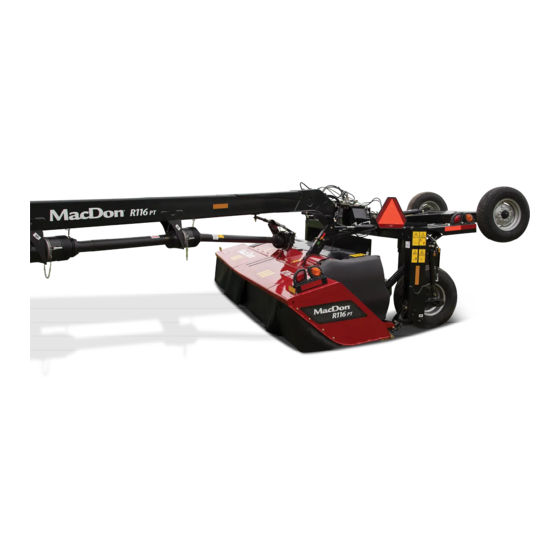
Page 41: Component Identification
PRODUCT OVERVIEW 2.2 Component Identification Figure 2.1: Rotary Disc Pull-Type with Finger Conditioner A - Cutterbar Door B - Header Swivel Gearbox C - Center-Link D - Amber Hazard/Turn Signal Light (x2) E - Red Tail/Brake Light (x2) F - Forward Baffle Control G - Front Curtains H - Driveshield J - Carrier Frame... - Page 42 PRODUCT OVERVIEW Figure 2.3: Rotary Disc Pull-Type with Finger Conditioner A - Optional Transport B - Forming Shield Cover C - Transport Locking Cylinder D - Skid Shoe E - Side Deflector F - Rear Curtain Figure 2.4: Hitch and Driveline — R116 Shown, R113 Similar A - Control Hoses B - Primary Driveline C - Hose Support...
- Page 43 PRODUCT OVERVIEW Figure 2.5: Hitch Options A - Tractor Two-Point Hitch Adapter B - Tractor Drawbar Hitch Adapter C - Tractor Utility Hitch Adapter 215333 Revision A...
-
Page 44: Product Specifications
PRODUCT OVERVIEW 2.3 Product Specifications NOTE: Specifications and design are subject to change without notice or obligation to revise previously sold units. Table 2.1 Rotary Disc Pull-Type Specifications Components R113 R116 Frame and Structure Transport width without Road-Friendly 4063 mm (13 ft. 4 in.) 5027 mm (16 ft. - Page 45 PRODUCT OVERVIEW Table 2.1 Rotary Disc Pull-Type Specifications (continued) Components R113 R116 Cutterbar Quantity of cutting discs Blades per disc Two 18 degrees bevel down reversible Disc speed 2652 rpm Blade tip speed range 303 km/h (188 mph) Effective cutting width 3978 mm (156 5/8 in.) 4942 mm (194 5/8 in.) Cutting height...
- Page 46 PRODUCT OVERVIEW Table 2.1 Rotary Disc Pull-Type Specifications (continued) Components R113 R116 Conditioner – Finger Type Drive 4HB belt driven Conditioner system V-shaped tines on rotating drum Conditioner speed Rotor length 3275 mm (10 ft. 9 in.) Rotor diameter 648 mm (25 1/2 in.) / 152 mm (6 in.) O.D. tube Swath width 915–2896 mm (36–114 in.) Forming shields...
-
Page 47: Chapter 3: Operation
Chapter 3: Operation 3.1 Lift Cylinder Lock-Out Valves To prevent unintentional raising or lowering of the rotary disc pull-type, engage the lift cylinder lock-out valves before servicing, repairing, or unplugging your machine. The lift cylinder lock-out valves are located on the lift cylinders at the back of the rotary disc pull-type. -
Page 48: Disengaging Locks
OPERATION 3.1.2 Disengaging Locks DANGER To avoid bodily injury or death from unexpected start-up or fall of a raised machine, stop engine, remove key, and engage lift cylinder lock-out valves before going under machine for any reason. 1. Open lock-out valve (A) on each lift cylinder by turning the handle to the open position (in line with the hose). -
Page 49: Driveshields
OPERATION 3.2 Driveshields 3.2.1 Opening Driveshields CAUTION To reduce the risk of personal injury, do NOT operate the machine without the driveshields in place and secured. NOTE: Images shown in this procedure are for the left driveshield—the right driveshield is similar. Figure 3.5: Left Driveshield 1. - Page 50 OPERATION 3. Pull top of driveshield (A) away from the header to open. NOTE: For improved access, lift driveshield off the pins at the base of the shield, and lay the shield on the header. Figure 3.8: Driveshield 215333 Revision A...
-
Page 51: Closing Driveshields
OPERATION 3.2.2 Closing Driveshields CAUTION To reduce the risk of personal injury, do NOT operate the machine without the driveshields in place and secured. NOTE: Images shown in this procedure are for the left driveshield—the right driveshield is similar. 1. Position driveshield onto pins at base of driveshield (if necessary). -
Page 52: Cutterbar Doors
OPERATION 3.3 Cutterbar Doors WARNING To reduce the risk of personal injury and machine damage, do NOT operate the machine without all the cutterbar doors down or without curtains installed and in good condition. Foreign objects can be ejected with considerable force when the machine is started. -
Page 53: Opening Cutterbar Doors - Export Latches
OPERATION 3.3.2 Opening Cutterbar Doors – Export Latches Machines sold outside North America require a tool-operated latch on the cutterbar doors. Follow these steps to open cutterbar doors with export latches: WARNING To avoid bodily injury or death from unexpected startup of the machine, always stop the engine and remove the key from the ignition before leaving the operator’s seat for any reason. -
Page 54: Closing Cutterbar Doors
OPERATION 5. Lift up on doors (A) while pressing down on the latch. Figure 3.15: Cutterbar Doors and Curtains 3.3.3 Closing Cutterbar Doors CAUTION To avoid injury, keep hands and fingers away from corners of doors when closing. 1. Pull down on door (A) from the top to close. 2. -
Page 55: Daily Start-Up Check
OPERATION 3.4 Daily Start-Up Check CAUTION • Ensure the tractor and the rotary disc pull-type are properly attached, all controls are in neutral, and the tractor brakes are engaged. • Clear the area of other persons, pets etc. Keep children away from machinery. Walk around the rotary disc pull-type to make sure no one is under, on, or close to it. - Page 56 OPERATION Perform the following checks each day before startup: 1. Check the machine for leaks or any parts that are missing, broken, or not working correctly. NOTE: Use proper procedure when searching for pressurized fluid leaks. Refer to 4.6.1 Checking Hydraulic Hoses and Lines, page 274.
-
Page 57: Preparing Tractor For Rotary Disc Pull-Type
OPERATION 3.5 Preparing Tractor for Rotary Disc Pull-Type 3.5.1 Tractor Requirements The tractor used to pull the rotary disc pull-type must meet the requirements outlined in the following table: Table 3.1 Tractor Requirements Model Number Minimum Power Minimum Drawbar Capacity Minimum Hydraulics R113 PT 75 kW (100 hp) -
Page 58: Setting Up The Rotary Disc Pull-Type Hitch
OPERATION 3.6 Setting up the Rotary Disc Pull-Type Hitch MacDon R1 Series Rotary Disc Pull-Types are factory fitted with either a drawbar or a two-point hitch. Your Dealer will have installed the proper hitch adapter for your tractor. 3.6.1 Installing Drawbar Hitch Adapter IMPORTANT: The hitch adapter is compatible with Class 2 and Class 3 hitches only. -
Page 59: Attaching Rotary Disc Pull-Type To The Tractor
OPERATION 3.7 Attaching Rotary Disc Pull-Type to the Tractor Refer to the attachment procedure that applies to your tractor: • 3.7.1 Attaching with Drawbar Hitch, page 43 • 3.7.2 Attaching with Two-Point Hitch, page 45 3.7.1 Attaching with Drawbar Hitch WARNING To avoid bodily injury or death from the unexpected startup of the machine, always stop the engine and remove the key before making adjustments to the machine. - Page 60 OPERATION 4. Lower the hitch with the jack so that pin (A) engages drawbar hitch adapter (B). 5. Install clevis pin (C) and secure with lynch pin (D). Figure 3.24: Rotary Disc Pull-Type Hitch 6. Position primary driveline (A) onto the tractor power take- off (PTO).
-
Page 61: Attaching With Two-Point Hitch
OPERATION 10. Move jack (A) to storage position on top of hitch, and secure with pin (B). 11. Proceed to 3.7.3 Connecting Hydraulics, page Figure 3.27: Drawbar Jack Storage 3.7.2 Attaching with Two-Point Hitch Follow these steps to attach category II, IIIN, and III two-point hitches: WARNING To avoid bodily injury or death from the unexpected startup of the machine, always stop the engine and remove the key before making adjustments to the machine. - Page 62 OPERATION 6. Check distance (C) between tractor primary power take-off (PTO) shaft (A) and rotary disc pull-type hitch gearbox shaft (B) without the front half of the driveline attached. 7. Ensure that distance (C) does NOT exceed the dimensions listed in Table 3.3, page Table 3.3 Distance between Hitch Gearbox and Tractor PTO Driveline Shaft Size...
- Page 63 OPERATION 14. Rotate stand (A) upward and into storage position. Figure 3.32: Repositioning Hitch Stand 15. Insert pin (A) and secure stand (B) in storage position. Figure 3.33: Hitch Stand in Storage Position 215333 Revision A...
-
Page 64: Connecting Hydraulics
OPERATION 3.7.3 Connecting Hydraulics WARNING Do NOT use remote hydraulic system pressures over 20,684 kPa (3000 psi). Check your tractor operator’s manual for remote system pressure. NOTE: Refer to the numbered/colored bands on the hoses to identify lift, swing/transport, and tilt hose sets. Table 3.4 Hydraulic System Hoses Tractor System... -
Page 65: Connecting Electrical Wiring Harness
OPERATION 3.7.4 Connecting Electrical Wiring Harness 1. Ensure that pin #4 (A) in the tractor receptacle is NOT continuously energized (for instructions, refer to your tractor operator’s manual). If necessary, remove the appropriate fuse. IMPORTANT: Older model tractors may have pin #4 (A) energized as an accessory circuit;... - Page 66 OPERATION If your tractor has a three-pin auxiliary power connection (A): 5. Connect the two wires (B) from the three-pin auxiliary connector to power wires (C) on the control box, wrap connections with electrical tape, and skip to Step 7, page Figure 3.38: Three-Pin Auxiliary Connector If your tractor does not have a three-pin auxiliary power connection: 6.
- Page 67 OPERATION NOTE: The transport control box has a 10 amp fuse (A) inside. If this fuse fails, the transport function will not activate. Figure 3.40: Control Box Interior 7. Place the control box inside the tractor cab. 215333 Revision A...
-
Page 68: Detaching Rotary Disc Pull-Type From Tractor
OPERATION 3.8 Detaching Rotary Disc Pull-Type from Tractor 3.8.1 Detaching from Drawbar CAUTION • To prevent accidental movement of the tractor, shut off the engine, engage the parking brake, and remove the key. • To maintain stability, always lower the machine completely. Block the rotary disc pull-type’s wheels before detaching from tractor. - Page 69 OPERATION 7. Disconnect the hydraulic hoses and electrical harness from the tractor and store the hose ends and electrical connector in hose support (A) at front of hitch as shown. Figure 3.42: Hose Support 8. Pull pin (B) securing jack (A) at storage location and remove the jack.
- Page 70 OPERATION 12. Disconnect safety chain (B) from drawbar and store on the hitch. 13. Pull back collar (A) on the driveline, slide the coupler off the tractor power take-off shaft, and rest the driveline on the hook (not shown). Figure 3.45: Driveline and Jack 14.
-
Page 71: Detaching From Two-Point Hitch
OPERATION 3.8.2 Detaching from Two-Point Hitch WARNING • To prevent accidental movement of tractor, shut off engine, engage parking brake, and remove key. • To maintain stability, always lower the machine completely. Block the Rotary Disc Pull-Type wheels before detaching from tractor. 1. - Page 72 OPERATION 7. Disconnect the hydraulic hoses and the electrical harness. Store the hose ends and the electrical connector at the front of the hitch as shown. NOTE: Control box (A) is also stored at the front of the hitch. Figure 3.49: Front of Hitch 8.
- Page 73 OPERATION 10. Hold stand (A), and pull lock (B) to disengage the stand. Figure 3.52: Hitch Stand and Lock 11. Lower stand (A), rotate lock (C) counterclockwise to horizontal position, and push the lock to engage the stand. 12. Check that stand (A) is locked. 13.
-
Page 74: Breaking In The Rotary Disc Pull-Type
OPERATION 3.9 Breaking in the Rotary Disc Pull-Type After attaching the rotary disc pull-type to the tractor for the first time, operate the machine at low speed for 5 minutes while watching and listening FROM THE OPERATOR’S SEAT for binding or interfering parts. WARNING Before investigating an unusual sound or attempting to correct a problem, shut off tractor, engage parking brake, and remove key. -
Page 75: Engaging The Power Take-Off
OPERATION 3.10 Engaging the Power Take-Off WARNING Be sure all bystanders are clear of the machine before engaging the power take-off (PTO). Never leave tractor seat with the PTO engaged. 1. Move the rotary disc pull-type up to the standing crop, and slowly engage the PTO. 2. -
Page 76: Raising And Lowering The Rotary Disc Pull-Type
OPERATION 3.11 Raising and Lowering the Rotary Disc Pull-Type 3.11.1 Lift Cylinders Two hydraulic cylinders (A), one at each end of the carrier, raise or lower the rotary disc pull-type when the tractor’s cylinder control lever is activated. The lift system is equipped with a lock-out valve (B) at each cylinder which prevents the cylinder from extending or retracting due to accidental movement of the lift control. -
Page 77: Shutdown Procedure
OPERATION 3.12 Shutdown Procedure CAUTION Before leaving the tractor seat for any reason: • Disengage the power take-off. • Park on level ground if possible. • Lower the rotary disc pull-type fully. • Place all controls in NEUTRAL or PARK. •... -
Page 78: Steering The Rotary Disc Pull-Type
OPERATION 3.13 Steering the Rotary Disc Pull-Type IMPORTANT: Valve (A) on the steering line must be in the open position (handle in line with hose) for the steering system to operate. Steering is controlled by the tractor’s remote hydraulic system. The hitch provides the ability to do the following: •... -
Page 79: Operating On The Left Side Of The Tractor
OPERATION 1. Move steering control lever (A) forward to position (B) until the rotary disc pull-type reaches the desired path of travel on the right side of the tractor. Figure 3.60: Tractor Steering Control Lever 3.13.2 Operating on the Left Side of the Tractor Follow the step below to steer the rotary disc pull-type to the left side of the tractor. -
Page 80: Avoiding Obstacles
OPERATION 3.13.3 Avoiding Obstacles Follow the steps below to steer the rotary disc pull-type around an obstacle. Figure 3.63: Rotary Disc Pull-Type Steered around Obstacle 1. Activate steering control lever (A) to steer rotary disc pull- type into the desired path of travel. •... - Page 81 OPERATION IMPORTANT: Ensure that the inside tractor tire does NOT contact the hitch. 4. Position the tractor so it is straddling the last cut windrow. As the rotary disc pull-type finishes turning, steer it back towards the uncut crop, align the rotary disc pull-type with the crop edge, and lower rotary disc pull-type to cutting height.
-
Page 82: Turning 180 Degrees
OPERATION 3.13.5 Turning 180 Degrees NOTE: When cutting back and forth on one side of the field, approximately 15 m (50 ft.) is required at each end of the field to make a 180 degree turn. Figure 3.66: 180 Degree Turn 1. -
Page 83: Transporting The Rotary Disc Pull-Type
OPERATION 3.14 Transporting the Rotary Disc Pull-Type You can transport the rotary disc pull-type using a tractor in either field mode or transport mode. • To prepare a rotary disc pull-type for towing with a tractor in field mode without using the Road-Friendly Transport ™... - Page 84 OPERATION 3. If equipped with a drawbar hitch: Turn the handle on jack stand (A) to raise the stand. Remove pin (B) and stand (A). Figure 3.67: Drawbar Jack in Working Position 4. If equipped with a drawbar hitch: Move jack (A) to the storage position on the side of the hitch, align the mounting holes, and secure with pin (B).
- Page 85 OPERATION 6. If equipped with a two-point hitch: Insert pin (A) and secure stand (B) in storage position. Figure 3.70: Two-Point Hitch Jack in Storage Position 7. Connect the hitch swing cylinder hoses (collars with #2) to tractor’s hydraulic circuit (A). For instructions, refer to 3.7.3 Connecting Hydraulics, page Figure 3.71: Hydraulic Connection...
-
Page 86: Converting Between Field And Transport Modes
OPERATION 11. Close the hitch swing lock-out valve by turning handle (A) to the closed position (90° angle to the hose). 12. Ensure tires are properly inflated. 13. Ensure the slow moving vehicle (SMV) sign, reflectors, and lights are clean and visible at rear of rotary disc pull-type. 14. -
Page 87: Converting From Field To Transport Mode - Without Road-Friendly Transport
OPERATION 4. Open lock-out valve (A) on each lift cylinder by turning the handle to the open position (in line with hose). Figure 3.75: Lift Cylinder Lock-Out Valve in Open Position Converting from Field to Transport Mode – Without Road-Friendly Transport ™... -
Page 88: Converting From Field To Transport Mode - With Road-Friendly Transport
OPERATION 6. Close the lift cylinder lock-out valve by turning handle (A) to the closed position (90° angle to the hose). Repeat on opposite side. 7. Disconnect all hydraulic hoses (refer to 3.7.3 Connecting Hydraulics, page 48 for instructions), and disconnect electrical wiring harness. - Page 89 OPERATION 1. Clear bystanders from the area and start tractor. Do NOT operate the rotary disc pull-type. 2. Following the steps on field-to-transport decal (A), move transport switch to lower position (C) and ensure that light (B) is illuminated. Figure 3.78: Control Box 3.
- Page 90 OPERATION 4. Operate the hitch swing control lever to rotate the rotary disc pull-type to the right until the cam bearing nut is aligned with the green section of the transport alignment gauge decal. Figure 3.80: Rotary Disc Pull-Type Rotation 5.
- Page 91 OPERATION 9. Operate the lift control lever to lower the rotary disc pull- type onto the transport assembly, raise the field wheels, and engage the transport latch onto the hitch. IMPORTANT: Once the latch has engaged, do NOT operate any hydraulic circuits.
- Page 92 OPERATION Lift cylinder lock-out: Close the valve by turning handle (A) to the closed position (90° to the hose). Repeat on opposite side. Figure 3.86: Lift Cylinder Lock-Out Valve 11. Activate hazard lights (A) on the rotary disc pull-type. Ensure all lights are working. 12.
- Page 93 OPERATION 13. Once field-to-transport conversion (A) is complete, leave the switch in upper position (C). Ensure that light (B) is NOT illuminated. Figure 3.88: Control Box 215333 Revision A...
-
Page 94: Converting From Transport To Field Mode - With Road-Friendly Transport
OPERATION Converting from Transport to Field Mode – with Road-Friendly Transport ™ DANGER To prevent serious injury or death, do NOT convert the machine into, or from transport mode until all people, animals, and objects are clear of the unit’s rotational range. CAUTION To prevent injury or equipment damage, ensure cutterbar doors are properly closed before converting the machine from field to transport mode. - Page 95 OPERATION Steering lock-out: Open the valve by turning handle (A) to the open position (in line with the hose). Figure 3.91: Steering Lock-Out Valve Lift cylinder lock-out: Open the valve by turning handle (A) to the open position (in line with the hose). Repeat on opposite side.
- Page 96 OPERATION 5. Operate the hitch swing control lever to rotate the rotary disc pull-type to the right. The rotary disc pull-type will stop when it reaches operating position. NOTE: A sequenced movement transitions the rotary disc pull-type from transport to field mode. This is accomplished by the rear transport swing cylinder, and the transport deploy cylinder.
-
Page 97: Transporting With A Tractor
OPERATION 8. Once transport-to-field conversion (A) is complete, leave the switch in lower position (C). Ensure that light (B) is illuminated. Figure 3.96: Control Box 3.14.3 Transporting with a Tractor Converting from Field to Transport Mode – ™ If towing endwise with the optional Road-Friendly Transport system, refer to ™... -
Page 98: Transport Lighting
OPERATION 4. If equipped with a two-point hitch: Insert pin (A) and secure stand (B) in storage position. Figure 3.98: Two-Point Hitch Jack in Storage Position 5. Ensure the hydraulic hoses are securely stored on the hitch. NOTE: The primary driveline and hydraulic hoses do NOT need to be attached to the tractor for towing. 6. -
Page 99: Lighting - Without Road-Friendly Transport ™ Option
OPERATION Lighting – Without Road-Friendly Transport ™ Option The rotary disc pull-type is equipped with two bidirectional amber lights (A) located on the outboard edges of the carrier frame that function as flashing hazard lights and turn signals. Red lights (B) located on the inboard side of the amber lights function as both tail and brake lights. -
Page 100: Operating The Rotary Disc Pull-Type
OPERATION 3.15 Operating the Rotary Disc Pull-Type Operating the rotary disc pull-type properly results in less crop lost and increased productivity during harvest. This includes making proper adjustments while operating the machine to suit various crops and harvest conditions. Regular maintenance and operating the machine safely and properly increases the machine’s length of service. - Page 101 OPERATION 1. Center the rotary disc pull-type directly behind the tractor and set the cutterbar to an appropriate orientation and tilt for the crop type and cutting conditions. Refer to 3.15.3 Adjusting Cutterbar Angle, page 90 for instructions. NOTE: Ensure skid shoes are in correct position before setting rotary disc pull-type angle, float, and tilt.
- Page 102 OPERATION 7. Turn adjuster bolt (A) to achieve the recommended measurement (B) for the conditioner type. Refer to Table 3.9, page 86 for measurements. NOTE: Float settings indicated in the table are starting points only. Float force should still be checked with the rotary disc pull- type float and cutting angle set as planned for use in the field.
-
Page 103: Cutting Height
OPERATION 9. Open lift cylinder lock-out valve (A) on each cylinder by turning the handle to the open position (in line with the hose). 10. To check float, lower the rotary disc pull-type to cutting position, grasp the front corner of the rotary disc pull-type, and lift;... -
Page 104: Adjusting Cutting Height
OPERATION Adjusting Cutting Height DANGER To avoid bodily injury or death from unexpected start-up or fall of a raised machine, stop engine, remove key, and engage lift cylinder lock-out valves before going under machine for any reason. NOTE: There are two skid shoes on the R113 PT, and four on the R116 PT. 1. - Page 105 OPERATION Figure 3.108: Skid Shoes – R116 PT 215333 Revision A...
-
Page 106: Adjusting Cutterbar Angle
OPERATION 3.15.3 Adjusting Cutterbar Angle The cutterbar angle (A) adjustment ranges from 0° to 5° below horizontal using the mechanical center-link and from 0° to 7° below horizontal using the hydraulic center-link. Choose an angle that maximizes performance for your crop and field conditions. -
Page 107: Ground Speed
OPERATION 1. Start the engine. 2. Lower the rotary disc pull-type fully. 3. Decrease (flatten) the cutterbar angle by operating the tractor hydraulic control so that cylinder (C) retracts and moves gauge (D) toward the green zone (A). 4. Increase (steepen) the cutterbar angle by operating the tractor hydraulic control so that cylinder (C) extends and moves gauge (D) toward the red zone (B). - Page 108 OPERATION Figure 3.112: Ground Speed for R113 and R116 PT A - Acres/Hour B - Hectares/Hour C - Kilometers/Hour D - Miles/Hour E - R116 PT F - R113 PT 215333 Revision A...
-
Page 109: Cutterbar Deflectors
OPERATION 3.15.5 Cutterbar Deflectors A two-piece cutterbar deflector is attached to the cutterbar just below the conditioner rolls. Deflectors provide improved feeding into the conditioner rolls and prevent heavy crop with long stems from feeding under the rolls. Cutterbar deflectors may not be well-suited for some crop and field conditions. Refer to the following table: Table 3.10 Conditions for Using Cutterbar Deflectors Use Deflector Crop/Field Condition... -
Page 110: Installing Cutterbar Deflectors
OPERATION Installing Cutterbar Deflectors The cutterbar deflectors are used with roll conditioners only. DANGER To avoid bodily injury or death from unexpected start-up or fall of a raised machine, stop engine, remove key, and engage lift cylinder lock-out valves before going under machine for any reason. 1. -
Page 111: Removing Tall Crop Divider
OPERATION 1. Lower the rotary disc pull-type fully. 2. Shut down the engine, and remove the key from the ignition. 3. Open the cutterbar doors. For instructions, refer to 3.3.1 Opening Cutterbar Doors – North America, page 36 3.3.2 Opening Cutterbar Doors – Export Latches, page Figure 3.115: Cutterbar Doors 4. - Page 112 OPERATION 4. Remove three bolts (A), and remove deflector (B). 5. Reinstall three bolts (A). 6. Repeat for opposite side. 7. Close cutterbar doors. For instructions, refer to 3.3.3 Closing Cutterbar Doors, page Figure 3.118: Deflector and Hardware 215333 Revision A...
-
Page 113: Conditioning: Roll Type
OPERATION 3.16 Conditioning: Roll Type Rolls condition the crop by crimping and crushing the stem in several places allowing the release of moisture, resulting in faster drying times. Both steel and polyurethane conditioner rolls are available. 3.16.1 Roll Gap The roll gap controls the degree to which crop is conditioned as it passes through the rolls. Roll gap is factory-set at approximately 3 mm (1/8 in.) for polyurethane rolls, and at 6 mm (1/4 in.) for steel rolls. - Page 114 OPERATION 4. Steel Roll: The length of thread (A) extending above the jam nut on the adjustment rods can be used as an approximation of roll gap but does NOT provide consistent roll gap measurements. Roll gap factory setting is 6 mm (1/4 in.).
-
Page 115: Adjusting Roll Gap - Polyurethane Rolls
OPERATION Adjusting Roll Gap – Polyurethane Rolls Because polyurethane rolls operate at smaller gaps and the conditioning is less aggressive, the roll gap setting is more sensitive than on steel rolls. To return roll gap to the factory setting, follow the procedure below: WARNING To avoid injury or death from unexpected start-up of machine, always stop the engine and remove the key from the ignition before leaving the operator’s seat for any reason. -
Page 116: Adjusting Roll Gap - Steel Rolls
OPERATION Adjusting Roll Gap – Steel Rolls The length of thread extending above the jam nut on the adjustment rods can be used as an approximation of roll gap but does NOT provide consistent roll gap measurements. To ensure the roll gap is at the factory setting, follow the procedure below: WARNING To avoid injury or death from unexpected start-up of machine, always stop the engine and remove the key from the... -
Page 117: Roll Tension
OPERATION 3.16.2 Roll Tension Roll tension (the pressure holding the rolls together) is factory-set to maximum and should rarely require adjustment. Heavy crops or tough forage can cause the rolls to separate; therefore, maximum roll tension is required to ensure that materials are sufficiently crimped. -
Page 118: Checking Roll Timing
OPERATION Checking Roll Timing Check roll timing if excessive noise is coming from the conditioner rolls. Roll timing is factory-set and should not require adjustment; however, if there is excessive noise coming from the conditioner rolls, the timing will need to be adjusted. For instructions, refer to Adjusting Roll Timing, page 102. - Page 119 OPERATION 6. Manually rotate upper roll (A) in a clockwise direction until it stops. Make a second mark (B) on the yoke flange, and align it with the mark on the gearbox flange. Figure 3.127: Conditioner Drive 7. Determine center point (A) between the two marks on the yoke plate, and place a third mark.
-
Page 120: Adjusting Forming Shields - Roll Conditioner
OPERATION 9. Ensure the threads on four bolts (A) are clean and free of lubricant. NOTE: Only three of the four bolts are shown in the illustration. ® 10. Apply medium-strength threadlocker (Loctite 242 or equivalent), and tighten bolts (A). Torque to 95 Nm (70 lbf·ft). - Page 121 OPERATION 1. Loosen locking handle (A). 2. Slide adjuster bar (B) along adjuster plate (C) to the desired deflector position and engage bar (B) into a notch in the adjuster plate. 3. Tighten locking handle (A). 4. Repeat for the other side. Figure 3.130: Side Deflector and Adjuster Bar 215333 Revision A...
-
Page 122: Positioning Rear Baffle - Roll Conditioner
OPERATION Positioning Rear Baffle – Roll Conditioner The rear baffle is used in conjunction with the forming shields to determine the height and width of the windrow. It is located immediately behind and above the conditioning rolls and can be positioned to do the following: •... -
Page 123: Conditioning - Finger Type
OPERATION 3.17 Conditioning – Finger Type The finger type conditioner is used to harvest light grass crops. The finger type rotor moves the crop across the conditioning baffle which strips away the waxy coating from the plants. Do not use the finger type conditioner for thick- stemmed crops such as sudan and milo, or for heavy crops. -
Page 124: Finger Rotor Speed
OPERATION 3.17.2 Finger Rotor Speed The finger rotor is set to 900 rpm at the factory, but it can be changed to 600 rpm depending on crop conditions, crop volume, and the desired amount of conditioning. In sensitive crops, 600 rpm may be a suitable speed to minimize crop damage. In light crops and dry grasses, 900 rpm may be a more effective speed. - Page 125 OPERATION 4. Measure and record the distance from the shaft end to taper lock bushing face (A) on both pulleys. 5. Remove three bolts (B) and insert them into the three threaded bores. 6. Apply uniform pressure to the taper lock bushing by slightly tightening each bolt in a circular pattern until the taper lock bushing comes free.
- Page 126 OPERATION 15. Measure the length of tensioner spring (A), and turn adjuster nut (B) to adjust spring length to 36.5 cm (14 3/8 in.) to conform with spring tension decal (C). Figure 3.138: Spring Tension Decal 16. Install jam nut (A). 17.
-
Page 127: Forming Shields - Finger Conditioner
OPERATION 3.17.3 Forming Shields – Finger Conditioner The position of the forming shields controls the width and placement of the windrow. Decide which forming shield position to use based on the following factors: • Weather conditions (rain, sun, humidity, wind) •... -
Page 128: Positioning Rear Baffle - Finger Conditioner
OPERATION Positioning Rear Baffle – Finger Conditioner The rear baffle (A) is located immediately behind and above the finger conditioner. Baffle (A) can be used to direct crop into the forming shields for narrow and moderate width windrows or to direct crop downward to form a wide swath. -
Page 129: Haying Tips
OPERATION 3.18 Haying Tips 3.18.1 Curing Curing crops quickly helps maintain the highest quality of crop material as 5% of protein is lost from hay for each day that it lays on the ground after cutting. Leaving the windrow as wide and fluffy as possible results in the quickest curing. Cured hay should be baled as soon as possible. -
Page 130: Windrow Characteristics
OPERATION 3.18.4 Windrow Characteristics Producing windrows with the recommended characteristics will achieve the best results. Refer to 3.15 Operating the Rotary Disc Pull-Type, page 84 for instructions on adjusting the rotary disc pull-type. Table 3.12 Recommended Windrow Characteristics Characteristic Advantage Enables airflow through windrow, which is more important to the curing High and fluffy process than direct sunlight... -
Page 131: Checking Level Of The Rotary Disc Pull-Type
If the rotary disc pull-type is NOT level, check the tire pressure and ensure proper inflation. For inflation instructions refer Inflating Tires, page 273. Component damage in the rotary disc pull-type support system may occur if the rotary disc pull-type cannot be leveled. Contact your MacDon Dealer. 215333 Revision A... -
Page 132: Unplugging The Rotary Disc Pull-Type
OPERATION 3.20 Unplugging the Rotary Disc Pull-Type The cutterbar or the conditioner rolls (if installed) can get plugged with crop. To safely unplug the cutterbar, follow these steps: WARNING To avoid injury or death from unexpected start-up of machine, always stop the engine and remove the key from the ignition before leaving the operator’s seat for any reason. - Page 133 OPERATION 7. Close cutterbar doors. For instructions, refer to 3.3.3 Closing Cutterbar Doors, page Figure 3.145: Cutterbar Doors in Closed Position 215333 Revision A...
-
Page 135: Chapter 4: Maintenance And Servicing
Chapter 4: Maintenance and Servicing The following instructions provide information about routine servicing for the rotary disc pull-type. A parts catalog is located in a plastic case at the right end of the rotary disc pull-type. Log hours of operation and use the maintenance record provided (refer to 4.3.1 Maintenance Schedule/Record, page 123) to keep track of your scheduled maintenance. - Page 136 MAINTENANCE AND SERVICING • Be aware that if more than one person is servicing the machine at the same time, rotating a driveline or other mechanically driven component by hand (for example, to access a lube fitting) will cause drive components in other areas (belts, pulleys, and discs) to move.
-
Page 137: Preparing Machine For Servicing
MAINTENANCE AND SERVICING 4.2 Preparing Machine for Servicing CAUTION To avoid personal injury, perform the following procedures before servicing rotary disc pull-type or opening drive covers: 1. Lower the rotary disc pull-type fully. If you need to perform service in the raised position, and always close lift cylinder lock-out valves. -
Page 138: Maintenance Requirements
MAINTENANCE AND SERVICING 4.3 Maintenance Requirements IMPORTANT: Recommended intervals are for average conditions. Service the machine more often if operating under adverse conditions (severe dust, extra heavy loads, etc.). Regular maintenance is the best insurance against early wear and untimely breakdowns. Following the maintenance schedule will increase your machine’s life. -
Page 139: Maintenance Schedule/Record
MAINTENANCE AND SERVICING 4.3.1 Maintenance Schedule/Record Keep a record of maintenance as evidence of a properly maintained machine. Daily maintenance records are not required to meet normal warranty conditions. Hour meter reading Service date Serviced by First use Refer to 4.3.2 Break-In Inspections, page 127. - Page 140 MAINTENANCE AND SERVICING Check header swivel gearbox and hitch swivel gearbox lubricant. Refer to ü Checking Lubricant Levels in the Header Swivel Gearbox and Hitch Swivel Gearbox , page 268. Check cutterbar-conditioner drive gearbox lubricant. Refer to Checking and ü Adding Lubricant –...
- Page 141 MAINTENANCE AND SERVICING Change header swivel gearbox and hitch swivel gearbox lubricant. Refer to Draining Lubricant from the Header ▲ Swivel Gearbox and Hitch Swivel Gearbox , page 269 Adding Lubricant to the Header Swivel Gearbox and Hitch Swivel Gearbox , page 270.
- Page 142 MAINTENANCE AND SERVICING Change cutterbar-conditioner drive gearbox lubricant. Refer to Draining Rotary Disc Pull-Type Gearbox ▲ (T-Gearbox) Lubricant, page 263 Checking and Adding Lubricant – Cutterbar-Conditioner Drive Gearbox (T-Gearbox), page 261. Change header swivel gearbox and hitch swivel gearbox lubricant. Refer to Draining Lubricant from the Header ▲...
-
Page 143: Break-In Inspections
MAINTENANCE AND SERVICING 4.3.2 Break-In Inspections Table 4.1 Break-In Inspection Schedule Inspection Item Refer to Interval Check wheel bolts Checking Wheel Bolts, page 270 Hour Check clutch operation and slippage Checking Clutch Operation, page 241 Hour Check for loose hardware and tighten 7.1 Torque Specifications, page 309 Hours to required torque... -
Page 144: End-Of-Season Servicing
MAINTENANCE AND SERVICING 3. Perform all annual maintenance as listed in 4.3.1 Maintenance Schedule/Record, page 123. 4.3.4 End-of-Season Servicing CAUTION Never use gasoline, naphtha, or any volatile material for cleaning purposes. These materials may be toxic and/or flammable. CAUTION Cover cutterbar to prevent injury from accidental contact. Perform the following procedures at the end of each operating season: 1. -
Page 145: Greasing Procedure
MAINTENANCE AND SERVICING Greasing points are marked on the machine by decals showing a grease gun and the grease interval in hours of operation. Log hours of operation and use the maintenance schedule provided to keep a record of scheduled maintenance. Refer to 4.3.1 Maintenance Schedule/Record, page 123. - Page 146 MAINTENANCE AND SERVICING Every 25 Hours Figure 4.7: Grease Location (Every 25 Hours) 3x25 3x25 A - Conditioner Drive Idler B - Bearing for Finger-Type Conditioner 215333 Revision A...
- Page 147 MAINTENANCE AND SERVICING Figure 4.8: Grease Location (Every 25 Hours) A - Hitch Steering Pivot B - Tractor Hitch Pivot 215333 Revision A...
- Page 148 MAINTENANCE AND SERVICING NOTE: It may be necessary to remove and replace the driveline shield cones during the greasing procedure. Refer to 4.5.2 Driveline Shield Cone, page 223 for more information. NOTE: Use high temperature extreme pressure (EP2) performance with 10% max molybdenum disulphide (NLGI Grade 2) lithium base unless otherwise specified.
- Page 149 MAINTENANCE AND SERVICING Figure 4.10: Grease Location (Every 25 Hours) ™ ™ ™ ™ A - Road Friendly Transport Casting Pivot B - Road Friendly Transport Wheel Frame Pivot Figure 4.11: Grease Location (Every 25 Hours) A - Pull-Type Lift Linkage – Left B - Pull-Type Lift Linkage –...
- Page 150 MAINTENANCE AND SERVICING Every 50 Hours NOTE: Use high temperature extreme pressure (EP2) performance with 1% max molybdenum disulphide (NLGI grade 2) lithium base unless otherwise specified. Figure 4.12: Grease Location (Every 50 Hours) 215333 Revision A...
- Page 151 MAINTENANCE AND SERVICING Every 100 Hours NOTE: Ensure top of hitch and rotary disc pull-type are horizontal, remove check plug from swivel gearbox, and verify that oil slightly runs out when removed. Figure 4.13: Lubrication Location (Every 100 Hours) A - Check Plug - Swivel Gearbox B - Check Plug - Swivel Gearbox C - Check Plug - Swivel Gearbox D - Check Plug - Swivel Gearbox...
- Page 152 MAINTENANCE AND SERVICING Figure 4.14: Lubrication Location (Every 100 Hours) A - Check Plug - Cutterbar-Conditioner Drive Gearbox (T-Gearbox) 12 B - Bearing - Field Wheel (2 Places) 13 ™ ™ C - Bearing - Road Friendly Transport Option (2 Places) 12.
- Page 153 MAINTENANCE AND SERVICING Every 250 Hours 1. Change lubricant in locations (A), (B), and (C). Refer to the following sections for more information: • 4.4.3 Lubricating Cutterbar, page 146. • Checking and Changing Oil in Conditioner Roll Timing Gearbox , page 259.
- Page 154 MAINTENANCE AND SERVICING 2. Change lubricant in hitch swivel gearboxes (A), (B), (C), and (D). For information, refer to 4.5.13 Header Swivel Gearbox and Hitch Swivel Gearbox, page 267. Figure 4.16: Lubrication Location (Every 250 Hours) A - Upper Forward Gearbox B - Lower Forward Gearbox C - Upper Rear Gearbox D - Lower Rear Gearbox...
-
Page 155: Cutterbar System
MAINTENANCE AND SERVICING 4.4 Cutterbar System The cutterbar (A) comes in two cutting widths – 3.9 m (13 ft.) and 4.9 m (16 ft.). The 3.9 m (13 ft.) holds eight discs and the 4.9 m (16 ft.) holds ten discs that rotate to a maximum of 2500 rpm at full engine speed. -
Page 156: Maintaining Curtains
MAINTENANCE AND SERVICING 4.4.2 Maintaining Curtains Rubber curtains are installed at the following locations: • Inboard curtain (A) attached to the center fixed cover • Door curtains (B) attached to each cutterbar door • Outboard curtains (C) attached to each front corner •... -
Page 157: Removing Cutterbar Door Curtains
Opening Cutterbar Doors – North America, page 36 3.3.2 Opening Cutterbar Doors – Export Latches, page Figure 4.21: R1 Series Rotary Disc Pull-Type 2. Remove seven nuts (A) from the bolt studs. 3. Remove aluminum liner (B). 4. Remove curtain (C). -
Page 158: Removing Cutterbar Inboard Curtain
1. Open cutterbar doors. For instructions, refer to 3.3.1 Opening Cutterbar Doors – North America, page Figure 4.24: Cutterbar Doors — R1 Series Rotary Disc Pull-Type 2. Remove two M10 carriage head bolts (A) and nuts securing curtain assembly (B) to the pull-type, and remove curtain assembly. -
Page 159: Installing Cutterbar Inboard Curtain
1. Open cutterbar doors. For instructions, refer to 3.3.1 Opening Cutterbar Doors – North America, page Figure 4.27: Cutterbar Doors — R1 Series Rotary Disc Pull-Type 2. Install curtain onto weld and bolt studs on center shield, install two curtain brackets (B), and secure with four nuts (A). -
Page 160: Removing Outboard Curtains
1. Open cutterbar doors. For instructions, refer to 3.3.1 Opening Cutterbar Doors – North America, page Figure 4.30: Cutterbar Doors — R1 Series Rotary Disc Pull-Type 2. Remove four bolts (A), nuts, and large washers securing outboard curtain to endsheet. -
Page 161: Installing Outboard Curtains
The procedure for installing outboard curtains is the same for both sides. 1. Open cutterbar doors. For instructions, refer to 3.3.1 Opening Cutterbar Doors – North America, page Figure 4.33: Cutterbar Doors — R1 Series Rotary Disc Pull-Type 215333 Revision A... -
Page 162: Lubricating Cutterbar
MAINTENANCE AND SERVICING 2. Install curtain (A) into bracket (B). 3. Install two nuts (D) and tighten. 4. Slide bracket (B) into position, and install the square neck carriage head bolt and flange nut (C). 5. Torque flange nut (C) to 39 Nm (29 lbf·ft). Figure 4.34: Outboard Curtain 6. - Page 163 5. Open cutterbar doors. For instructions, refer to 3.3.1 Opening Cutterbar Doors – North America, page Figure 4.36: Cutterbar Doors – R1 Series Rotary Disc Pull-Type 6. Use a spirit (bubble) level (A) to ensure the cutterbar is level in both directions. Adjust position accordingly.
- Page 164 MAINTENANCE AND SERVICING 7. Clean area around plug (A). Place a 5 liter (5.2 US qts) capacity container under plug (A). 8. Use a 17 mm socket to remove plug (A) and O-ring (B) from cutterbar. Oil level must be up to the inspection plug hole. NOTE: If additional lubricant is required, proceed to Step 9, page...
-
Page 165: Draining The Cutterbar
MAINTENANCE AND SERVICING 20. Close cutterbar doors. For instructions, refer to 3.3.3 Closing Cutterbar Doors, page Figure 4.40: Cutterbar Doors Draining the Cutterbar WARNING To avoid injury or death from unexpected start-up of machine, always stop the engine and remove the key from the ignition before leaving the operator’s seat for any reason. - Page 166 MAINTENANCE AND SERVICING 6. Place a 10 liter (10.5 US qts) capacity container under lower end of cutterbar, clean area around plug (A), and remove plug. IMPORTANT: Do NOT remove hex head bolts (B) securing cutterbar end plate to cutterbar or lubricant leaks could result. 7.
-
Page 167: Filling Lubricant Into A Repaired Cutterbar
MAINTENANCE AND SERVICING Filling Lubricant into a Repaired Cutterbar This procedure should be used when the cutterbar has been completely drained of oil. If you are checking oil level or Checking and Adding Lubricant – Cutterbar, page topping it up, refer to 146. -
Page 168: Cutterbar Discs
MAINTENANCE AND SERVICING 4.4.4 Cutterbar Discs Figure 4.43: Interchangeable Cutterbar Discs Cutterbar discs (A) are interchangeable and can be moved to a spindle that rotates in the opposite direction as long as the disc is in usable condition and the blades are oriented to cut in the correct direction. Perform daily inspections to ensure that cutterbar discs have not suffered damage from rocks, or experienced excessive wear from abrasive working conditions. -
Page 169: Removing Cutterbar Discs
MAINTENANCE AND SERVICING 1. Inspect cutterbar disc for any deformity on the side of the disc blades. Dimension (A) must not exceed 48 mm (1 7/8 in.). Replace as required. NOTE: Dimension (A) is between cutterbar and edge of disc as shown. - Page 170 4. Open cutterbar doors. For instructions, refer to 3.3.1 Opening Cutterbar Doors – North America, page Figure 4.47: Cutterbar Doors – R1 Series Rotary Disc Pull-Type 5. Place a pin (or equivalent) in the front hole of the rock guard (B) to prevent disc rotation while loosening bolts.
-
Page 171: Installing Cutterbar Discs
MAINTENANCE AND SERVICING 7. Remove cutterbar disc cap (A). 8. Remove cutterbar disc (B). Figure 4.49: Cutterbar Disc and Cap Installing Cutterbar Discs DANGER To avoid bodily injury or death from unexpected start-up or fall of a raised machine, stop engine, remove key, and engage lift cylinder lock-out valves before going under machine for any reason. - Page 172 5. Remove pin (or equivalent) from front hole of rock guard. 6. Close cutterbar doors. For instructions, refer to 3.3.3 Closing Cutterbar Doors, page Figure 4.52: Cutterbar Doors — R1 Series Rotary Disc Pull-Type 215333 Revision A...
-
Page 173: Replacing Cutterbar Spindles
MAINTENANCE AND SERVICING 4.4.5 Replacing Cutterbar Spindles To prevent damage to the cutterbar and drive systems, each disc is attached to a spindle containing a shear pin (A). If the disc contacts a large object such as a stone or stump, the pin will shear and the disc will stop rotating and move upwards while remaining attached to the spindle with a snap ring (B). -
Page 174: Removing Cutterbar Spindles
4. Open cutterbar doors. For instructions, refer to 3.3.1 Opening Cutterbar Doors – North America, page Figure 4.55: Cutterbar Doors – R1 Series Rotary Disc Pull-Type 5. Place a pin (or equivalent) in the front hole of rock guard (B) to prevent disc rotation while loosening bolts. - Page 175 MAINTENANCE AND SERVICING 7. Remove cutterbar disc cap (A). 8. Remove cutterbar disc (B). IMPORTANT: Blades are rotation specific. Switch entire disc when swapping spindles. Figure 4.57: Cutterbar Disc and Cap 9. Remove spacer plate (A). Figure 4.58: Spacer Plate 10.
-
Page 176: Installing Cutterbar Spindles
MAINTENANCE AND SERVICING 11. Remove spindle (A) from cutterbar. Figure 4.60: Left Spindle Installing Cutterbar Spindles Figure 4.61: Underside of Cutterbar Spindles IMPORTANT: Right discs (A) and left discs (B) are timed and must be at a 90° angle from adjacent discs when reinstalled. Misaligned discs could result in the following: •... - Page 177 MAINTENANCE AND SERVICING NOTE: Right discs (A) and left discs (B) are slightly offset as shown, depending on which idler gear the spindle is turning: • Spindles that rotate clockwise have left-leading threading • Spindles that rotate counterclockwise have right-leading threading DANGER To avoid bodily injury or death from unexpected start-up or fall of a raised machine, stop engine, remove key, and engage lift cylinder lock-out valves before going under machine for any reason.
- Page 178 MAINTENANCE AND SERVICING 6. Insert spindle (A) into cutterbar. Figure 4.64: Left Spindle 7. Insert studs (A) into spindle as shown. NOTE: Plugs are factory-installed as shown in position (B), but may come loose over time. Ensure studs are inserted into proper location.
- Page 179 MAINTENANCE AND SERVICING 10. Torque bolts to 50 Nm (37 lbf·ft) following the tightening pattern shown at right. NOTE: Hub removed from illustration for clarity. Figure 4.67: Tightening Pattern 11. Install spacer plate (A). Figure 4.68: Spacer Plate 12. Place a pin (or equivalent) in the front hole of the rock guard (D) to prevent disc rotation while tightening bolts.
-
Page 180: Reconfiguring Cutterbar Crop Stream
16. Close cutterbar doors. For instructions, refer to 3.3.3 Closing Cutterbar Doors, page Figure 4.70: R1 Series Rotary Disc Pull-Type 4.4.6 Reconfiguring Cutterbar Crop Stream Discs are factory-installed to produce three crop streams, but disc rotation pattern can be changed by substituting the spindle and corresponding disc to suit crop conditions. - Page 181 MAINTENANCE AND SERVICING IMPORTANT: • Spindles that rotate clockwise have right-leading threading and are identified by a smooth top on the spindle gear shaft (A). • Spindles that rotate counterclockwise have left-leading threading and are identified by machined grooves on the spindle gear shaft (B) and nut (C).
-
Page 182: Changing R113 Pt Cutterbar Crop Stream Configuration
MAINTENANCE AND SERVICING Changing R113 PT Cutterbar Crop Stream Configuration Figure 4.73: R113 PT (8 Disc) Spindle Rotation Pattern and Crop Streams A - One Crop Stream B - Three Crop Streams NOTE: Refer to Removing Cutterbar Spindles, page 158 Installing Cutterbar Spindles, page 160. -
Page 183: Changing R116 Pt Cutterbar Crop Stream Configuration
MAINTENANCE AND SERVICING Changing R116 PT Cutterbar Crop Stream Configuration Figure 4.74: R116 PT (10 Disc) Spindle Rotation Pattern and Crop Streams A - One Crop Stream B - Three Crop Streams NOTE: Refer to Removing Cutterbar Spindles, page 158 Installing Cutterbar Spindles, page 160. -
Page 184: Inspecting Disc Blades
MAINTENANCE AND SERVICING Inspecting Disc Blades WARNING To avoid bodily injury or death from unexpected startup of the machine, always stop the engine and remove the key from the ignition before leaving the operator’s seat for any reason. CAUTION Disc blades have two sharp cutting edges that can cause serious injury. Exercise caution and wear gloves when working with blades. -
Page 185: Inspecting Disc Blade Hardware
MAINTENANCE AND SERVICING Figure 4.78: Clockwise Disc Rotation Inspecting Disc Blade Hardware CAUTION Damaged or loose disc blades or blade attachment hardware can be ejected during machine operation and may cause personal injury or machine damage. Inspect blade attachment hardware each time blades are changed. For instructions, refer to Removing Disc Blades, page Installing Disc Blades, page 172 for hardware replacement procedure. - Page 186 MAINTENANCE AND SERVICING 1. Check and replace bolt if: • Bolt has been removed and installed five times • Head (A) is worn flush with bearing surface of blade • Diameter of bolt neck is worn (B) 3 mm (1/8 in.) •...
-
Page 187: Removing Disc Blades
2. Engage lift cylinder lock-out valves. For instructions, refer to 3.1.1 Engaging Locks, page 3. Open cutterbar doors. For instructions, refer to 3.3.1 Opening Cutterbar Doors – North America, page Figure 4.81: R1 Series Rotary Disc Pull-Type 215333 Revision A... -
Page 188: Installing Disc Blades
MAINTENANCE AND SERVICING 4. Rotate disc (A) so blade (B) faces forward and lines up with hole (C) in rock guard. Figure 4.82: Disc Blade Aligned with Hole in Rock Guard 5. Place a pin (or equivalent) in the front hole of the rock guard to prevent disc rotation while loosening blade bolts. -
Page 189: Maintaining Quick Change Blade System
4. Close cutterbar doors. For instructions, refer to 3.3.3 Closing Cutterbar Doors, page Figure 4.85: R1 Series Rotary Disc Pull-Type 4.4.8 Maintaining Quick Change Blade System The following topics outline maintenance procedures for the optional Quick Change Blade (QCB) system. - Page 190 MAINTENANCE AND SERVICING • Material thickness of retaining bolts (A) must NOT be less than 14 mm (9/16 in.) (C) at the narrowest point. • Material thickness at the quick change plate must NOT be less than 3 mm (1/8 in.) (D) at the narrowest point. Figure 4.86: Retaining Bolt and Quick Change Plate A - Retaining Bolt B - 17 mm (11/16 in.)
-
Page 191: Inspecting Quick Change Plates
MAINTENANCE AND SERVICING Inspecting Quick Change Plates The material thickness of the retaining bolts and the quick change plate is checked using the supplied gauge. DANGER To avoid serious injury or death due to worn quick change plate, check the plates for damage before and after each use. -
Page 192: Replacing Quick Change Blades
MAINTENANCE AND SERVICING NOTE: • If the outer radius of quick change plate (B) aligns with or is outside the outer radius of gauge (A), the quick change plate has not yet reached its wear limit. • If the outer radius of the quick change plate (B) does NOT align with the outer radius of gauge (A), the quick change plate must be replaced. - Page 193 MAINTENANCE AND SERVICING IMPORTANT: Check that blade change tool (A) is fully engaged on both sides of disc (B). Figure 4.94: Correct Positioning of Quick Change Tool 5. Pull down on tool (A) open disc (B) and remove old blade (D) from blade bolt (E). Push tool (A) upward to return disc (B) to the closed position.
-
Page 194: Maintaining Accelerators
MAINTENANCE AND SERVICING 4.4.9 Maintaining Accelerators Accelerators (A) are mounted on each outboard disc and are designed to quickly move cut material off the disc and into the conditioner. One pair of accelerators is installed at each outboard end of an R113 PT, whereas an R116 PT has two pairs at each end. -
Page 195: Removing Accelerators
MAINTENANCE AND SERVICING 5. Inspect accelerators (A) for damage and wear, and replace if worn to 50% or more of their original height or if they are no longer effectively moving crop. 6. Tighten or replace loose or missing fasteners. Figure 4.98: R113 PT Cutterbar Accelerators Figure 4.99: R116 PT Cutterbar Accelerators Removing Accelerators... - Page 196 4. Open cutterbar doors. For instructions, refer to 3.3.1 Opening Cutterbar Doors – North America, page Figure 4.100: R1 Series Rotary Disc Pull-Type CAUTION Disc blades have two sharp cutting edges that can cause serious injury. Exercise caution and wear gloves when working with blades.
-
Page 197: Installing Accelerators
MAINTENANCE AND SERVICING Installing Accelerators DANGER To avoid bodily injury or death from unexpected start-up or fall of a raised machine, stop engine, remove key, and engage lift cylinder lock-out valves before going under machine for any reason. CAUTION Disc blades have two sharp cutting edges that can cause serious injury. Exercise caution and wear gloves when working with blades. -
Page 198: Rock Guards
8. Close cutterbar doors. For instructions, refer to 3.3.3 Closing Cutterbar Doors, page Figure 4.106: R1 Series Rotary Disc Pull-Type 4.4.10 Rock Guards The machine is equipped with rock guards at each cutting disc location. Rock guards prevent the cutterbar from digging into the ground and protect the disc from coming in contact with stones and other debris. -
Page 199: Removing Inboard Rock Guards
MAINTENANCE AND SERVICING 4. Inspect rock guards for wear, cracks, damage, or distortion. Replace if worn to 75% or more of their original thickness. 5. Check for loose or missing fasteners; tighten or replace fasteners as needed. Figure 4.107: Rock Guards Removing Inboard Rock Guards 1. -
Page 200: Installing Inboard Rock Guards
MAINTENANCE AND SERVICING Installing Inboard Rock Guards 1. Guide inboard rock guard onto cutterbar until tabs (A) sit on top of the cutterbar and bottom back bolt holes line up. Figure 4.110: Inboard Rock Guards 2. Install two hex head screws, washers, and lock nuts (A). Torque hardware to 68 Nm (50 lbf·ft). -
Page 201: Installing Outboard Rock Guards
MAINTENANCE AND SERVICING 4. Locate rock guard (B) on the bottom outboard end of the cutterbar. There is one guard on each end of the cutterbar. 5. Remove the two hex head screws (A), washers, and lock nuts (C) securing rock guard (B) to the cutterbar assembly. Figure 4.112: Left Outboard Rock Guard –... - Page 202 MAINTENANCE AND SERVICING ® 5. Apply medium-strength threadlocker (Loctite 242 or equivalent) to bolt (B). NOTE: Some parts removed for clarity. 6. Install bolt (B) with washer onto the cutterbar. 7. Angle rock guard (A) outward as shown. Align the slot in the side plate between the washer and the cutterbar on rear M16 bolt (B).
-
Page 203: Maintaining Small Drums - R116 Pt
MAINTENANCE AND SERVICING ® 11. Apply medium-strength threadlocker (Loctite 242 or equivalent) on two hex head screws (C). Loosely install with lock nuts. 12. Install the M16 x 60 bolt (A) (MD #136141) and one washer (B) as shown. Torque bolts (A) and (D) to 251 Nm (185 lbf·ft). - Page 204 MAINTENANCE AND SERVICING 1. Lower the rotary disc pull-type fully. 2. Shut down the engine, and remove the key from the ignition. 3. Open cutterbar doors (A). For instructions, refer to 3.3.1 Opening Cutterbar Doors – North America, page Figure 4.119: Cutterbar Doors 4.
-
Page 205: Removing Small Driven Drum And Driveline - R116 Pt
MAINTENANCE AND SERVICING 7. Close cutterbar doors (A). For instructions, refer to 3.3.3 Closing Cutterbar Doors, page Figure 4.122: Cutterbar Doors Removing Small Driven Drum and Driveline – R116 PT WARNING To avoid bodily injury or death from unexpected startup of the machine, always stop the engine and remove the key from the ignition before leaving the operator’s seat for any reason. - Page 206 MAINTENANCE AND SERVICING 4. Remove four M10 hex flange head bolts (A) and remove vertical driveshield (B). A A A Figure 4.124: Driveline Shield 5. Remove two M10 hex flange head bolts (B) and cover plate (A). Figure 4.125: Driveline Shield 6.
- Page 207 MAINTENANCE AND SERVICING 7. Remove one 20 mm M10 hex flange head bolt (B), two 16 mm M10 hex flange head bolts (C), and vertical shield (A). Figure 4.127: Driveline Shield 8. Remove eight M8 hex flange head bolts (A) and two drum shields (B).
-
Page 208: Installing Small Driven Drum And Driveline - R116 Pt
MAINTENANCE AND SERVICING 10. Slide driveline (A) downwards, tilt it to the side, and pull driveline up and out of drum. NOTE: For clarity, illustration shows a cutaway view of drum and tube shield. Figure 4.130: Driveline 11. Use an 18 mm deep socket to remove four M12 bolts (A) and washers holding the drum disc in place. - Page 209 MAINTENANCE AND SERVICING 3. Position the drum disc assembly (B) as shown. 4. Use an 18 mm deep socket to install four M12 bolts (A) and washers that hold the drum disc in place. Torque hardware to 85 Nm (63 lbf·ft). Figure 4.132: Drum Disc 5.
- Page 210 MAINTENANCE AND SERVICING 9. Position two drum shields (B) as shown. Apply a bead of ® medium-strength threadlocker (Loctite 243 or equivalent) around the threads of eight M8 hex flange head bolts (A). Use the bolts to secure the drum shields in place. Torque hardware to 27 Nm (20 lbf·ft).
- Page 211 MAINTENANCE AND SERVICING 12. Apply a bead of medium-strength threadlocker ® (Loctite 243 or equivalent) around the threads of M10 hex flange head bolt (B). Install bolt (B) through cover plate (A) and top plate (C). Torque hardware to 61 Nm (45 lbf·ft). 13.
-
Page 212: Removing Small Non-Driven Drum - R116 Pt
MAINTENANCE AND SERVICING 16. Close cutterbar doors (A). For instructions, refer to 3.3.3 Closing Cutterbar Doors, page Figure 4.140: Cutterbar Doors and Curtains Removing Small Non-Driven Drum – R116 PT WARNING To avoid bodily injury or death from unexpected startup of the machine, always stop the engine and remove the key from the ignition before leaving the operator’s seat for any reason. -
Page 213: Installing Small Non-Driven Drum - R116 Pt
MAINTENANCE AND SERVICING 4. Remove the four M12 bolts (A) outside the drum using an 18 mm socket. 5. Remove disc assembly (B). A A A Figure 4.142: Non-Driven Drum Installing Small Non-Driven Drum – R116 PT WARNING To avoid bodily injury or death from unexpected startup of the machine, always stop the engine and remove the key from the ignition before leaving the operator’s seat for any reason. - Page 214 MAINTENANCE AND SERVICING 4. Position non-driven disc assembly (B) onto spindle as shown. 5. Use an 18 mm deep socket to install four M12 bolts (A) and washers securing disc assembly to spindle. Torque hardware to 55 Nm (40 lbf·ft). WARNING Ensure the cutterbar is completely clear of foreign objects.
-
Page 215: Maintaining Large Drums - R113 Or R116 Pt
MAINTENANCE AND SERVICING 4.4.12 Maintaining Large Drums – R113 or R116 PT Drums deliver cut material from the ends of the cutterbar and help maintain an even crop flow into the conditioner. Large drums are attached to the two outboard discs on R113 and R116 pull-types. IMPORTANT: On an R116 PT, the small (inboard) drums (E) and (F) are approximately 73 mm (2 3/8 in.) smaller in diameter than the... - Page 216 MAINTENANCE AND SERVICING 3. Open cutterbar doors (A). For instructions, refer to 3.3.1 Opening Cutterbar Doors – North America, page Figure 4.147: Cutterbar Doors – R113 PT Shown, R116 PT Similar 4. Inspect drums (A) and (B) for damage and wear, and replace if drums are worn at the center to 50% or more of their original thickness.
-
Page 217: Removing Large Driven Drums And Driveline - R113 Or R116 Pt
MAINTENANCE AND SERVICING Removing Large Driven Drums and Driveline – R113 or R116 PT WARNING To avoid bodily injury or death from unexpected startup of the machine, always stop the engine and remove the key from the ignition before leaving the operator’s seat for any reason. WARNING Exercise caution when working around the blades. - Page 218 MAINTENANCE AND SERVICING 4. Remove two M10 hex flange head bolts (A) and remove cover plate (B). Figure 4.152: Cover Plate 5. Remove four M10 hex flange head bolts (A), and remove top plate (B) and drum top (C). Figure 4.153: Top Plate and Drum Top 6.
- Page 219 MAINTENANCE AND SERVICING 7. Remove eight M8 hex flange head bolts (A), and remove two drum shields (B). Figure 4.155: Drum Shields 8. Remove four M12 hex flange head bolts (A) and spacers securing driveline assembly (B) to hub drive (C). Figure 4.156: Hub Drive and Driveline Assembly 9.
-
Page 220: Installing Large Driven Drums And Driveline - R113 Or R116 Pt
MAINTENANCE AND SERVICING 10. Inside the drum, use a 305 mm (12 in.) extension and 18 mm socket to remove four M12 bolts (A) and washers holding the drum disc in place. 11. Remove the drum disc assembly. Figure 4.158: Driven Drum Installing Large Driven Drums and Driveline –... - Page 221 MAINTENANCE AND SERVICING 3. Position the drum disc assembly as shown. NOTE: Orient the disc so that the blades are at 90° (1/4 turn) to the adjacent disc. 4. Use a 305 mm (12 in.) extension and 16 mm deep socket to install four M12 bolts (A) and washers that hold the drum disc in place.
- Page 222 MAINTENANCE AND SERVICING 9. Position two drum shields (B) as shown. Apply a bead of ® medium-strength threadlocker (Loctite 243 or equivalent) around the threads of eight M8 hex flange head bolts (A). Use the bolts to secure the drum shields in place. Torque to 27 Nm (20 lbf·ft).
- Page 223 MAINTENANCE AND SERVICING 12. Apply a bead of medium-strength threadlocker ® (Loctite 243 or equivalent) around the threads of M10 hex flange head bolt (B). Install bolt (B) through cover plate (A) and top plate (C). Torque hardware to 61 Nm (45 lbf·ft). 13.
-
Page 224: Removing Large Non-Driven Drums - R113 Or R116 Pt
1. Open cutterbar doors. For instructions, refer to 3.3.1 Opening Cutterbar Doors – North America, page 36 3.3.2 Opening Cutterbar Doors – Export Latches, page Figure 4.169: Cutterbar Doors – R1 Series Rotary Disc Pull-Type 215333 Revision A... - Page 225 MAINTENANCE AND SERVICING 2. Place a wooden block between two cutterbar discs to prevent disc rotation while loosening blade bolts. 3. Remove eight M8 bolts (A) and washers securing cover (B) to the non-driven drum, and remove cover. Figure 4.170: Non-Driven Drum 4.
-
Page 226: Installing Large Non-Driven Drums - R113 Or R116 Pt
MAINTENANCE AND SERVICING Installing Large Non-Driven Drums – R113 or R116 PT DANGER To avoid bodily injury or death from unexpected start-up or fall of a raised machine, stop engine, remove key, and engage lift cylinder lock-out valves before going under machine for any reason. WARNING Exercise caution when working around the blades. - Page 227 MAINTENANCE AND SERVICING 5. Install eight M8 bolts (A) and washers to secure cover (B) to non-driven drum, and torque to 28 Nm (20 lbf·ft). WARNING Ensure the cutterbar is completely clear of foreign objects. Foreign objects can be ejected with considerable force when the machine is started and may result in serious injury or machine damage.
-
Page 228: Replacing Cutterbar Spindle Shear Pin
MAINTENANCE AND SERVICING 4.4.13 Replacing Cutterbar Spindle Shear Pin To prevent damage to the cutterbar and drive systems, each disc is attached to a spindle containing a shear pin (A). If the disc contacts a large object such as a stone or stump, the pin will shear and the disc will stop rotating and move upwards while remaining attached to the spindle with a snap ring (B). - Page 229 MAINTENANCE AND SERVICING 5. Open cutterbar doors. For instructions, refer to 3.3.1 Opening Cutterbar Doors – North America, page 6. Clean any debris from the work area. Figure 4.177: Cutterbar Doors 7. Depending on the type of disc with a broken shear pin, refer to the applicable disc removal procedure: •...
- Page 230 MAINTENANCE AND SERVICING 9. Remove the M12 bolt and remove safecut spindle-nut wrench (A) from its storage location. Figure 4.180: Safecut Spindle-Nut Wrench Location IMPORTANT: • Spindles that rotate clockwise have right-leading threading and a smooth top on the spindle gear shaft (A). •...
- Page 231 MAINTENANCE AND SERVICING 11. Use the safecut spindle-nut wrench and remove nut (A). Figure 4.183: Cutterbar Spindle 12. Remove shear pins (B). Do NOT damage the pin bore on the pinion. 13. Remove hub (A). 14. Check the nut and hub for damage, and replace if necessary.
-
Page 232: Installing Cutterbar Spindle Shear Pin
MAINTENANCE AND SERVICING Installing Cutterbar Spindle Shear Pin WARNING To avoid bodily injury or death from unexpected startup of the machine, always stop the engine and remove the key from the ignition before leaving the operator’s seat for any reason. CAUTION Disc blades have two sharp cutting edges that can cause serious injury. - Page 233 MAINTENANCE AND SERVICING 5. Install nut (A). Figure 4.187: Cutterbar Spindle 6. Attach safecut spindle-nut wrench (B) 90° (D) to the torque wrench (A). IMPORTANT: If this is not done, the proper torque will NOT be applied to the nut. 7.
- Page 234 Foreign objects can be ejected with considerable force when the machine is started and may result in serious injury or machine damage. 13. Close cutterbar doors. For instructions, refer to 3.3.3 Closing Cutterbar Doors, page Figure 4.192: R1 Series Rotary Disc Pull-Type 215333 Revision A...
-
Page 235: Drive Systems
MAINTENANCE AND SERVICING 4.5 Drive Systems 4.5.1 Driveshields Removing Driveshields CAUTION To reduce the risk of personal injury, do NOT operate the machine without the driveshields in place and secured. NOTE: Images shown in this procedure are for the left driveshield, the right driveshield is similar. - Page 236 MAINTENANCE AND SERVICING 2. Insert the flat end of tool (A) into latch (B) and turn it counterclockwise to unlock. Figure 4.195: Tool to Unlock Driveshield and Latch 3. Pull the top of driveshield (A) away from the pull-type and lift off the pins at the base of the shield to remove.
-
Page 237: Installing Driveshields
MAINTENANCE AND SERVICING Installing Driveshields CAUTION Do NOT operate the machine without the driveshields in place and secured. NOTE: Images shown in this procedure are for the left driveshield—the right driveshield is similar. 1. Position driveshield (A) onto pins (B) at the base of the driveshield. -
Page 238: Replacing Driveshield Latch
MAINTENANCE AND SERVICING Replacing Driveshield Latch CAUTION Do NOT operate the machine without the driveshields in place and secured. NOTE: Images shown are for left side driveshield—right side driveshield is similar. 1. Remove driveshield (A). For instructions, refer to Removing Driveshields, page 219. -
Page 239: Driveline Shield Cone
MAINTENANCE AND SERVICING 4.5.2 Driveline Shield Cone Removing Driveline Shield Cone WARNING Do NOT operate the machine without the driveline shield cones in place and the lever clamps securely fastened. 1. Release two lever clamps (A) using a screwdriver or similar prying tool. -
Page 240: Hitch Driveline Phasing
MAINTENANCE AND SERVICING 1. Slide shield cone along driveshaft until it is seated in metal plate (A). Figure 4.204: Driveline Shield Cone Removed from Metal Plate 2. Securely fasten two lever clamps (A) to metal plate (B). 3. Attach safety chain (C) to hitch, and ensure that chain is secured to the shield cone and metal plate. - Page 241 MAINTENANCE AND SERVICING Figure 4.206: R113 Rotary Disc Pull-Type Pull-Type Driveline Phasing A - Front Driveline (U-Joint 0°) B - Clutch Driveline (U-Joint 90°) On the R116 rotary disc pull-type (refer to Figure 4.207, page 225), the U-joint on middle driveline (B) must be aligned 90° to the U-joints on front driveline (A) and clutch driveline (C).
-
Page 242: Primary Driveline
MAINTENANCE AND SERVICING 4.5.4 Primary Driveline The primary driveline transfers power from the tractor’s power take-off (PTO) to the pull-type’s hitch swivel gearbox. Follow regular lubrication procedures and ensure all driveline taper pins are torqued as instructed. For instructions, refer to 4.4.3 Lubricating Cutterbar, page 146. -
Page 243: Installing Primary Driveline
MAINTENANCE AND SERVICING 4. Slide driveline shield cone away from gearbox. 5. Loosen nut (A) so that taper pin threads are recessed inside the nut. 6. Tap nut (A) with a hammer to loosen the taper pin and release driveline yoke from the shaft. 7. - Page 244 MAINTENANCE AND SERVICING 4. Install taper pin (A) so groove on pin is aligned with groove on shaft. 5. Ensure there is no grease on taper pin threads after installing into yoke. 6. Torque the taper pin nut (A) to 150 Nm (110 lbf·ft). Clutch taper pin must be recessed approximately 0–2 mm (0–5/64 in.) inside the yoke.
-
Page 245: Hitch Driveline
MAINTENANCE AND SERVICING 4.5.5 Hitch Driveline The hitch driveline is a solid shaft that connects the hitch swivel gearbox to the clutch driveline. The hitch driveline is supported by a bearing at the approximate midpoint of the hitch. Replace the driveline if there are signs of damage, excessive vibration, or excessive noise. - Page 246 MAINTENANCE AND SERVICING 3. Remove two bolts (A), and slide the metal shield (B) away from center support. Figure 4.217: Driveline Cover and Shield Installed at Center Support 4. Remove mid-drive yoke (A) from hitch driveshaft. Figure 4.218: Mid-Driveshaft Yoke 215333 Revision A...
- Page 247 MAINTENANCE AND SERVICING 5. Remove two nuts (A) that secure metal plate (B) to the center support, and then remove metal plate (B). Figure 4.219: Metal Plate 6. Remove spacer (A). Figure 4.220: Spacer 7. Support driveline and remove five nuts (A), flange (B) with grease fitting, ball bearing (C), and second flange (D).
-
Page 248: Installing Hitch Driveline
MAINTENANCE AND SERVICING 8. Unlock bearing lock collar (A) by rotating it in the direction opposite to the rotation of the shaft. 9. Slide the bearing lock collar off the driveline shaft. 10. Lower the driveline from the center support. NOTE: If removing bolts, note position of long bolts (B) and short bolts (C). - Page 249 MAINTENANCE AND SERVICING IMPORTANT: If installing a replacement guard, ensure chain (A) is short enough that it does NOT wrap around the driveline guard. Figure 4.225: Driveline Guard 4. Slide lock collar (A) on shaft. 5. Position shaft end of the driveline onto the hitch support bracket, and support the driveline to hold it in place.
- Page 250 MAINTENANCE AND SERVICING 9. Install ball bearing (C). 10. Tighten the locking collar in the direction of the shaft rotation. 11. Install flange (B) with grease fitting (D), and five nuts (A). IMPORTANT: Grease fitting (D) must be positioned 90 degrees from long bolts as shown.
- Page 251 MAINTENANCE AND SERVICING 16. Position driveshield cover on center support and secure with three screws (A). 17. Install metal shield (C) with two bolts (B). NOTE: There are three hitch drivelines for installation on the R116 rotary disc pull-type. Figure 4.231: Driveline Cover and Shield Installed at Center Support 18.
-
Page 252: Clutch Driveline
MAINTENANCE AND SERVICING 4.5.6 Clutch Driveline The clutch driveline (A) transfers power from the hitch driveline to the header swivel gearbox through a clutch mechanism. Replace the driveline if there are signs of damage, excessive vibration, excessive noise, or if the clutch needs replacing. Follow regular lubrication procedures and ensure all driveline taper pins are torqued as instructed. -
Page 253: Removing Clutch Driveline
MAINTENANCE AND SERVICING Removing Clutch Driveline WARNING To avoid bodily injury or death from unexpected startup of the machine, always stop the engine and remove the key from the ignition before leaving the operator’s seat for any reason. 1. Shut down the engine, and remove the key from the ignition. - Page 254 MAINTENANCE AND SERVICING 6. Slide clutch driveline (A) off hitch driveline. 7. Separate clutch driveline (A). Figure 4.236: Driveline 8. Release two lever clamps (A) on the shield cone installed at the header swivel gearbox. 9. Remove driveline guard if necessary. For instructions, refer Removing Driveline Guards, page 250.
-
Page 255: Installing Clutch Driveline
MAINTENANCE AND SERVICING Installing Clutch Driveline WARNING To avoid bodily injury or death from unexpected startup of the machine, always stop the engine and remove the key from the ignition before leaving the operator’s seat for any reason. 1. Shut down the engine, and remove the key from the ignition. 2. - Page 256 MAINTENANCE AND SERVICING 8. For R113 PT clutch driveline: Assemble forward half (A) of clutch driveline onto female half and attach to shaft on hitch driveline (B). b. Position U-joint (C) as shown. Figure 4.241: R113 PT Clutch Driveline 9. For R116 PT clutch driveline: Assemble forward half (A) of clutch driveline onto female half and attach to shaft on hitch driveline (B).
-
Page 257: Checking Clutch Operation
MAINTENANCE AND SERVICING Figure 4.244: R116 PT Clutch Driveline 14. Slide shield cone onto metal plate (C) attached to center support, secure with two lever clamps (A), and hook safety chain (B) to hitch. IMPORTANT: If installing a replacement guard, ensure chain (B) is short enough that it does NOT wrap around the driveline guard. - Page 258 11. If acceptable slippage is detected, retighten clutch spring adjustment nuts (B). For instructions, refer to Adjusting Clutch, page 243. Figure 4.248: Driveline and Gearbox 12. If acceptable slippage is not detected, the clutch should be removed and disassembled for inspection/repair. Contact your MacDon Dealer. 215333 Revision A...
-
Page 259: Adjusting Clutch
MAINTENANCE AND SERVICING 13. Slide the shield cone to the gearbox and secure with two lever clamps (A). Figure 4.249: Driveline Shield Cone Adjusting Clutch 1. Release two lever clamps (A) on the shield cone installed at the header swivel gearbox. 2. - Page 260 MAINTENANCE AND SERVICING 4. Measure distance (A) between Belleville washer (B) and plate (C) using a caliper. The distance must be 17.75 mm (0.70 in.) and must be consistent all around. Figure 4.252: Initial Setup Measurement 5. Tighten nuts using the sequence shown at right. Once the discs are nearing the 17.75 mm (0.70 in.) dimension, check discs for looseness.
-
Page 261: Cross Driveline
MAINTENANCE AND SERVICING 4.5.7 Cross Driveline Cross driveline (A) transfers power from the tractor’s power take-off (PTO) to the cutterbar-conditioner drive gearbox (T-gearbox). Follow the regular lubrication schedule for this component. For instructions, refer to 4.3.5 Lubricating the Rotary Disc Pull-Type, page 128. - Page 262 MAINTENANCE AND SERVICING 5. Loosen nut (A) so that taper pin threads are recessed inside the nut. 6. Tap nut (A) with a hammer to loosen the taper pin and release driveline yoke (B) from the shaft. 7. Repeat for the opposite end of the driveline. 8.
-
Page 263: Installing Cross Driveline
MAINTENANCE AND SERVICING Installing Cross Driveline WARNING To avoid bodily injury or death from unexpected startup of the machine, always stop the engine and remove the key from the ignition before leaving the operator’s seat for any reason. 1. Shut down the engine, and remove the key from the ignition. -
Page 264: Inspecting Driveline Taper Pins
MAINTENANCE AND SERVICING 4.5.8 Inspecting Driveline Taper Pins Taper pins are located at three places (A) along the hitch driveshaft. Torque each pin to 150 Nm (110 lbf·ft) every 25 hours until it no longer moves, and then check at the beginning of every season. Figure 4.262: Hitch Taper Pin Locations 215333 Revision A... - Page 265 MAINTENANCE AND SERVICING Taper pins are located at two places (B) on the cross shaft driveline. Torque each pin to 150 Nm (110 lbf·ft) every 25 hours until it no longer moves, and then check at the beginning of every season. Figure 4.263: Cross Shaft Driveline Taper Pin Locations 215333 Revision A...
-
Page 266: Driveline Guards
MAINTENANCE AND SERVICING 4.5.9 Driveline Guards Removing Driveline Guards WARNING Do NOT operate the machine without the driveline guards in place and securely fastened. WARNING To avoid bodily injury or death from unexpected startup of the machine, always stop the engine and remove the key from the ignition before leaving the operator’s seat for any reason. -
Page 267: Installing Driveline Guards
MAINTENANCE AND SERVICING 4. Remove base cone (A) and shield tube (B) from driveline (not shown) and outer cone (C). Figure 4.266: Base Cone and Shield Tube Removed from Outer Cone 5. Remove shield support (A) from outer cone (B). Figure 4.267: Shield Support Removed from Outer Cone Installing Driveline Guards... - Page 268 MAINTENANCE AND SERVICING 2. Grease bearing groove (A) on the inner yokes. 3. Fit shield support (B) to bearing groove (A), and ensure that grease fitting (C) faces the drive tube. Figure 4.268: Inner Yoke and Shield Support 4. Install shield support (A) into outer cone (B), and ensure that grease fitting (C) is inserted into the proper hole.
- Page 269 MAINTENANCE AND SERVICING 6. Install three self-tapping Phillips head screws (A) into base cone (B). NOTE: Hand-tighten only using an appropriate screwdriver. Do NOT use a powered tool to tighten screws. Figure 4.271: Phillips Head Screws Installed in Base Cone IMPORTANT: If installing a replacement guard, ensure chain (A) is short enough that it does NOT wrap around the driveline guard.
-
Page 270: Conditioner Drive Belt
MAINTENANCE AND SERVICING 4.5.10 Conditioner Drive Belt The conditioner drive belt is located inside the left driveshield and is tensioned with a spring tensioner. The tension is factory-set and should not require adjustment. Inspecting Conditioner Drive Belt Check the belt tension and inspect for damage or wear every 100 hours or annually (preferably before the start of the cutting season). - Page 271 MAINTENANCE AND SERVICING 6. Measure the length of tensioner spring (A), and ensure spring length is 366 mm (14 3/8 in.) in accordance with spring tension decal (B). If spring length requires adjustment, refer to Installing Conditioner Drive Belt, page 257.
-
Page 272: Removing Conditioner Drive Belt
MAINTENANCE AND SERVICING Removing Conditioner Drive Belt WARNING To avoid bodily injury or death from unexpected startup of the machine, always stop the engine and remove the key from the ignition before leaving the operator’s seat for any reason. 1. Lower the rotary disc pull-type fully. 2. -
Page 273: Installing Conditioner Drive Belt
MAINTENANCE AND SERVICING Installing Conditioner Drive Belt WARNING To avoid bodily injury or death from unexpected startup of the machine, always stop the engine and remove the key from the ignition before leaving the operator’s seat for any reason. 1. Lower the rotary disc pull-type fully. 2. -
Page 274: Conditioner Roll Timing Gearbox
MAINTENANCE AND SERVICING 7. Install left driveshield (A). For instructions, refer to Installing Driveshields, page 221. Figure 4.281: Left Driveshield 4.5.11 Conditioner Roll Timing Gearbox Conditioner roll timing gearbox (A) is located inside the drive compartment at the right of the rotary disc pull-type and transfers power from the gearbox-driven lower roll to the upper roll. -
Page 275: Checking And Changing Oil In Conditioner Roll Timing Gearbox
MAINTENANCE AND SERVICING Checking and Changing Oil in Conditioner Roll Timing Gearbox Change oil after the first 50 hours of operation. Perform subsequent oil changes every 250 hours or annually (preferably before the start of the cutting season). Refer to the inside back cover for a list of recommended fluids, lubricants, and capacities. -
Page 276: Pull-Type Drive Gearbox (T-Gearbox)
NOTE: If the gearbox requires repair, contact your MacDon dealer. For service intervals, refer to 4.3.1 Maintenance Schedule/ Record, page 123. -
Page 277: Checking And Adding Lubricant - Cutterbar-Conditioner Drive Gearbox (T-Gearbox)
MAINTENANCE AND SERVICING Checking and Adding Lubricant – Cutterbar-Conditioner Drive Gearbox (T-Gearbox) The cutterbar-conditioner drive gearbox is located inside the drive compartment at the left side of the rotary disc pull-type. WARNING To avoid bodily injury or death from unexpected startup of the machine, always stop the engine and remove the key from the ignition before leaving the operator’s seat for any reason. - Page 278 MAINTENANCE AND SERVICING 8. Clean area around dipstick (A). 9. Remove dipstick (A) using a 22 mm socket. 10. Ensure lubricant level is to the line on dipstick. 11. If necessary, add gear lubricant to gearbox through dipstick hole (A). Refer to the manual’s inside back cover for lubricant information.
-
Page 279: Draining Rotary Disc Pull-Type Gearbox (T-Gearbox) Lubricant
MAINTENANCE AND SERVICING Draining Rotary Disc Pull-Type Gearbox (T-Gearbox) Lubricant WARNING To avoid bodily injury or death from unexpected startup of the machine, always stop the engine and remove the key from the ignition before leaving the operator’s seat for any reason. IMPORTANT: Drain the gearbox lubricant when the lubricant is warm. - Page 280 MAINTENANCE AND SERVICING 5. Remove two M10 hex flange head bolts (A) and cover plate (B). Figure 4.292: Cover Plate 6. Remove four M10 hex flange head bolts (A), top plate (B), and drum top (C). Figure 4.293: Top Plate and Drum Top 7.
- Page 281 MAINTENANCE AND SERVICING 8. Place a 2 liter (2.11 qts [US]) capacity container under drain plug (A), and remove plug using a 17 mm socket. 9. Allow sufficient time for lubricant to drain, replace drain plug (A), and tighten. 10. Properly dispose of used oil. Figure 4.295: Cutterbar-Conditioner Drive Gearbox (T-Gearbox) Drain Plug 11.
- Page 282 MAINTENANCE AND SERVICING 13. Install top M10 hex flange head bolt (B) through cover plate (A) and top plate (C). 14. Install lower M10 hex flange head bolt (D) through cover plate (A) and vertical shield (E). 15. Tighten bolts (B) and (D). Figure 4.298: Cover Plate 16.
-
Page 283: Header Swivel Gearbox And Hitch Swivel Gearbox
Both gearboxes consist of upper and lower gearboxes. If either of the gearboxes requires repair, remove it and have it serviced at your MacDon Dealer. IMPORTANT: The header and hitch swivel gearboxes appear similar but they are NOT the same and they are NOT interchangeable. -
Page 284: Checking Lubricant Levels In The Header Swivel Gearbox And Hitch Swivel Gearbox
MAINTENANCE AND SERVICING Checking Lubricant Levels in the Header Swivel Gearbox and Hitch Swivel Gearbox Check plugs are located at the same position on each gearbox and need to be removed in order to check the lubricant level. Check lubricant level while lubricant is warm. The lubricant should be visible or slightly draining from the port if filled to the correct level. -
Page 285: Draining Lubricant From The Header Swivel Gearbox And Hitch Swivel Gearbox
MAINTENANCE AND SERVICING Draining Lubricant from the Header Swivel Gearbox and Hitch Swivel Gearbox WARNING To avoid bodily injury or death from unexpected startup of the machine, always stop the engine and remove the key from the ignition before leaving the operator’s seat for any reason. NOTE: This procedure is the same for both header swivel and hitch swivel gearboxes, and must be done on both upper and lower gearboxes. -
Page 286: Adding Lubricant To The Header Swivel Gearbox And Hitch Swivel Gearbox
MAINTENANCE AND SERVICING Adding Lubricant to the Header Swivel Gearbox and Hitch Swivel Gearbox WARNING To avoid bodily injury or death from unexpected startup of the machine, always stop the engine and remove the key from the ignition before leaving the operator’s seat for any reason. NOTE: This procedure is the same for both header swivel and hitch swivel gearboxes and , and must be done on both upper and lower gearboxes. -
Page 287: Removing Wheels
MAINTENANCE AND SERVICING Shut down the engine, and remove the key from the ignition. Torque wheel bolts to 160 Nm (120 lbf·ft) using the tightening sequence shown at right. IMPORTANT: Whenever a wheel is installed, check torque after 1 hour of operation. -
Page 288: Installing Field Wheels
MAINTENANCE AND SERVICING 1. Shut down the engine, and remove the key from the ignition. 2. Place blocks (A) under opposite wheel to prevent machine from moving if rotary disc pull-type is not attached to towing vehicle. 3. Position jack under frame leg (B). 4. -
Page 289: Inflating Tires
MAINTENANCE AND SERVICING 2. Lower wheels to the ground and torque wheel bolts to 160 Nm (120 lbf·ft) using the tightening sequence shown at right. IMPORTANT: Whenever a wheel is installed, check torque after 1 hour of operation. 3. Check tire pressure and adjust as required. For instructions, refer to Inflating Tires, page 273. -
Page 290: Hydraulics
4.6.2 Hydraulic Cylinders The hydraulic cylinders do not require routine maintenance or service. Occasionally visually inspect cylinders for signs of leaks or damage. If repairs are required, remove them and have them serviced by your MacDon Dealer. 215333 Revision A... -
Page 291: Electrical System
MAINTENANCE AND SERVICING 4.7 Electrical System 4.7.1 Maintaining Electrical System • Use electrical tape and cable ties as required to prevent the wiring harness from dragging or rubbing. • Keep lights clean and replace defective bulbs. 4.7.2 Servicing Amber Hazard/Signal Lights Replacing Amber Hazard/Signal Bulb WARNING To avoid bodily injury or death from unexpected startup of the machine, always stop the engine and remove the key... -
Page 292: Servicing Red Brake/Tail Lights
MAINTENANCE AND SERVICING 4.7.3 Servicing Red Brake/Tail Lights Replacing Red Brake/Tail Light Bulb 1. Remove two Phillips screws (A) from fixture, and remove the plastic lens. 2. Replace bulb, and reinstall plastic lens and screws. NOTE: Bulb—Trade #1157. Figure 4.316: Plastic Lens and Screws Replacing Red Brake/Tail Light Fixture 1. -
Page 293: Conditioner System
MAINTENANCE AND SERVICING 4.8 Conditioner System 4.8.1 Roll Conditioner Rolls condition the crop by crimping and crushing the stem in several places, allowing the release of moisture resulting in faster drying times. Both steel and polyurethane conditioner rolls are available. Refer to Chapter 5 Options and Attachments, page 299 for ordering information. -
Page 294: Finger Conditioner
MAINTENANCE AND SERVICING 6. Inspect conditioner drive U-joints (A) for signs of wear or damage. If the U-joints need replacing, contact your Dealer. Figure 4.320: Conditioner Drive U-Joints 7. Inspect roll timing gearbox bearings (A) for signs of wear or damage. - Page 295 MAINTENANCE AND SERVICING 1. Lower the rotary disc pull-type fully. 2. Shut down the engine, and remove the key from the ignition. 3. Engage the lift cylinder lock-out valves. For instructions, refer to 3.1.1 Engaging Locks, page 4. Remove left and right driveshields (A). For instructions, refer to Removing Driveshields, page 219.
-
Page 296: Changing The Conditioner
219. Figure 4.325: Driveshield – Left Side 8. Inspect left rotor bearing (A) for signs of wear or damage. Contact your MacDon dealer if bearing needs to be replaced. Figure 4.326: Left Side Rotor Bearing 9. Remove the right driveshield. For instructions, refer to Removing Driveshields, page 219. -
Page 297: Separating Header From Carrier
MAINTENANCE AND SERVICING Separating Header from Carrier WARNING To avoid bodily injury or death from unexpected startup of the machine, always stop the engine and remove the key from the ignition before leaving the operator’s seat for any reason. The rotary disc pull-type includes a header and conditioner attached to a carrier frame. Before removing or installing the conditioner, the header and carrier must be separated. - Page 298 MAINTENANCE AND SERVICING 6. Turn out adjuster bolt (A) on each float spring until 400 mm (17 3/4 in.) of thread (B) is exposed. Repeat on opposite side. Figure 4.330: Adjuster Bolt 7. Open lift cylinder lock-out valves (A) (so the handle is in line with the hose).
- Page 299 MAINTENANCE AND SERVICING 14. On the right of the rotary disc pull-type, remove M20 nut (A), washers, and hex head bolt (B) securing carrier leg (C) and float spring arm (D) to the header. 15. Move float spring arm (D) clear of conditioner. Figure 4.333: Right of Carrier –...
- Page 300 MAINTENANCE AND SERVICING 19. If equipped with hydraulic center-link: Remove clevis pin (A) connecting center-link (B) to anchor (C), and separate the center-link from the anchor. Reinstall the pin in the anchor to store. 20. If equipped with hydraulic center-link: Secure center-link (B) and indicator (D) to carrier the frame with a strap or wire to prevent them from contacting the rotary disc pull-type during separation.
-
Page 301: Removing The Conditioner
MAINTENANCE AND SERVICING 29. Start the tractor, and slowly maneuver carrier (A), away from header (B). Figure 4.339: Carrier Removed from Header Removing the Conditioner CAUTION Ensure spreader bar is secured to the forks so that it cannot slide off the forks or towards the mast while detaching the conditioner from the rotary disc pull-type. - Page 302 MAINTENANCE AND SERVICING 3. For finger conditioner: Move forward baffle adjustment handle (A) to the fully lowered position, as shown. 4. For finger conditioner: Move rear baffle adjustment handle (B) to the fully raised position as shown. NOTE: Access to upper bolts (C) is easiest from the rear of the conditioner.
- Page 303 MAINTENANCE AND SERVICING CAUTION Stand clear when detaching the conditioner. 7. Remove two M16 hex head bolts (A) from each side of the conditioner. Figure 4.345: Left Side of Finger Conditioner – Right Side is Similar CAUTION Stand clear when detaching the conditioner. 8.
-
Page 304: Installing The Conditioner
MAINTENANCE AND SERVICING Installing the Conditioner CAUTION Ensure spreader bar is secured to the forks so that it cannot slide off the forks or towards the mast while attaching the conditioner to the rotary disc pull-type. Refer to the following notes before beginning the procedure: NOTE: If installing a finger conditioner, deflector plates (A) must be removed. -
Page 305: Installing Conditioner Drive
Similar Installing Conditioner Drive This procedure describes the installation of conditioner drive components. If installing a conditioner on the R1 Series Rotary Disc Pull-Type, refer to Installing the Conditioner, page 288. 1. Remove two screws (A) from cover (B), and remove the cover from the gearbox shaft. - Page 306 MAINTENANCE AND SERVICING 4. Tighten the three M10 bolts while maintaining 11 mm (7/16 in.) dimension (B) between pulley (A) and gearbox (C). Torque the bolts to 39 Nm (29 lbf·ft). Figure 4.354: Drive Pulley 5. Position tensioner assembly (A) as shown, and secure with M16 x 120 bolt (B) and nut (C).
-
Page 307: Assembling Header And Carrier
MAINTENANCE AND SERVICING Assembling Header and Carrier The carrier must be attached to a tractor for the header and carrier to be assembled. WARNING To avoid bodily injury or death from unexpected startup of the machine, always stop the engine and remove the key from the ignition before leaving the operator’s seat for any reason. - Page 308 MAINTENANCE AND SERVICING 11. Undo strapping or wire supporting driveline to hitch (D), and connect driveline (E) to the header swivel gearbox. For instructions, refer to Installing Clutch Driveline, page 239. 12. Remove hex head bolts (A) and spacers (B) from the gearbox.
- Page 309 MAINTENANCE AND SERVICING NOTE: Ensure proper pulley configuration installation—the large pulley is installed onto the gearbox for both roll and finger conditioners. 21. Install conditioner drive belts (A) onto the pulleys. 22. Check that the tensioner spring is installed at the correct location: •...
-
Page 310: Replacing Shield - No Conditioner
MAINTENANCE AND SERVICING 4.9 Replacing Shield – No Conditioner 4.9.1 Removing Discharge Shield – No Conditioner Follow these steps to remove the shielding installed on a rotary disc pull-type configured without a conditioner: 1. Raise the rotary disc pull-type fully and extend the center- link to maximize the space between shield (A) and carrier frame (B). -
Page 311: Installing Discharge Shield - No Conditioner
MAINTENANCE AND SERVICING 4. Lift shield (A) until pins (B) (one on each side) disengage from the slots in support (C) and from the shield on panel (D). Figure 4.369: Header – View from Left 5. Rotate shield (A) 90° and move it away from the carrier frame. - Page 312 MAINTENANCE AND SERVICING 2. Close lift cylinder lock-out valves (A) on both sides of the rotary disc pull-type. Valve handles should be in the closed position (90° angle to the hose). Figure 4.372: Lift Cylinder Lock-Out Valves – Closed Position 3.
- Page 313 MAINTENANCE AND SERVICING 5. Install four M16 hex head bolts (A), nuts, and flat washers to secure shield (B) to panel (C). Ensure the bolt heads face inboard. Figure 4.375: Left Side of Header – Right Opposite 6. Open lift cylinder lock-out valves (A) on both sides of the rotary disc pull-type.
-
Page 315: Chapter 5: Options And Attachments
Chapter 5: Options and Attachments 5.1 Performance Kits The following kits are available through your MacDon Dealer. The Dealer will require the bundle number for pricing and availability. 5.1.1 Tall Crop Divider Kit Tall crop dividers attach to the ends of the rotary disc pull-type for clean crop dividing and cutterbar entry in tall crops. -
Page 316: Driveline Extension Kit
Some tractor models using a two-point hitch may require a longer primary driveline than the factory-installed driveline on R1 Series Rotary Disc Pull-Types. The Driveline Extension kit can be used to extend the primary driveline length by an additional 152 mm (6 in.). -
Page 317: Quick Change Blade Kit
OPTIONS AND ATTACHMENTS 5.1.6 Quick Change Blade Kit The Quick Change Blade kit allows you to change blades quickly using a blade change tool that separates the disc assembly. Kits include all hardware and installation instructions. Available for factory-configured R1 PT Series machines with quick-change- ready discs. -
Page 318: Replacement Conditioners
OPTIONS AND ATTACHMENTS 5.2 Replacement Conditioners The following kits are available through your MacDon Dealer. The Dealer will require the bundle number for pricing and availability. 5.2.1 Polyurethane Intermeshing Roller Polyurethane rolls are better suited for crushing stems while providing reduced crimping and are recommended for alfalfa, clover, legumes, and similar crops. -
Page 319: Chapter 6: Troubleshooting
Chapter 6: Troubleshooting 6.1 Troubleshooting Rotary Disc Pull-Type Performance Problem Solution Refer to Symptom: Cutterbar plugging Dull, bent, or badly Replace blades. 4.4.7 Maintaining Disc blades, page 167 worn blades Decrease rotary disc pull-type angle and Build-up of dirt between increase flotation. - Page 320 TROUBLESHOOTING Problem Solution Refer to Disengage rotary disc pull-type and stop engine. When all moving parts have 3.20 Unplugging the Rotary Disc Pull-Type, Foreign object between rolls completely stopped, remove foreign page 116 object. Decrease rotary disc pull-type angle to Cutting height too low 3.15.3 Adjusting Cutterbar Angle, page 90 raise cutting height.
- Page 321 TROUBLESHOOTING Problem Solution Refer to Symptom: Excessive drying or bleaching of crop Excessive crimping Increase roll gap. 3.16.1 Roll Gap, page 97 • 3.16.4 Adjusting Forming Shields – Roll Conditioner, page 104 Crop is spread too wide in Adjust forming shields. windrow •...
-
Page 322: Troubleshooting Mechanical Issues
TROUBLESHOOTING 6.2 Troubleshooting Mechanical Issues Problem Solution Refer to Symptom: Excessive noise 4.4.7 Maintaining Disc blades, page Bent disc blade Replace blade. Check roll timing, and adjust if Conditioner roll timing off 3.16.3 Roll Timing, page 101 necessary. Conditioner roll gap too small Check roll gap, and adjust if necessary. - Page 323 TROUBLESHOOTING Problem Solution Refer to Symptom: Breakage of conditioner drive belt Improper belt tension Adjust conditioner drive belt tension. 4.5.10 Conditioner Drive Belt, page 254 Belt not in proper groove in pulley Move belt to proper groove. 4.5.10 Conditioner Drive Belt, page 254 Disengage rotary disc pull-type and stop engine.
-
Page 325: Chapter 7: Reference
Chapter 7: Reference 7.1 Torque Specifications The following tables provide correct torque values for various bolts, cap screws, and hydraulic fittings. • Tighten all bolts to torque values specified in charts (unless otherwise noted throughout this manual). • Replace hardware with same strength and grade of bolt. •... - Page 326 REFERENCE Table 7.2 SAE Grade 5 Bolt and Grade F Distorted Thread Nut Torque (Nm) Torque (lbf·ft) (*lbf·in) Nominal Size (A) Max. Max. Min. Min. 1/4-20 16.7 18.5 5/16-18 *149 *164 3/8-16 7/16-14 1/2-13 9/16-12 5/8-11 Figure 7.2: Bolt Grades 3/4-10 A - Nominal Size B - SAE-8...
-
Page 327: Metric Bolt Specifications
REFERENCE Table 7.4 SAE Grade 8 Bolt and Grade 8 Free Spinning Nut Torque (Nm) Torque (lbf·ft) (*lbf·in) Nominal Size (A) Min. Max. Min. Max. 16.8 18.6 *150 *165 1/4-20 5/16-18 3/8-16 7/16-14 1/2-13 9/16-12 5/8-11 Figure 7.4: Bolt Grades 3/4-10 A - Nominal Size B - SAE-8... - Page 328 REFERENCE Table 7.6 Metric Class 8.8 Bolts and Class 9 Distorted Thread Nut Torque (lbf·ft) (*lbf·in) Torque (Nm) Nominal Size (A) Min. Max. Min. Max. 3-0.5 3.5-0.6 4-0.7 5-0.8 6-1.0 8-1.25 18.8 20.8 *167 *185 10-1.5 Figure 7.6: Bolt Grades 12-1.75 14-2.0 16-2.0...
-
Page 329: Metric Bolt Specifications Bolting Into Cast Aluminum
REFERENCE Table 7.8 Metric Class 10.9 Bolts and Class 10 Distorted Thread Nut Torque (lbf·ft) (*lbf·in) Torque (Nm) Nominal Size (A) Min. Max. Min. Max. 3-0.5 3.5-0.6 4-0.7 5-0.8 6-1.0 10.7 11.8 *105 8-1.25 10-1.5 Figure 7.8: Bolt Grades 12-1.75 14-2.0 16-2.0 20-2.5... -
Page 330: Flare-Type Hydraulic Fittings
REFERENCE 7.1.4 Flare-Type Hydraulic Fittings 1. Check flare (A) and flare seat (B) for defects that might cause leakage. 2. Align tube (C) with fitting (D) and thread nut (E) onto fitting without lubrication until contact has been made between flared surfaces. -
Page 331: O-Ring Boss Hydraulic Fittings - Adjustable
REFERENCE 7.1.5 O-Ring Boss Hydraulic Fittings – Adjustable 1. Inspect O-ring (A) and seat (B) for dirt or obvious defects. 2. Back off lock nut (C) as far as possible. Ensure that washer (D) is loose and is pushed toward lock nut (C) as far as possible. - Page 332 REFERENCE Table 7.11 O-Ring Boss (ORB) Hydraulic Fittings – Adjustable Torque Value SAE Dash Size Thread Size (in.) lbf·ft (*lbf·in) 5/16–24 6–7 *53–62 3/8–24 12–13 *106–115 7/16–20 19–21 14–15 1/2–20 21–33 15–24 9/16–18 26–29 19–21 3/4–16 46–50 34–37 7/8–14 75–82 55–60 1 1/16–12 120–132...
-
Page 333: O-Ring Boss Hydraulic Fittings - Non-Adjustable
REFERENCE 7.1.6 O-Ring Boss Hydraulic Fittings – Non-Adjustable 1. Inspect O-ring (A) and seat (B) for dirt or obvious defects. 2. Check that O-ring (A) is NOT on threads and adjust if necessary. 3. Apply hydraulic system oil to O-ring. 4. -
Page 334: O-Ring Face Seal Hydraulic Fittings
REFERENCE 7.1.7 O-Ring Face Seal Hydraulic Fittings 1. Check components to ensure that sealing surfaces and fitting threads are free of burrs, nicks, scratches, or any foreign material. Figure 7.14: Hydraulic Fitting 2. Apply hydraulic system oil to O-ring (B). 3. -
Page 335: Tapered Pipe Thread Fittings
REFERENCE Table 7.13 O-Ring Face Seal (ORFS) Hydraulic Fittings (continued) Torque Value SAE Dash Size Thread Size (in.) Tube O.D. (in.) lbf·ft 1 7/16 150–165 111–122 205–226 151–167 1 11/16 1 1/4 1–2 315–347 232–256 1 1/2 510–561 376–414 2 1/2 7.1.8 Tapered Pipe Thread Fittings Assemble pipe fittings as follows: 1. -
Page 336: Conversion Chart
REFERENCE 7.2 Conversion Chart Table 7.15 Conversion Chart Quantity SI Units (Metric) Factor US Customary Units (Standard) Unit Name Abbreviation Unit Name Abbreviation acre acres Area x 2.4710 = hectare Flow liters per minute x 0.2642 = US gallons per minute L/min Force Newton... -
Page 337: Converting Transport Decal
REFERENCE 7.3 Converting Transport Decal A - Converting From Field to Transport B - Converting From Transport to Field 215333 Revision A... -
Page 339: Index
Index roll gaps ............97 180 degree turns ............ 66 adjusting roll gap polyurethane rolls ........99 steel rolls ..........100 checking roll gap accelerators polyurethane rolls ........97 inspecting ............178 roll tension............101 installing............181 adjusting ............101 maintaining............ - Page 340 INDEX filling a repaired cutterbar ....... 151 cross driveline ..........245 maintaining cutterbar discs driveline phasing, See drivelines inspecting discs ..........152 drivelines ............224 installing discs ..........155 clutch driveline ..........236 removing discs ..........153 installing ............239 small drums .............
- Page 341 INDEX greasing procedures .......... 129 maintenance schedule/records......123 FFFT ground speed ............91 definition............23 finger conditioners ..........278 definition............23 finger rotor speed ..........108 changing rotor speed........108 inspecting ............278 finger tight haying tips ............113 definition............23 finger-type conditioning, See finger conditioner chemical drying agents........
- Page 342 INDEX disc blades ............168 driveline taper pins..........248 maintenance and servicing finger conditioners ..........278 break-in inspections .......... 127 large drum ............199 end-of-season servicing........128 maintenance schedule/records......123 maintenance records ......... 123 small drum............187 maintenance requirements ......... 122 internal intensity baffles ........
- Page 343 INDEX operating............84 transporting ............67 R1 series rotary disc pull-type definition............23 definition............23 raising and lowering rotary disc pull-type..........60 raising and lowering pull-type lift cylinders lift cylinder lock-out valves bolt torques ............. 309 engaging locks ..........31 definition............
- Page 344 INDEX start-up procedures converting from transport to field mode ....78 daily start-up check ..........39 with tractors ............81 steering ..............62 without Road-Friendly Transport 180 degree turns..........66 converting from field mode to transport ....71 avoiding obstacles ..........64 converting from transport to field mode ....
-
Page 345: Recommended Lubricants
Recommended Lubricants Keep your machine operating at top efficiency by using only clean lubricants and by ensuring the following: • Use clean containers to handle all lubricants. • Store lubricants in an area protected from dust, moisture, and other contaminants. IMPORTANT: Do NOT overfill the cutterbar when adding lubricant. - Page 346 MacDon Industries Ltd. MacDon Brasil Agribusiness Ltda. 680 Moray Street Rua Grã Nicco, 113, sala 404, B. 04 Winnipeg, Manitoba Mossunguê, Curitiba, Paraná Canada R3J 3S3 CEP 81200-200 Brasil t. (204) 885-5590 f. (204) 832-7749 t. +55 (41) 2101-1713 f. +55 (41) 2101-1699 MacDon, Inc.
Need help?
Do you have a question about the R1 Series and is the answer not in the manual?
Questions and answers