MacDon R1 Series Operator's Manual
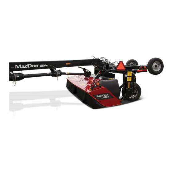
Rotary disc header
Hide thumbs
Also See for R1 Series:
- Operator's manual (368 pages) ,
- Installation instructions manual (48 pages) ,
- Quick start manual (2 pages)

Related Manuals for MacDon R1 Series


Summary of Contents for MacDon R1 Series
- Page 1 R1 Series Rotary Disc Header Operator s Manual 215622 Revision A Original Instruction The Harvesting Specialists.
- Page 2 © 2021 MacDon Industries, Ltd. The information in this publication is based on the information available and in effect at the time of printing. MacDon Industries, Ltd. makes no representation or warranty of any kind, whether expressed or implied, with respect to the information in this publication.
- Page 3 Declaration of Conformity 215622 Revision A...
- Page 4 215622 Revision A...
- Page 5 This instructional manual contains safety, operating, and maintenance procedures for the MacDon R113 and R116 Rotary Disc Headers. The rotary disc header, when attached to a MacDon Windrower, is designed to cut, condition, and lay a wide variety of grasses and hay crops in windrows. The following is a list of windrowers which are compatible with the rotary...
- Page 6 Store the operator s manual and the parts catalog in the plastic manual case (A) at the right side of the rotary disc header. NOTE: Keep your MacDon publications up-to-date. The most current version can be downloaded from our website www.
-
Page 7: Summary Of Changes
Summary of Changes At MacDon, we re continuously making improvements. Occasionally, these improvements impact product documentation. The following list provides an account of major changes from the previous version of this document. Internal Use Summary of Change Only Section Updated text of signs MD #184371, 184385, 194466, and 1.9 Understanding Safety Signs, page 11... -
Page 8: Model And Serial Number
Model and Serial Number Record the model number, serial number, and model year of the header on the lines below. Rotary Disc Header Model: Serial Number: Model Year: The serial number plate (A) is located near the base of the right side hazard/signal light on the right edge of the rotary disc header. -
Page 9: Table Of Contents
TABLE OF CONTENTS Declaration of Conformity ..........................i Introduction .............................. iii Summary of Changes............................ v Model and Serial Number ..........................vi Chapter 1: Safety ............................1 1.1 Safety Alert Symbols ..........................1 1.2 Signal Words ............................2 1.3 General Safety ............................3 1.4 Maintenance Safety ..........................5 1.5 Hydraulic Safety .............................6 1.6 Welding Precaution ..........................7 1.7 Safety Signs ............................8... - Page 10 TABLE OF CONTENTS Disconnecting Header Hydraulics M205 Self-Propelled Windrower without Quick Couplers....76 Disconnecting Header Electrical System M205 Self-Propelled Windrower........... 77 3.6 Driveshields............................80 3.6.1 Opening Driveshields ........................80 3.6.2 Closing Driveshields........................81 3.7 Cutterbar Doors ........................... 83 3.7.1 Opening Cutterbar Doors North America ..................83 3.7.2 Opening Cutterbar Doors Export Latches ..................
- Page 11 TABLE OF CONTENTS Chapter 4: Maintenance and Servicing....................111 4.1 Preparing Machine for Servicing......................111 4.2 Recommended Safety Procedures ......................112 4.3 Maintenance Requirements ......................... 114 4.3.1 Maintenance Schedule/Record ..................... 114 4.3.2 Break-In Inspections ........................117 4.3.3 Preseason Servicing........................117 4.3.4 End-of-Season Servicing ......................
- Page 12 TABLE OF CONTENTS Removing Large Driven Drums and Driveline R113 or R116 SP............173 Installing Large Driven Drums and Driveline R113 or R116 SP ............176 Removing Large Non-Driven Drums R113 or R116 SP..............180 Installing Large Non-Driven Drums R113 or R116 SP ..............182 4.5.9 Replacing Cutterbar Spindle Shear Pin ...................
- Page 13 TABLE OF CONTENTS 5.1.1 Tall Crop Divider Kit........................235 5.1.2 No Conditioner Kit ........................235 5.1.3 Polyurethane Roll Conditioner Kit ....................235 5.1.4 Steel Roll Conditioner Kit......................235 5.2 Hydraulic Drive Conversion Kits......................236 5.2.1 R1 to M1170 Hydraulic Drive Kit ....................236 5.2.2 M1240 Case Drain Kit .........................
-
Page 15: Chapter 1: Safety
Chapter 1: Safety Understanding and consistently following these safety procedures will help to ensure the safety of those operating the machine and of bystanders. 1.1 Safety Alert Symbols The safety alert symbol indicates important safety messages in this manual and on safety signs on the machine. This symbol means: ATTENTION! BECOME ALERT! -
Page 16: Signal Words
SAFETY 1.2 Signal Words Three signal words, DANGER, WARNING, and CAUTION, are used to alert you to hazardous situations. Two signal words, IMPORTANT and NOTE, identify non-safety related information. Signal words are selected using the following guidelines: DANGER Indicates an imminently hazardous situation that, if not avoided, will result in death or serious injury. WARNING Indicates a potentially hazardous situation that, if not avoided, could result in death or serious injury. -
Page 17: General Safety
SAFETY 1.3 General Safety Protect yourself when assembling, operating, and servicing machinery. CAUTION The following general farm safety precautions should be part of your operating procedure for all types of machinery. Wear all protective clothing and personal safety devices that could be necessary for the job at hand. - Page 18 SAFETY Wear close-fitting clothing and cover long hair. NEVER wear dangling items such as scarves or bracelets. Keep all shields in place. NEVER alter or remove safety equipment. Ensure that the driveline guards can rotate independently of their shaft, and that they can telescope freely.
-
Page 19: Maintenance Safety
SAFETY 1.4 Maintenance Safety Protect yourself when servicing machinery. To ensure your safety while maintaining the machine: Review the operator s manual and all safety items before the operation and/or maintenance of the machine. Place all controls in Neutral, stop the engine, set the parking brake, remove the ignition key, and wait for all moving parts to stop before servicing, adjusting, and/or repairing the machine. -
Page 20: Hydraulic Safety
SAFETY 1.5 Hydraulic Safety Protect yourself when assembling, operating, and servicing hydraulic components. Always place all hydraulic controls in Neutral before leaving the operator s seat. Make sure that all components in the hydraulic system are kept clean and in good condition. Replace any worn, cut, abraded, flattened, or crimped hoses and steel lines. -
Page 21: Welding Precaution
It is very important that welding on the header is not attempted while the header is connected to the windrower. If it is unfeasible to disconnect the rotary disc header from the windrower before welding, contact your MacDon Dealer for welding precautions detailing all electrical components that must be disconnected first for safe welding. -
Page 22: Safety Signs
If the original part on which a safety sign was installed is replaced, ensure that the repair part displays the current safety sign. Replacement safety signs are available from your MacDon Dealer Parts Department. Figure 1.14: Operator’s Manual Decal 1.7.1 Installing Safety Decals If a safety decal is damaged it should be replaced. -
Page 23: Safety Sign Locations
SAFETY 1.8 Safety Sign Locations Safety signs are installed in several locations on the header. Replace any missing or damaged decals on the machine with identical parts. Figure 1.15: Safety Sign Decal Locations – R116 SP Shown, R113 SP Similar A - MD #194466 B - MD #247167 C - MD #194465... - Page 24 SAFETY Figure 1.17: Safety Sign Decal Locations Roll Conditioner A - MD #190546 B - MD #184385 C - MD #184371 D - MD #246959 E - MD #246956 F - NO STEP Symbol (Imprinted on Shield) 215622 Revision A...
-
Page 25: Understanding Safety Signs
SAFETY 1.9 Understanding Safety Signs Understanding these safety signs will allow you to understand the various hazards that your equipment may present. NOTE: This is a general list of safety sign definitions and the decals listed may not necessarily be applicable to your machine. MD #113482 General hazard pertaining to machine operation and servicing. - Page 26 SAFETY MD #184371 Hand entanglement hazard WARNING To prevent injury: Stop the engine and remove the key before opening the shield. Do not operate the machine without the shields in place. Figure 1.20: MD #184371 MD #184385 Entanglement hazard DANGER To prevent injury from entanglement with the conditioner: Stand clear of the machine while it is running.
- Page 27 SAFETY MD #194465 Rotating cutters WARNING – STAND CLEAR Contact with the cutter blades, or objects thrown by the rotating blades, can result in serious injury or death. Do NOT stand on or near the machine when it is in operation. Do NOT operate the machine with the covers or curtains open or removed.
- Page 28 SAFETY MD #246959 Pinch hazard WARNING – KEEP AWAY Failure to comply could result in death or serious injury. Figure 1.26: MD #246959 MD #247167 Rotating blades WARNING Disengage the power take-off, shut off the engine, and remove the key before opening the covers. Ensure that the blades have stopped rotating before lifting the cover.
-
Page 29: Chapter 2: Product Overview
Weight: base machine, adapter frame, and steel conditioner 1850 kg (4079 lb.) 1982 kg (4369 lb.) Weight: base machine, adapter frame, and polyurethane 1868 kg (4118 lb.) 1999 kg (4408 lb.) conditioner MacDon M155, MacDon M155, M155E4, M205, M155E4, or M1170 Compatible windrowers M1170, or M1240 Windrower... - Page 30 PRODUCT OVERVIEW R113 SP R116 SP Hay Conditioner Options Optional Steel rolls Roll type Steel on steel chevron conditioner rolls Roll length 3275 mm (129 in.) 229 mm (9.0 in.) / 179 mm (7.0 in.) OD tube Roll diameter Roll speed 1009 rpm Polyurethane rolls Optional...
-
Page 31: Component Identification
PRODUCT OVERVIEW 2.2 Component Identification Operating and maintaining the header requires understanding the names of its parts and their locations. Figure 2.1: R1 SP Series – R113 SP Shown, R116 SP Similar A - Front Curtains B - Cutterbar Doors C - Drive Shield (Left) D - Hose Support 2 E - Hydraulic Motor 3... - Page 32 PRODUCT OVERVIEW Figure 2.2: R1 SP Series – R113 SP Shown, R116 SP Similar A - Header Supports B - Side Deflectors C - Side Deflector Adjuster Handles D - Rear Crop Baffle E - Adapter Frame F - Drive Shield 215622 Revision A...
-
Page 33: Definitions
Horsepower Joint Industrial Council: A standards body that developed standard sizing and shape for original 37° flared fitting MacDon M100, M105, M150, M155, M155E4, M200, and M205 Windrowers M Series Windrowers M1 Series Windrowers MacDon M1170 and M1240 Windrowers... - Page 34 PRODUCT OVERVIEW Term Definition A tightening procedure where fitting is assembled to a precondition (finger tight) and Torque angle then nut is turned farther a number of degrees to achieve its final position The relationship between assembly torque applied to a piece of hardware and axial load Torque-tension it induces in bolt or screw A thin cylinder with a hole or slot located in the center that is to be used as a spacer, load...
-
Page 35: Chapter 3: Operation
Chapter 3: Operation Safely operating your machine requires familiarizing yourself with its capabilities. 3.1 Break-In Period A brand-new machine must be operated gently when it is run for the first time. After attaching the header to the windrower for the first time, operate the machine slowly for five minutes, watching and listening from the operator s seat for binding or interfering parts. -
Page 36: Daily Start-Up Check
OPERATION 3.2 Daily Start-Up Check Perform this procedure before operating the machine. CAUTION • Ensure that the windrower and the header are properly attached, all controls are in neutral, and the windrower brakes are engaged. • Clear the area of bystanders, pets, etc. Keep children away from the machinery. Walk around the header confirm that no one is under, on, or close to it. -
Page 37: Engaging And Disengaging Header Safety Props
OPERATION 3.3 Engaging and Disengaging Header Safety Props Safety props are located on both header lift cylinders on the windrower. Refer to the relevant procedure for your windrower: 3.3.1 Engaging and Disengaging Header Safety Props – M1 Series Windrower, page For M1 Series Windrowers, refer to 3.3.2 Engaging and Disengaging Header Safety Props –... -
Page 38: Engaging And Disengaging Header Safety Props M155, M155E4, Or M205 Self-Propelled
OPERATION 5. Disengage the safety props on both lift cylinders as follows: Turn lever (A) away from the header to raise the safety prop until the lever locks into the vertical position. b. Repeat the previous step for the opposite cylinder. NOTE: If the safety prop will NOT disengage, raise the header to release the prop. - Page 39 OPERATION 3. Engage the safety props on both lift cylinders as follows: Pull lever (A) and rotate it toward the header to lower safety prop (B) onto the cylinder. b. Repeat the previous step for the opposite lift cylinder. Figure 3.5: Safety Prop DANGER To avoid bodily injury or death from unexpected startup of the machine, always stop the engine and remove the key from the ignition before leaving the operator’s seat for any reason.
-
Page 40: Attaching Rotary Disc Header To Windrower
OPERATION 3.4 Attaching Rotary Disc Header to Windrower The procedure for attaching a rotary disc header to a windrower varies depending on the windrower model and how that windrower is equipped. Proceed to the header attaching procedure that is suitable for your windrower: 3.4.1 Attaching Header to M1 Series Windrower, page 26 3.4.2 Attaching Header to M155, M155E4, or M205 Windrower –... - Page 41 OPERATION 4. Remove hairpin (A) from clevis pin (B), and remove the pin from header support (C) on both sides of the header. DANGER Check to be sure all bystanders have cleared the area. 5. Start the windrower engine. For instructions, refer to the windrower operator s manual.
- Page 42 OPERATION 9. Press soft key 3 (A) to remove the header float. NOTE: If the header float is active, the icon at soft key 3 will display Remove Float; if the header float has been removed, then the icon will display Resume Float. Figure 3.12: HPT Display 10.
- Page 43 OPERATION 14. Windrowers equipped with the self-aligning center-link kit: Adjust the position of center-link cylinder (A) with the switches on the GSL until hook (B) is above the header attachment pin. IMPORTANT: Hook release (C) must be down to enable the self- locking mechanism.
- Page 44 OPERATION 16. Press HEADER UP switch (A) to raise the header to its maximum height. NOTE: If one end of the header does NOT fully raise, rephase the lift cylinders as follows: Press and hold HEADER UP switch (A) until both cylinders stop moving.
- Page 45 OPERATION 20. Disengage the safety props on both lift cylinders as follows: Turn lever (A) away from the header to raise the safety prop until the lever locks into the vertical position. b. Repeat the previous step for the opposite cylinder. NOTE: If the safety prop will NOT disengage, raise the header to release the prop.
-
Page 46: Attaching Header To M155, M155E4, Or M205 Windrower Hydraulic Center-Link With Optional Self-Alignment
OPERATION 3.4.2 Attaching Header to M155, M155E4, or M205 Windrower – Hydraulic Center-Link with Optional Self-Alignment The procedure for attaching the header to an M Series Windrower varies depending on whether or not the self-aligning center-link is installed. DANGER To avoid bodily injury or death from unexpected startup of the machine, always stop the engine and remove the key from the ignition before leaving the operator’s seat for any reason. - Page 47 OPERATION 4. Remove the float engagement pin from hole (A) to disengage the float springs, and insert the float engagement pin into storage hole (B). Secure the pin with the lynch pin. Repeat this step for the opposite linkage. IMPORTANT: To prevent damage to the lift system when lowering the header lift linkages without a header or a weight box attached to the windrower, ensure that the float...
- Page 48 OPERATION 7. Slowly drive the windrower forward until windrower feet (A) enter header supports (B). Continue driving slowly forward until the feet engage the supports and the header is nudged forward. Figure 3.27: Header Support 8. Use the following GSL functions to position the center-link hook above the header attachment pin: REEL UP (A) to raise the center-link REEL DOWN (B) to lower the center-link...
- Page 49 OPERATION 12. Press HEADER UP switch (A) to raise the header to maximum height. 13. If one end of the header does NOT fully raise, rephase the lift cylinders as follows: Press and hold the HEADER UP switch until both cylinders stop moving.
- Page 50 OPERATION 15. Install clevis pin (A) through the support and the windrower lift member, and secure it with hairpin (B). Repeat this step for the opposite side of the machine. IMPORTANT: Ensure that clevis pin (A) is fully inserted and that the hairpin is installed behind the bracket.
-
Page 51: Attaching Header To M155, M155E4, M205 Windrower Hydraulic Center-Link Without Optional Self-Alignment
OPERATION DANGER Check to be sure all bystanders have cleared the area. 19. Start the engine, and press HEADER DOWN switch (A) on the GSL to fully lower the header. 20. Stop the engine, and remove the key from the ignition. Figure 3.35: Ground Speed Lever 3.4.3 Attaching Header to M155, M155E4, M205 Windrower –... - Page 52 OPERATION 3. Remove hairpin (B) from clevis pin (A), and then remove the clevis pin from header support (C) on both sides of the header. Figure 3.37: Header Support 4. To disengage the float springs, move the float engagement pin from engaged position (A) and insert the pin into storage hole (B).
- Page 53 OPERATION 6. Remove pin (A) from the frame linkage and raise center- link (B) until the hook is above the attachment pin on the header. Replace pin (A) to hold the center-link in place. IMPORTANT: If the center-link is too low, it may contact the header as the windrower approaches the header for hookup.
- Page 54 OPERATION 10. Push down on the rod end of link cylinder (A) until hook (B) engages and locks onto the header pin. IMPORTANT: The hook release must be down to enable the self-locking mechanism. If the release is open (up), manually push it down after the hook engages the header pin.
- Page 55 OPERATION 15. Engage the safety props on both lift cylinders: Shut down the engine, and remove the key from the ignition. b. Pull lever (A) and rotate it towards the header to release and lower safety prop (B) onto the lift cylinder. Repeat the previous steps for the opposite lift cylinder.
- Page 56 OPERATION 17. Remove the clevis pin from storage position (B) in the linkage and insert it into hole (A) to engage the float springs. Secure it with the hairpin. Figure 3.47: Header Float Linkage 18. Disengage the safety prop by turning lever (A) downwards until the lever locks into vertical position.
-
Page 57: Attaching Hydraulic And Electrical Components
Hydraulic conversion kits are needed to convert a header configured for operating with an M1 Series Windrower so that it can work with an M Series windrower, and vice versa. Contact your MacDon Dealer for more information. Refer to the relevant hydraulic and electrical attachment procedure: Connecting Header Hydraulics and Electrical Components –... - Page 58 OPERATION 1. Move the windrower s left platform to the OPEN position. Refer to your windrower operator s manual for instructions. 2. Retrieve the hydraulic hoses from the header. Figure 3.52: Windrower Left Platform Open – M1240 Shown 3. Attach hose support (A) to the windrower frame near the left leg, and route the hose bundle under the frame.
- Page 59 OPERATION 4. Rest the hose bundle routed from the windrower on header hose support (A). 5. If necessary, use a clean rag to remove any dirt and moisture from the couplers. Figure 3.54: Hose Support 6. Connect the header hydraulic hoses and electrical harness as follows: Connect the pressure hose to receptacle (A).
- Page 60 OPERATION 7. M1170 Windrowers: Connect the hydraulic hoses and the electrical harness to receptacles on the windrower as follows: Connect the pressure hose to receptacle (A). b. Connect the return hose to receptacle (B). Connect the case drain hose to receptacle (C). d.
- Page 61 OPERATION 8. M1240 Windrowers: Connect the hydraulic hoses and electrical harness to the receptacles on the windrower. Refer to the illustration which describes the configuration of your windrower. Connect the pressure hose to receptacle (A). b. Connect the return hose to receptacle (B). Connect the case drain hose non-flat face coupler to receptacle (C).
-
Page 62: Connecting Header Hydraulic And Electrical Components M155 Or M155E4 Windrower
Ensure that the hydraulic hoses and electrical harness are routed so that they do not interfere with any moving parts, and so that they are not damaged by rubbing. NOTE: Hydraulic drive kit (A) (MD #B6272) is required for an R1 Series Rotary Disc Header to operate correctly on M155 and M155E4 Self-Propelled Windrowers. To order this kit, contact your MacDon Dealer. - Page 63 OPERATION 3. Move hose bundle (A) from the windrower and rest the bundle on the header. Figure 3.61: Hose Bundle 4. Position the hose support so that lower bolt (A) is in the forward hole as shown. Loosen both bolts and adjust them as required.
- Page 64 OPERATION 5. Move the windrower s left platform (A) to the OPEN position. Refer to your windrower operator s manual for instructions. Figure 3.63: Windrower Left Platform in Open Position 6. Route windrower hose bundle (A) through hose support (B) on the header.
- Page 65 OPERATION 8. Connect pressure hose (A) routed from the header to the hydraulic coupler at port M2 (B) on the windrower s auxiliary disc drive manifold (the middle valve block). Figure 3.65: Hydraulic Connections 9. Remove the caps and plugs from the hoses on the windrower and from the lines on the header.
- Page 66 OPERATION 11. Connect return hose (A) from port R1 (C) on the windrower s drive manifold to the coupler on steel line (B) attached to the aft port on the header motor. Figure 3.67: Hydraulic Connections NOTE: If the windrower is equipped with reverser manifold (A) for an auger header, route return hose (B) from port R1 (D) on the windrower s reverser manifold to steel line (C) attached to the aft port on the header motor.
- Page 67 OPERATION 12. Connect case drain hose (A) from lift manifold port T3 (C) to the 1/2 in. female coupler at the bulkhead, which is attached to motor port (B). Figure 3.69: Hydraulic Connections 13. Connect electrical harness (A) from the windrower to electrical connector (B) on the header.
- Page 68 OPERATION 14. Lower and lock lever (A). 15. Secure hose (B) with three adjustable straps (C). Figure 3.71: Hose Bundle 16. Move platform (A) to the CLOSED position. Figure 3.72: Top View of Windrower 215622 Revision A...
-
Page 69: Connecting Header Hydraulics And Electrical Components M205 Self-Propelled Windrower
OPERATION Connecting Header Hydraulics and Electrical Components – M205 Self-Propelled Windrower Ensure that the hydraulic hoses and electrical harness are routed so that they do not interfere with any moving parts, and so that they are not damaged by rubbing. DANGER To avoid bodily injury or death from unexpected startup of the machine, always stop the engine and remove the key from the ignition before leaving the operator’s seat for any reason. - Page 70 OPERATION NOTE: The pressure hose crosses on top of the return hose once it is routed past support (B). 2. Proceed according to the type of hydraulic couplers or fittings used on the M205: If the M205 is equipped with quick couplers (A) to connect to the header, proceed to Connecting R113 Rotary Disc Header Hydraulics –...
- Page 71 OPERATION Connecting R113 Rotary Disc Header Hydraulics – M205 Self-Propelled Windrower with Quick Couplers Ensure that the couplers are fully mated when connecting the R113 Rotary Disc Header to an M205 Self-Propelled Windrower with hydraulic quick couplers. 1. Locate pressure and return hydraulic hoses (A) on the left side of the header.
- Page 72 OPERATION 4. Connect pressure coupler (A) to inboard steel line coupler (B). NOTE: For reference, the other end of the pressure hose is connected to split flange clamp (C) on the hydraulic motor. 5. Connect return coupler (D) to outboard steel line coupler (E).
- Page 73 OPERATION 8. Connect case drain hose (A) to 1/2 in. male flat face fitting (B). 9. Secure the case drain hose to the coupler lock assembly with two clamps (C). 10. Open the left driveshield. For instructions, refer to 3.6.1 Opening Driveshields, page Figure 3.82: Case Drain Connection 11.
- Page 74 OPERATION 2. Install union fitting (A) onto header pressure hose (B). 3. Install union fitting (C) onto header return hose (D). Figure 3.85: Header Hoses and Union Fittings 4. Connect the PRESSURE hose with union fitting (A) to inboard steel line (B) on the left side of the windrower. NOTE: For reference, the other end of the pressure hose is connected to split flange clamp (C) on the hydraulic motor.
- Page 75 OPERATION 8. Ensure that the speed sensor is installed correctly for the windrower; use top hole (A) for the M205 Windrower. 9. Close the left endshield. For instructions, refer to 3.6.2 Closing Driveshields, page Figure 3.87: Speed Sensor Connecting R113 Rotary Disc Header Electrical Components – M205 Self-Propelled Windrower The adapter harness and the power limiter harness on the R113 must be connected to the M205 s electrical system.
- Page 76 OPERATION 3. Disconnect 4-pin female piston pump connector (A) from header pump relay harness (B). Figure 3.89: Piston Pump 215622 Revision A...
- Page 77 OPERATION Figure 3.90: Power Limiter Harness Installation 4. Connect the power limiter harness (MD #256651) as follows: Connect 4-pin male connector (A) to piston pump (B). Connect 4-pin female connector (C) to header pump relay harness (D). Route the power wire with terminal (F) through frame channel hole (E) and connect it to bus bar stud (G) beside the battery.
- Page 78 OPERATION 5. Confirm that the power limiter harness is functional by checking the red LED light on module (A): If the light is solid, then the harness is functioning correctly. If the light is flashing, then the connection is incorrect. These are the possible causes of an incomplete connection: The power supply might be reversed.
-
Page 79: Detaching Header From Windrower
Detach the header when replacing the header with a different one or when storing the header. 3.5.1 Detaching Header from M1 Series Windrower Detaching an R1 Series header from an M1 Series windrower requires removing the electrical and hydraulic connections, detaching the header supports, and releasing the center link. - Page 80 OPERATION 5. Open the left platform on the windrower. For instructions, refer to the windrower operator s manual. Figure 3.94: Left Platform Open – M1240 Windrower 6. Disconnect electrical harness (A) and hydraulic hoses (B), (C), and (D) from the windrower. Figure 3.95: Header Drive Hydraulics 215622 Revision A...
- Page 81 OPERATION 7. Remove hose support (A) and the hose bundle from the windrower frame. Figure 3.96: Hoses on Windrower 8. Slide support (A) into center-link support (B) and secure it with hardware (C). Figure 3.97: Hose Storage Position 215622 Revision A...
- Page 82 OPERATION 9. Store hoses (A) and electrical harness (B) disconnected from the windrower in Step 6, page 66 into storage plate (C). NOTE: Install caps and plugs on open lines to prevent the buildup of dirt and debris while the header is in storage. NOTE: Some parts have been removed from the illustration for the sake of clarity.
- Page 83 OPERATION 11. Windrowers WITH center-link self-alignment kit: Release center-link latch (A). Figure 3.100: Center-Link 12. Disengage the safety props on both lift cylinders as follows: Turn lever (A) away from the header to raise the safety prop until the lever locks into the vertical position. b.
-
Page 84: Detaching Header From M155 Or M155E4 Self-Propelled Windrower
3.5.2 Detaching Header from M155 or M155E4 Self-Propelled Windrower Detaching an R1 Series Rotary Disc Header from an M155 or M155E4 Self-Propelled Windrower involves removing the electrical and hydraulic connections and then following the detaching procedure in the windrower operator s manual. - Page 85 OPERATION 3. Move left platform (A) to the open position. Figure 3.105: Windrower Left Side Platform 4. Disconnect hose (A) from port M2 on the disc drive valve. Figure 3.106: Hydraulic Connections 215622 Revision A...
- Page 86 OPERATION 5. Raise lever (A) and undo three cinch straps (C). 6. Move hose (B) so that it can be stored on the header. Figure 3.107: Hose Bundle 7. Disconnect the following hoses from the hydraulic motor: Pressure hose (A) Return hose (B) Case drain hose (C) 8.
- Page 87 OPERATION 9. Disconnect electrical connector (A) by turning the collar counterclockwise and pulling on the connector. NOTE: The hydraulic lines and hoses in the illustration have been hidden in order to show the electrical connection. Figure 3.109: Electrical Connection 10. Move the hose bundle from the header to left hose support (B).
-
Page 88: Detaching Header From M205 Windrower
OPERATION 13. Move windrower platform (A) to the CLOSED position. 14. Refer to the windrower operator s manual for instructions on how to mechanically detach the header from the windrower. Figure 3.111: M155 Windrower 3.5.3 Detaching Header from M205 Windrower The procedure for detaching your R113 SP Rotary Disc Header from an M205 Windrower will depend on whether or not the windrower is equipped with hydraulic quick couplers. -
Page 89: Disconnecting Header Hydraulics M205 Self-Propelled Windrower With Quick Couplers
OPERATION 3. Move left platform (A) to the open position. 4. To disconnect an R113 SP from an M205 Windrower equipped with quick couplers, refer to Disconnecting Header Hydraulics – M205 Self-Propelled Windrower with Quick Couplers, page 5. To disconnect an R113 SP from an M205 Windrower not equipped with quick couplers, refer to Disconnecting Header Hydraulics –... -
Page 90: Disconnecting Header Hydraulics M205 Self-Propelled Windrower Without Quick Couplers
OPERATION 3. Disconnect PRESSURE coupler (A) from inboard steel line coupler (B). 4. Disconnect RETURN coupler (C) from outboard steel line coupler (D). 5. Remove pin (E) and open coupler lock assembly (F) over the couplers. 6. Disconnect the electrical connectors. For instructions, refer Disconnecting Header Electrical System –... -
Page 91: Disconnecting Header Electrical System M205 Self-Propelled Windrower
OPERATION Disconnecting Header Electrical System – M205 Self-Propelled Windrower The procedure for disconnecting an R113 Rotary Disc Header from an M205 Self-Propelled Windrower differs depending on whether or not you are simply swapping the header or storing it long-term. IMPORTANT: Ensure that module (E) is disconnected at header pump relay harness (D) when operating with any other header. - Page 92 OPERATION 3. Disconnect the adapter harness: Disconnect 8-pin female connector (B) from chassis harness connector HC-2 (A). Disconnect 29-pin round male connector (C) from R113 SP header connector (D). 4. Proceed to Step 6, page Figure 3.118: M205 Adapter Harness 5.
- Page 93 OPERATION Figure 3.120: Detaching Header Hose from Windrower 6. Remove hose support pin (B) from hole (C) in the windrower frame. 7. Place header hose bundle (A) on top of the rotary disc header. 215622 Revision A...
-
Page 94: Driveshields
OPERATION 3.6 Driveshields Driveshields protect people from rotating belts and drives. The header has two driveshields: one on the left side, and one on the right side. 3.6.1 Opening Driveshields The driveshields protect sensitive components from damage. Open them only when you intend to service the header. WARNING To reduce the risk of personal injury, do NOT operate the machine without the driveshields in place and secured. -
Page 95: Closing Driveshields
OPERATION 3. Insert the flat end of tool (A) into latch (B) and turn it counterclockwise to unlock the driveshield. Figure 3.123: Driveshield Latch 4. Pull the top of driveshield (A) away from the header to open it. NOTE: For improved access, lift the driveshield off of the pins at the base of the shield, and lay the shield on the header. - Page 96 OPERATION 1. Position the driveshield the onto pins, if necessary. 2. Push driveshield (A) to engage latch (B). 3. Ensure that the driveshield is properly secured. Figure 3.125: Left Driveshield 4. Replace tool (B) and lynch pin (A) onto pin (C). Figure 3.126: Left Driveshield 215622 Revision A...
-
Page 97: Cutterbar Doors
OPERATION 3.7 Cutterbar Doors Two doors with rubber curtains provide access to the cutterbar area. WARNING To reduce the risk of personal injury and machine damage, do NOT operate the machine without all the cutterbar doors down or without curtains installed and in good condition. Objects in the path of the blades can be ejected with considerable force when the machine is started. -
Page 98: Opening Cutterbar Doors Export Latches
OPERATION 2. Lift up doors (A) at the front of the machine. Figure 3.128: Cutterbar Doors and Curtains – R113 SP Shown, R116 SP Similar 3.7.2 Opening Cutterbar Doors – Export Latches Machines sold outside North America have a tool-operated latch on the cutterbar doors. DANGER To avoid bodily injury or death from unexpected startup of the machine, always stop the engine and remove the key from the ignition before leaving the operator’s seat for any reason. -
Page 99: Closing Cutterbar Doors
OPERATION 3. Use a rod or screwdriver to press down on latch (A) to release the cutterbar door. Figure 3.130: Cutterbar Door Latch – Cutaway View 4. Lift up on doors (A) while pressing down on the latch. Figure 3.131: R113 SP Cutterbar Doors Shown, R116 SP Similar 3.7.3 Closing Cutterbar Doors Do not operate the machine without closing the cutterbar doors. - Page 100 OPERATION 1. Pull down on door (A) from the top to close. 2. Ensure that the curtains hang properly and completely enclose the cutterbar area. Figure 3.132: Cutterbar Doors and Curtains 215622 Revision A...
-
Page 101: Header Settings
OPERATION 3.8 Header Settings Satisfactory operation of the rotary disc header in all situations requires making proper adjustments to suit various crops and conditions. Correct operation of the machine reduces crop loss and increases productivity. Proper adjustments and timely maintenance extend the service life of the machine. -
Page 102: Adjusting Cutting Height
OPERATION Adjusting Cutting Height Lowering the skid shoes and decreasing the cutterbar angle increases the cutting height, resulting in taller stubble that helps material dry faster. Raising the skid shoes and increasing the cutterbar angle decreases the cutting height, resulting in shorter stubble. -
Page 103: Cutterbar Angle
OPERATION Figure 3.134: Skid Shoes – R116 SP 3.8.2 Cutterbar Angle Cutterbar angle (sometimes called header angle) is the angle at which the cutterbar approaches the crop relative to the ground. It is one of the variables which impact cutting height and quality. The cutterbar angle (A) adjustment ranges from 0°... -
Page 104: Header Float
OPERATION 3.8.3 Header Float The header float feature allows the header to closely follow the contours of the ground and respond quickly to changes in elevation or obstacles. The ideal float setting is the one where the cutterbar is on the ground and is able to cut with minimal header bouncing, and without scooping or pushing soil. - Page 105 OPERATION Figure 3.136: Ground Speed for R113 and R116 Rotary Disc Headers A - Acres/Hour B - Hectares/Hour C - Kilometers/Hour D - Miles/Hour E - R116 SP F - R113 SP 215622 Revision A...
-
Page 106: Reconfiguring Cutterbar Crop Stream
OPERATION 3.9 Reconfiguring Cutterbar Crop Stream Discs are factory-installed to produce three crop streams. However, the disc rotation pattern can be changed by changing the spindle and its disc to suit crop conditions. Each spindle and disc pair is designed to rotate in one direction, and must be changed as a set when the crop flow is altered. -
Page 107: Changing Header Cutterbar Crop Stream Configuration
OPERATION 3.9.1 Changing Header Cutterbar Crop Stream Configuration Two crop stream settings are possible: one stream and three streams. Figure 3.139: R113 SP (8 Disc) Spindle Rotation Pattern and Crop Streams A - One Crop Stream B - Three Crop Streams To change R113 SP (8 disc) spindle rotation from three crop streams (B) to one crop stream (A): Swap disc/spindle (3) with disc/spindle (6) To change R113 SP (8 disc) spindle rotation from one crop stream (A) to three crop streams (B):... -
Page 108: Changing Header Cutterbar Crop Stream Configuration
OPERATION 3.9.2 Changing Header Cutterbar Crop Stream Configuration Two crop stream settings are possible: one stream and three streams. Figure 3.140: R116 SP (10 Disc) Spindle Rotation Pattern and Crop Streams A - One Crop Stream B - Three Crop Streams To change R116 SP (10 disc) spindle rotation from one crop stream (A) to three crop streams (B): Swap disc/spindle (7) with disc/spindle (4). -
Page 109: Conditioner
OPERATION 3.10 Conditioner Conditioner rolls condition the crop by crimping and crushing the stem in several places, which allows the release of moisture, resulting in faster crop drying times. Both steel and polyurethane conditioner rolls are available. Refer to 5 Options and Attachments, page 235 for information on ordering conditioner rolls. -
Page 110: Adjusting Roll Gap Polyurethane Rolls
OPERATION 3. Polyurethane rolls: Insert a feeler gauge through the inspection hole in the conditioner endsheet to check the roll gap on polyurethane roll conditioners. The factory setting is 3 mm (1/8 in.). Figure 3.141: Polyurethane Roll Conditioner 4. Steel rolls: The length of thread (A) extending above the jam nut on the adjustment rods can be used as an approximation of the roll gap. -
Page 111: Adjusting Roll Gap Steel Rolls
OPERATION 3. Loosen upper jam nut (A) on both sides of the conditioner attachment. 4. Turn lower nut (B) counterclockwise until the upper roll rests on the lower roll. 5. Turn lower nut (B) one full turn clockwise to raise the upper roll and achieve a 3 mm (1/8 in.) roll gap. -
Page 112: Roll Tension
OPERATION NOTE: Make further adjustments to the roll gap based on cutting performance and crop conditions. 3.10.2 Roll Tension Roll tension refers to the tension holding the rolls together. It is factory-set to maximum and should rarely require adjustment. Heavy crops or tough forage can, however, cause the rolls to separate. In such conditions, maximum roll tension is required to ensure that the cut crop is crimped sufficiently. -
Page 113: Roll Timing
OPERATION 3.10.3 Roll Timing For proper conditioning, the rolls must be properly timed, so that the bar on one roll is centered between two bars on the other roll. The factory setting should be suitable for most crop conditions. IMPORTANT: Roll timing is critical when the roll gap is decreased because conditioning is affected and the bars may contact each other. - Page 114 OPERATION 3. Secure bottom roll (A). 4. Manually rotate upper roll (B) in a counterclockwise direction until it stops. 5. Make a mark (C) across yoke (D) and gearbox flange (E). Figure 3.148: Conditioner Drive 6. Secure bottom roll (A). 7.
-
Page 115: Forming Shields Roll Conditioner
OPERATION 9. Determine center point (A) between the two marks on the yoke plate, and place a third mark. 10. Rotate upper roll (B) counterclockwise until the mark on the gearbox flange lines up with the third (center) mark. Figure 3.150: Conditioner Drive 11. -
Page 116: Positioning Forming Shield Side Deflectors Roll Conditioner
OPERATION A wider windrow will generally dry faster and more evenly, resulting in less protein loss. Fast drying is especially important in areas where the weather allows only a few days to cut and bale. A narrower windrow may be preferable for ease of pick-up and when drying is not critical (for example, when cutting for silage or green feed). - Page 117 OPERATION 2. Remove lynch pin (A), securing rear baffle adjustment lever (B) to bracket (C). 3. Pull rear baffle adjustment lever (B) inboard to disengage it from bracket (C). 4. Position rear baffle adjustment lever (B) as follows: Move the lever forward to raise the baffle Move the lever backward to lower the baffle 5.
- Page 118 OPERATION 2. Position deflector fin (A) under the baffle and secure it with existing bolt and nut (B). Install the bolt so that the bolt head faces down. Adjust the fin to an angle of approximately 60° as shown, and torque the nut to 69 Nm (51 lbf·ft).
-
Page 119: Cutterbar Deflectors
OPERATION 3.11 Cutterbar Deflectors A two-piece cutterbar deflector is attached to the cutterbar just below the conditioner rolls. Deflectors provide improved feeding into the conditioner rolls and prevent long-stemmed crop from feeding under the rolls. Cutterbar deflectors may not be well-suited for some types of crops and certain field conditions. Refer to the following table: Table 3.2 Conditions for Using Cutterbar Deflectors Use Deflector... -
Page 120: Installing Cutterbar Deflectors R113
OPERATION 3.11.2 Installing Cutterbar Deflectors – R113 When cutting long-stemmed crops in certain field conditions with an R113, installing cutterbar deflectors is recommended. DANGER To avoid bodily injury or death from unexpected start-up or fall of a raised machine, stop the engine, remove the key, and engage the windrower lift cylinder safety props before going under the machine for any reason. -
Page 121: Installing Cutterbar Deflectors R116
OPERATION 4. Locate deflector (A) behind the cutterbar. 5. Clean debris from the deflector area. 6. Remove and retain bolt (B) securing the outboard end of the deflector to the cutterbar.. 7. On the left side of the cutterbar, remove and retain three bolts (C). -
Page 122: Haying Tips
OPERATION 3.12 Haying Tips Follow the recommendations in this section to ensure the highest quality hay production. 3.12.1 Curing Curing crops quickly helps maintain the highest quality of crop material. Approximately 5% of protein is lost from hay for each day that it lays on the ground after cutting. Leaving the windrow as wide and fluffy as possible results in the quickest curing. -
Page 123: Windrow Characteristics
OPERATION 3.12.4 Windrow Characteristics The shape and density of the windrow is an important factor with respect to how rapidly the hay cures. For instructions, refer to 3 Operation, page 21 for instructions on adjusting the header. Table 3.4 Recommended Windrow Characteristics Advantage Characteristic Enables airflow through windrow, which is more important to the curing... -
Page 124: Transporting Header
OPERATION 3.13 Transporting Header For information on transporting the header when attached to the windrower, refer to your windrower operator s manual. IMPORTANT: For cab-forward road travel, the M155 and M155E4 windrower must have the lighting and marking bundle installed (MD #B5412). -
Page 125: Chapter 4: Maintenance And Servicing
Chapter 4: Maintenance and Servicing This section provides information about routine servicing for the header. A parts catalog is located in a plastic case at the right end of the header. Log the machine s hours of operation and use the maintenance record provided (refer to 4.3.1 Maintenance Schedule/ Record, page 114) to keep track of maintenance procedures as they are performed. -
Page 126: Recommended Safety Procedures
MAINTENANCE AND SERVICING 4.2 Recommended Safety Procedures These procedures will minimize the chances of injury when maintaining or repairing the machine. Park on a level surface when possible. Follow all recommendations in your windrower operator's manual. Wear close-fitting clothing and cover any long hair. Never wear dangling items such as scarves or bracelets. - Page 127 MAINTENANCE AND SERVICING Be prepared to deal with an accident should it occur. Know where the first aid kits and fire extinguishers are located, and know how to use them. Figure 4.4: Safety Equipment Keep the service area clean and dry. Wet or oily floors are slippery.
-
Page 128: Maintenance Requirements
MAINTENANCE AND SERVICING 4.3 Maintenance Requirements Regular maintenance is the best insurance against early wear and untimely breakdowns. Following the maintenance schedule will increase your machine s service life. Periodic maintenance requirements are organized according to service intervals. IMPORTANT: The recommended intervals are based on typical operating conditions. Service the machine more often if the machine is operated regularly under adverse conditions, e.g. - Page 129 MAINTENANCE AND SERVICING At First 25 Hours Check conditioner drive belt tension. For ü instructions, refer to Inspecting Conditioner Drive Belt, page 210. Check roll timing gearbox lubricant level. For instructions, refer to 4.6.1 Checking ü and Changing Lubricant in Conditioner Roll Timing Gearbox, page 194.
- Page 130 MAINTENANCE AND SERVICING Every 100 Hours or Annually Check conditioner drive belt tension. For ü instructions, refer to Inspecting Conditioner Drive Belt, page 210. Check roll timing gearbox lubricant. For instructions, refer to 4.6.1 Checking and ü Changing Lubricant in Conditioner Roll Timing Gearbox, page 194.
-
Page 131: Break-In Inspections
MAINTENANCE AND SERVICING 4.3.2 Break-In Inspections From the factory the header is ready for normal operation. However, there are several maintenance tasks to complete during the early operating hours of the machine s service life. Table 4.1 Break-In Inspection Schedule Inspection Item Refer to... -
Page 132: End-Of-Season Servicing
MAINTENANCE AND SERVICING 4.3.4 End-of-Season Servicing Perform these procedures when storing the machine at the end of the season. CAUTION Never use gasoline, naphtha, or any volatile material for cleaning purposes. These materials may be toxic and/or flammable. CAUTION Cover the cutterbar to prevent injury from accidental contact with the blades. 1. -
Page 133: Lubrication
MAINTENANCE AND SERVICING 4.4 Lubrication Proper lubrication is essential to ensuring the service life of the machine. WARNING To avoid personal injury, before servicing header or opening drive covers, refer to 4.1 Preparing Machine for Servicing, page 111. Greasing points are marked on the machine by decals showing a grease gun and the grease interval, which is specified in hours of operation. -
Page 134: First 25 Hours
MAINTENANCE AND SERVICING First 25 Hours After the first 25 hours of operation, you will need to check the conditioner drive belt tension and inspect the conditioner roll timing gearbox s lubricant level. To check the conditioner roll timing gearbox oil level, refer to 4.6.1 Checking and Changing Lubricant in Conditioner Roll Timing Gearbox, page 194. -
Page 135: Every 25 Hours
MAINTENANCE AND SERVICING Every 25 Hours After every 25 hours of machine operation, add grease to the idler/tensioner pivot, the roller conditioner bearing, the driveline U-joints, and the driveline slip joints. When adding grease, use high temperature extreme pressure (EP2) performance grease with 1% max molybdenum disulphide (NLGI grade 2) lithium base unless otherwise specified. -
Page 136: First 50 Hours
MAINTENANCE AND SERVICING First 50 Hours After the first 50 hours of machine operation, the conditioner roll timing gearbox s lubricant will need to be changed, the header drive gearbox s lubricant will need to be changed, and the cutterbar lubricant level should be inspected. To change the conditioner roll timing gearbox oil level, refer to 4.6.1 Checking and Changing Lubricant in Conditioner Roll Timing Gearbox, page... -
Page 137: Every 100 Hours Or Annually
MAINTENANCE AND SERVICING Every 100 Hours or Annually After 100 hours of machine operation, or annually (whichever interval occurs first), the conditioner drive belt tension should be checked, the conditioner roll timing gearbox s lubricant level should be checked, the rotary disc header drive gearbox s lubricant level should be checked, and the forming shield pivot tubes should be lubricated. -
Page 138: Every 250 Hours
MAINTENANCE AND SERVICING Every 250 Hours After every 250 hours, or annually (whichever interval occurs first), the conditioner roll gearbox lubricant should be changed, the rotary disc header drive gearbox lubricant should be changed, and the cutterbar lubricant should be changed. Figure 4.11: Every 250 Hours A - Header Drive Gearbox B - Cutterbar... -
Page 139: Cutterbar System
MAINTENANCE AND SERVICING 4.5 Cutterbar System The cutterbar comes in two cutting widths 3.9 m (13 ft.) and 4.9 m (16 ft.). The 3.9 m (13 ft.) holds eight discs and the 4.9 m (16 ft.) holds ten discs that rotate to a maximum of 2500 rpm at full engine speed. Each disc carries two cutting blades. - Page 140 MAINTENANCE AND SERVICING 3.7.1 Opening Cutterbar Doors – North America, page 83 4. Open the cutterbar doors. For instructions, refer to 3.7.2 Opening Cutterbar Doors – Export Latches, page 5. Open cutterbar doors (A). For instructions, refer to 3.7.1 Opening Cutterbar Doors – North America, page Figure 4.13: Cutterbar Doors –...
- Page 141 MAINTENANCE AND SERVICING 10. Clear all bystanders from the area. 11. Start the engine, and raise the header slightly. 12. Lower the header onto blocks, so the left end is slightly higher than the right end. 13. Shut down the engine, and remove the key from the ignition. 14.
-
Page 142: Draining Cutterbar
MAINTENANCE AND SERVICING Draining Cutterbar In order to change the cutterbar lubricant, the cutterbar will first need to be drained. DANGER To avoid injury or death from unexpected start-up of the machine, always stop the engine and remove the key from the ignition before leaving the operator’s seat for any reason. -
Page 143: Adding Lubricant To Cutterbar
MAINTENANCE AND SERVICING Adding Lubricant to Cutterbar This procedure should be used when the cutterbar has been completely drained of oil. Checking and Adding Lubricant – Cutterbar, page If you are checking the oil level or topping it up, refer to 125. -
Page 144: Cutterbar Discs
MAINTENANCE AND SERVICING 12. Remove the block from under the cutterbar. Checking and Adding Lubricant – Cutterbar, page 13. Check the lubricant level. For instructions, refer to 125. 14. Reinstall the right outboard rock guard. For instructions, refer to Installing Outboard Rock Guards, page 157. - Page 145 MAINTENANCE AND SERVICING 1. Inspect the cutterbar disc for any deformity on the side of the disc blades. Dimension (A) must not exceed 48 mm (1 7/8 in.). Replace any damaged discs immediately. IMPORTANT: Cutterbar discs are NOT repairable and must be replaced if damaged.
-
Page 146: Removing Cutterbar Discs
MAINTENANCE AND SERVICING Removing Cutterbar Discs Cutterbar discs may need to be removed for replacement or so they can be swapped to change the type of crop stream. DANGER To avoid bodily injury or death from unexpected start-up or fall of a raised machine, stop the engine, remove the key, and engage the windrower lift cylinder safety props before going under the machine for any reason. -
Page 147: Installing Cutterbar Discs
MAINTENANCE AND SERVICING 7. Remove cutterbar disc cap (A). 8. Remove cutterbar disc (B). Figure 4.26: Cutterbar Disc and Cap Installing Cutterbar Discs Ensure that the blades of the installed disc are perpendicular to those on the adjacent discs. DANGER To avoid bodily injury or death from unexpected start-up or fall of a raised machine, stop the engine, remove the key, and engage the windrower lift cylinder safety props before going under the machine for any reason. - Page 148 MAINTENANCE AND SERVICING 3. Place a pin (or equivalent) in front hole (D) of the rock guard to prevent the disc from rotating while you are tightening the bolts. 4. Position new disc (A) on the spindle so that the blades are perpendicular to those on the adjacent discs.
-
Page 149: Replacing Cutterbar Spindles
MAINTENANCE AND SERVICING 4.5.3 Replacing Cutterbar Spindles Cutterbar spindles allow for the rotation of the cutterbar discs. They have either right or left-handed threads, and are equipped with a shear pin. A shear pin (as shown by [A]) is installed on each disc in order to prevent damage to the cutterbar if the disc collides with an obstacle. -
Page 150: Removing Cutterbar Spindles
MAINTENANCE AND SERVICING Removing Cutterbar Spindles The cutterbar spindles are secured to the cutterbar frame with 11 nuts and washers. DANGER To avoid bodily injury or death from unexpected start-up or fall of a raised machine, stop the engine, remove the key, and engage the windrower lift cylinder safety props before going under the machine for any reason. - Page 151 MAINTENANCE AND SERVICING 7. Remove cutterbar disc cap (A). 8. Remove cutterbar disc (B). IMPORTANT: The blades are oriented to cut in one direction or the other. Therefore, swap the entire disc when swapping spindles. Figure 4.34: Cutterbar Disc and Cap 9.
-
Page 152: Installing Cutterbar Spindles
MAINTENANCE AND SERVICING 11. Remove spindle (A) from the cutterbar. Figure 4.37: Left Spindle Installing Cutterbar Spindles Ensure that the discs are timed correctly when installing the cutterbar spindles, or damage to the cutterbar may result. Figure 4.38: Underside of Cutterbar Spindles IMPORTANT: Right discs (A) and left discs (B) are timed and must be perpendicular to adjacent discs when they are reinstalled. - Page 153 MAINTENANCE AND SERVICING NOTE: Right discs (A) and left discs (B) are slightly offset as shown, depending on which idler gear the spindle is turning: Spindles that rotate clockwise have left-leading threading Spindles that rotate counterclockwise have right-leading threading DANGER To avoid bodily injury or death from unexpected start-up or fall of a raised machine, stop the engine, remove the key, and engage the windrower lift cylinder safety props before going under the machine for any reason.
- Page 154 MAINTENANCE AND SERVICING 6. Insert spindle (A) into the cutterbar. Figure 4.40: Left Spindle 7. Insert studs (A) into the spindle as shown. NOTE: The plugs are factory-installed as shown in position (B), but may loosen over time. Ensure that the studs are inserted into the proper location.
- Page 155 MAINTENANCE AND SERVICING 10. Torque the bolts to 50 Nm (37 lbf·ft), following the tightening pattern shown. NOTE: The hub has been removed from the illustration for the sake of clarity. Figure 4.43: Tightening Pattern 11. Install spacer plate (A). Figure 4.44: Spacer Plate 12.
-
Page 156: Maintaining Disc Blades
MAINTENANCE AND SERVICING 15. Remove the pin (or equivalent) from the front hole of the rock guard. 16. Close cutterbar doors (A). For instructions, refer to 3.7.3 Closing Cutterbar Doors, page Figure 4.46: Cutterbar Doors – R113 SP Shown, R116 SP Similar 4.5.4 Maintaining Disc Blades Each disc has two blades attached at opposite ends that are free to rotate horizontally on a specially designed shoulder bolt. - Page 157 MAINTENANCE AND SERVICING WARNING Damaged or loose disc blades or blade attachment hardware can be ejected during machine operation and may cause personal injury or machine damage. IMPORTANT: Damaged blades cut poorly and may damage the cutterbar. Replace damaged blades immediately. 1.
-
Page 158: Inspecting Disc Blade Hardware
MAINTENANCE AND SERVICING Figure 4.50: Clockwise Disc Rotation Inspecting Disc Blade Hardware Inspect the blade attachment hardware each time the blades are changed. DANGER To avoid bodily injury or death from unexpected startup of the machine, always stop the engine and remove the key from the ignition before leaving the operator’s seat for any reason. - Page 159 MAINTENANCE AND SERVICING 2. When inspecting the blades, check each blade-attachment bolt and replace it if: The bolt has been removed and installed five times Head (A) is worn flush with the bearing surface of the blade Diameter (B) of the bolt neck is 3 mm (1/8 in.) or less The bolt is cracked (C) The bolt is visibly distorted (D) The bolt shows evidence of interference (E) with...
-
Page 160: Removing Disc Blades
MAINTENANCE AND SERVICING 3. Check the nuts holding the disc blades. Replace the nuts if: The nut has been previously installed; nuts are one-time-use items only The nut shows signs of wear (A) such that the nut has lost more than half the original height (B) in one or more areas. -
Page 161: Installing Disc Blades
MAINTENANCE AND SERVICING 5. Rotate disc (A) so blade (B) faces forward and lines up with hole (C) in the rock guard. Figure 4.54: Disc Blade Aligned with Hole in Rock Guard 6. Place a pin (or equivalent) in the front hole of the rock guard to prevent the disc from rotating while you are loosening blade bolts. - Page 162 MAINTENANCE AND SERVICING 2. Place a pin (or equivalent) in the front hole of the rock guard to prevent the disc from rotating while you are tightening the blade bolts. 3. Install new or reversed blade (A) with shoulder bolt (B) onto disc (C).
-
Page 163: Accelerators
MAINTENANCE AND SERVICING 4.5.5 Accelerators Accelerators are mounted on each outboard disc and are designed to quickly move cut material off the disc and into the conditioner. A pair of accelerators (indicated by [A] in the illustration) is installed on each disc which is topped with a drum. Two pairs of accelerators are installed on an R113 SP (one pair on the outboard disc at each end of the cutterbar) and two pairs are installed on an R116 SP (one pair on each of the two outboard... -
Page 164: Removing Accelerators
MAINTENANCE AND SERVICING WARNING Disc blades have two sharp cutting edges that can cause serious injury. Exercise caution and wear gloves when working with blades. 5. Inspect accelerators (A) for damage and wear. Replace accelerators if they are worn to 50% or more of their original height or if they are no longer effectively moving crop. - Page 165 MAINTENANCE AND SERVICING 4. Open cutterbar doors (A). For instructions, refer to 3.7.1 Opening Cutterbar Doors – North America, page Figure 4.62: Cutterbar Doors – R113 SP Shown, R116 SP Similar WARNING Disc blades have two sharp cutting edges that can cause serious injury. Exercise caution and wear gloves when working with blades.
-
Page 166: Installing Accelerators
MAINTENANCE AND SERVICING Installing Accelerators A new pair of accelerators should be installed on a cutterbar disc whenever the old ones are damaged or so worn that they can no longer effectively move crop off the disc and into the conditioner. WARNING Disc blades have two sharp cutting edges that can cause serious injury. -
Page 167: Rock Guards
MAINTENANCE AND SERVICING 4. Torque inside nut (A) to 58 Nm (43 lbf·ft). 5. Torque outside nut (B) (closest to the blade) to 125 Nm (92 lbf·ft). 6. Repeat Steps 1, page 152 5, page 153 to replace the second accelerator. WARNING Ensure the cutterbar is completely clear of foreign objects. -
Page 168: Removing Inboard Rock Guards
MAINTENANCE AND SERVICING 1. Raise the header fully. 2. Shut down the engine, and remove the key from the ignition. 3. Engage the windrower lift cylinder safety props. For instructions, refer to 3.3 Engaging and Disengaging Header Safety Props, page 4. -
Page 169: Installing Inboard Rock Guards
MAINTENANCE AND SERVICING 5. Slide inboard rock guard (A) forward (in the direction of arrow [B]) and remove it. Figure 4.71: Inboard Rock Guards Installing Inboard Rock Guards Ensure that the nuts securing the rock guards are installed on top of the cutterbar when installing an inboard rock guard. DANGER To avoid bodily injury or death from unexpected start-up or fall of a raised machine, stop engine, remove key, and engage lift cylinder lock-out valves before going under machine for any reason. -
Page 170: Removing Outboard Rock Guards
MAINTENANCE AND SERVICING 5. Install two hex head screws, washers, and lock nuts (A). Torque the hardware to 68 Nm (50 lbf·ft). NOTE: Lock nuts (A) must be installed on top of the cutterbar. Figure 4.73: Inboard Rock Guards Removing Outboard Rock Guards The outboard rock guards are secured to the cutterbar with more hardware than the inboard rock guards. -
Page 171: Installing Outboard Rock Guards
MAINTENANCE AND SERVICING 7. Remove bolt and washers (A). 8. Loosen bolt (B). 9. Remove rock guard (C) by sliding it forward. 10. Repeat Step 4, page 156 to Step 9, page 157 at the opposite side of the cutterbar. Figure 4.75: Left Outboard Rock Guard –... - Page 172 MAINTENANCE AND SERVICING 9. Using a rubber mallet, tap rock guard (A) so it is parallel and flush against cutterbar (B). Figure 4.77: Outboard Rock Guard 10. Ensure that rock guards (B) and (C) are parallel to one another. NOTE: A parallel gap (for example, gap [A]) of 5 7 mm (3/16 1/4 in.) between outboard (B) and inboard (C) rock guards is acceptable.
-
Page 173: Maintaining Small Drums R116 Sp
MAINTENANCE AND SERVICING 4.5.7 Maintaining Small Drums – R116 SP Drums deliver cut material from the ends of the cutterbar and help maintain an even crop flow into the conditioner. The small drums are found on an R116 SP header and are attached to the two discs inboard of the large drums. Inboard drums (B) and (C) are approximately 73 mm (2 3/8 in.) smaller in diameter than outboard drums (A). -
Page 174: Removing Small Driven Drum And Driveline R116 Sp
MAINTENANCE AND SERVICING 4. Inspect small drums (B) and (C) for damage and wear. Replace the drums if they are worn at the center to 50% or less of their original thickness. Do NOT repair damaged drums; they must be replaced. 5. - Page 175 MAINTENANCE AND SERVICING 3. Open cutterbar doors (A). For instructions, refer to 3.7.1 Opening Cutterbar Doors – North America, page Figure 4.84: Cutterbar Doors 4. Remove four M10 hex flange head bolts (A) and remove vertical driveshield (B). Figure 4.85: Driveline Shield 5.
- Page 176 MAINTENANCE AND SERVICING 6. Remove four M10 hex flange head bolts (A), top plate (B), and drum top (C). Figure 4.87: Driveline Shield 7. Remove one 20 mm M10 hex flange head bolt (B), two 16 mm M10 hex flange head bolts (C), and vertical shield (A).
- Page 177 MAINTENANCE AND SERVICING 9. Remove four M12 hex flange head bolts and spacers (A) securing driveline assembly (B) to hub drive (C). Figure 4.90: Hub Drive to Driveline Connection 10. Slide driveline (A) downwards, tilt it to the side, and pull the driveline up and out of drum.
-
Page 178: Installing Small Driven Drum And Driveline R116 Sp
MAINTENANCE AND SERVICING Installing Small Driven Drum and Driveline – R116 SP The small driven drum is the second drum from the end on the left side of the cutterbar. DANGER To avoid injury or death from unexpected start-up of the machine, always stop the engine and remove the key from the ignition before leaving the operator’s seat for any reason. - Page 179 MAINTENANCE AND SERVICING 8. Place a bead of medium-strength threadlocker ® (Loctite 243 or equivalent) around the threads of four M12 hex flange head bolts (A). Use the bolts and spacers to secure driveline assembly (B) to hub drive (C). Torque the bolts to 102 Nm (75 lbf·ft).
- Page 180 MAINTENANCE AND SERVICING 11. Position top plate (B) and drum top (C) onto the drum as shown. Apply a bead of medium-strength threadlocker ® (Loctite 243 or equivalent) around the threads of four M10 hex flange head bolts (A). Use the bolts to secure the top plate and the drum top.
- Page 181 MAINTENANCE AND SERVICING 15. Position vertical driveshield (B) as shown at right. Apply a ® bead of medium-strength threadlocker (Loctite 243 or equivalent) around the threads of four M10 hex flange head bolts (A). Use bolts (A) to secure the vertical driveshield.
-
Page 182: Removing Small Non-Driven Drum R116 Sp
MAINTENANCE AND SERVICING Removing Small Non-Driven Drum – R116 SP The small non-driven drum is the second from the end on the right side of the cutterbar. DANGER To avoid injury or death from unexpected start-up of the machine, always stop the engine and remove the key from the ignition before leaving the operator’s seat for any reason. -
Page 183: Installing Small Non-Driven Drum R116 Sp
MAINTENANCE AND SERVICING Installing Small Non-Driven Drum – R116 SP Remember to replace the spacer when installing the small non-driven drum. DANGER To avoid injury or death from unexpected start-up of the machine, always stop the engine and remove the key from the ignition before leaving the operator’s seat for any reason. -
Page 184: Maintaining Large Drums R113 Or R116 Sp
MAINTENANCE AND SERVICING 6. Close cutterbar doors (A). For instructions, refer to 3.7.3 Closing Cutterbar Doors, page Figure 4.106: Cutterbar Doors 4.5.8 Maintaining Large Drums – R113 or R116 SP Drums deliver cut material from the ends of the cutterbar and help maintain an even crop flow into the conditioner. Large drums are attached to the two outboard discs on R113 SP and R116 SP headers. -
Page 185: Inspecting Large Drums R113 Or R116 Sp
MAINTENANCE AND SERVICING Inspecting Large Drums – R113 or R116 SP Inspect the large drums daily for signs of damage or wear. DANGER To avoid injury or death from unexpected start-up of the machine, always stop the engine and remove the key from the ignition before leaving the operator’s seat for any reason. - Page 186 MAINTENANCE AND SERVICING 4. Inspect large drums (C) and (D) for signs of damage or wear. Replace the large drums if the drum feed bars are 50% or less of their original thickness. Do NOT repair drums. 5. Examine the drums for large dents. Replace dented drums to prevent an imbalance in the cutterbar.
-
Page 187: Removing Large Driven Drums And Driveline R113 Or R116 Sp
MAINTENANCE AND SERVICING Removing Large Driven Drums and Driveline – R113 or R116 SP The large driven drum is on the left end of the cutterbar. DANGER To avoid bodily injury or death from unexpected start-up or fall of a raised machine, stop the engine, remove the key, and engage the windrower lift cylinder safety props before going under the machine for any reason. - Page 188 MAINTENANCE AND SERVICING 4. Remove two M10 hex flange head bolts (A) and remove cover plate (B). Figure 4.113: Cover Plate 5. Remove four M10 hex flange head bolts (A), and remove top plate (B) and drum top (C). Figure 4.114: Top Plate and Drum Top 6.
- Page 189 MAINTENANCE AND SERVICING 7. Remove eight M8 hex flange head bolts (A), and remove two drum shields (B). Figure 4.116: Drum Shields 8. Remove four M12 hex flange head bolts and spacers (A) securing driveline assembly (B) to hub drive (C). Figure 4.117: Hub Drive to Driveline Connection 9.
-
Page 190: Installing Large Driven Drums And Driveline R113 Or R116 Sp
MAINTENANCE AND SERVICING 10. Inside the drum, remove four M12 bolts and washers (A) holding the drum disc in place. 11. Remove the drum disc assembly. Figure 4.119: R113 SP Driven Drum Figure 4.120: R116 SP Driven Drum Installing Large Driven Drums and Driveline – R113 or R116 SP The large driven drum is on the left end of the cutterbar. - Page 191 MAINTENANCE AND SERVICING 2. Ensure that spacer plate (A) is on the spindle. Figure 4.121: Spacer Plate 3. Position the drum disc assembly as shown. NOTE: Orient the disc so that the blades are perpendicular to those on the adjacent disc. 4.
- Page 192 MAINTENANCE AND SERVICING 8. Place a bead of medium-strength threadlocker ® (Loctite 243 or equivalent) around the threads of four M12 hex flange head bolts (A). Use the bolts and spacers to secure driveline assembly (B) to hub drive (C). Torque the bolts to 102 Nm (75 lbf·ft).
- Page 193 MAINTENANCE AND SERVICING 11. Position top plate (B) and drum top (C) onto the drum as shown. Apply a bead of medium-strength threadlocker ® (Loctite 243 or equivalent) around the threads of four M10 hex flange head bolts (A). Use the bolts to secure the top plate and drum top.
-
Page 194: Removing Large Non-Driven Drums R113 Or R116 Sp
MAINTENANCE AND SERVICING 15. Position vertical driveshield (B) as shown at right. Apply a ® bead of medium-strength threadlocker (Loctite 243 or equivalent) around the threads of four M10 hex flange head bolts (A). Use bolts (A) to secure the vertical driveshield. - Page 195 MAINTENANCE AND SERVICING 2. Open cutterbar doors (A). For instructions, refer to 3.7.1 Opening Cutterbar Doors – North America, page 83 3.7.2 Opening Cutterbar Doors – Export Latches, page Figure 4.131: Cutterbar Doors – R113 SP Shown, R116 SP Similar 3.
-
Page 196: Installing Large Non-Driven Drums R113 Or R116 Sp
MAINTENANCE AND SERVICING Installing Large Non-Driven Drums – R113 or R116 SP Ensure that the spacer is in place before installing the large non-driven drum. DANGER To avoid injury or death from unexpected start-up of the machine, always stop the engine and remove the key from the ignition before leaving the operator’s seat for any reason. - Page 197 MAINTENANCE AND SERVICING 5. Install eight M8 bolts and washers (A) to secure cover (B) to the non-driven drum. Torque the bolts to 28 Nm (20 lbf·ft). WARNING Ensure the cutterbar is completely clear of foreign objects. Foreign objects can be ejected with considerable force when the machine is started, which can result in serious injury or cause damage to the machine.
-
Page 198: Replacing Cutterbar Spindle Shear Pin
MAINTENANCE AND SERVICING 4.5.9 Replacing Cutterbar Spindle Shear Pin To prevent damage to the cutterbar and drive systems, each disc is attached to a spindle containing a shear pin. If the disc contacts a large object such as a stone or stump, pin (A) will shear and the disc will stop rotating and move upwards. -
Page 199: Removing Cutterbar Spindle Shear Pin
MAINTENANCE AND SERVICING Removing Cutterbar Spindle Shear Pin Once the shear pin on a cutterbar spindle has broken, it will need to be removed. DANGER To avoid bodily injury or death from unexpected startup of the machine, always stop the engine and remove the key from the ignition before leaving the operator’s seat for any reason. - Page 200 MAINTENANCE AND SERVICING 6. Remove cutterbar disc (for example, disc [A]). For instructions, refer to: Removing Cutterbar Discs, page 132 7. Remove the drum. The procedure to remove the drum depends on whether you are removing a large drum or a small drum: To remove a driven drum (for example, driven drum [B]), refer to...
- Page 201 MAINTENANCE AND SERVICING 9. Remove the M12 bolt securing safecut spindle-nut wrench (A) to its storage location. Remove the safecut spindle-nut wrench. Figure 4.142: Safecut Spindle-Nut Wrench Location IMPORTANT: Spindles that rotate clockwise have right-leading threading and a smooth top on the spindle gear shaft (A). Spindles that rotate counterclockwise have left-leading threading and machined grooves on the spindle gear shaft (B) and nut (C).
- Page 202 MAINTENANCE AND SERVICING 11. Use the safecut spindle-nut wrench to remove nut (A). Figure 4.145: Cutterbar Spindle 12. Remove shear pins (B). IMPORTANT: Do NOT damage the pin bore on the pinion. 13. Remove hub (A). 14. Check the nut and hub for damage. Replace them if necessary.
-
Page 203: Installing Cutterbar Spindle Shear Pin
MAINTENANCE AND SERVICING Installing Cutterbar Spindle Shear Pin Ensure that the grooves in the shear pin are parallel to the cutterbar when it is installed into the spindle. DANGER To avoid bodily injury or death from unexpected startup of the machine, always stop the engine and remove the key from the ignition before leaving the operator’s seat for any reason. - Page 204 MAINTENANCE AND SERVICING 6. Install nut (A). 7. Retrieve the safecut spindle-nut wrench from the left shield plate. Figure 4.149: Cutterbar Spindle 8. Attach safecut spindle-nut wrench (B) 90° (D) to torque wrench (A). IMPORTANT: The safecut spindle-nut wrench MUST be used with a torque wrench.
- Page 205 MAINTENANCE AND SERVICING 13. Install retaining ring (A). Figure 4.152: Cutterbar Spindle 215622 Revision A...
- Page 206 MAINTENANCE AND SERVICING 14. Install the disc or drum. Refer to the relevant procedure: Install cutterbar disc (A). For instructions, refer to Installing Cutterbar Discs, page 133. Install driven drum (B). For instructions, refer to Installing Large Driven Drums and Driveline – R113 or R116 SP, page 176.
- Page 207 MAINTENANCE AND SERVICING 15. Close cutterbar doors (A). For instructions, refer to 3.7.3 Closing Cutterbar Doors, page Figure 4.155: Cutterbar Doors – R113 SP Shown, R116 SP Similar 215622 Revision A...
-
Page 208: Conditioner Roll Timing Gearbox
MAINTENANCE AND SERVICING 4.6 Conditioner Roll Timing Gearbox The conditioner roll timing gearbox transfers power from the gearbox-driven lower roll to the upper roll. Conditioner roll timing gearbox (A) is located inside the drive compartment at the right of the header. Figure 4.156: Conditioner Roll Timing Gearbox 4.6.1 Checking and Changing Lubricant in Conditioner Roll Timing Gearbox The conditioner roll timing gearbox will need its lubricant changed from time to time. - Page 209 MAINTENANCE AND SERVICING 3. Open right driveshield (A). For instructions, refer to 3.6.1 Opening Driveshields, page Figure 4.157: Right Driveshield Checking the conditioner roll timing gearbox lubricant level: 4. Clean any dirt from around lubricant level sight glass (A) and breather (B) on the inboard side of the gearbox. 5.
- Page 210 MAINTENANCE AND SERVICING Changing the conditioner roll timing gearbox lubricant: DANGER To avoid injury or death from unexpected start-up of the machine, always stop the engine and remove the key from the ignition before leaving the operator’s seat for any reason. 7.
-
Page 211: Servicing Header Drive Gearbox
MAINTENANCE AND SERVICING 4.7 Servicing Header Drive Gearbox The header drive gearbox transfers power from the hydraulic motor to the cutterbar and to the conditioner. It is located inside the drive compartment at the left end of the header. The only regular servicing header drive gearbox (A) requires is maintaining the lubricant level and changing the lubricant according to the intervals specified in this manual. - Page 212 MAINTENANCE AND SERVICING 4. Clean around lubricant drain plug (A) on the bottom of the gearbox and around lubricant level plug (B) on the inboard side of the gearbox. 5. Place a 4 liter (1 gal. [US]) container under drain (A). 6.
-
Page 213: Inspecting Cutterbar Doors
MAINTENANCE AND SERVICING 4.8 Inspecting Cutterbar Doors The cutterbar doors protect bystanders from flung objects, and protect the blades from obstacles. They should be inspected periodically. 1. Ensure that the door operates smoothly and lies flat when closed. Adjust the doors if necessary. 2. -
Page 214: Maintaining Curtains
MAINTENANCE AND SERVICING 4.9 Maintaining Curtains The curtains form a barrier that minimizes the risk of thrown objects being ejected from the cutterbar area. Always keep the curtains down when the machine is being operated. Rubber curtains are installed at the following locations: Inboard curtain (A) attached to the center fixed cover Door curtains (B) attached to each cutterbar door Outboard curtains (C) attached to each front corner... -
Page 215: Removing Cutterbar Door Curtains
MAINTENANCE AND SERVICING 4.9.2 Removing Cutterbar Door Curtains The procedure for removing cutterbar door curtains is the same for both doors. DANGER To avoid injury or death from unexpected start-up of the machine, always stop the engine and remove the key from the ignition before leaving the operator’s seat for any reason. -
Page 216: Installing Cutterbar Door Curtains
MAINTENANCE AND SERVICING 4.9.3 Installing Cutterbar Door Curtains Be sure not to overtighten the nuts when installing the cutterbar door curtains. DANGER To avoid injury or death from unexpected start-up of the machine, always stop the engine and remove the key from the ignition before leaving the operator’s seat for any reason. - Page 217 MAINTENANCE AND SERVICING 2. Open cutterbar doors (A). For instructions, refer to 3.7.1 Opening Cutterbar Doors – North America, page Figure 4.168: Cutterbar Doors – R113 SP Shown 3. Remove two M10 carriage head bolts (A) and nuts securing curtain assembly (B) to the rotary disc header, and remove the curtain assembly.
-
Page 218: Installing Cutterbar Inboard Curtain
MAINTENANCE AND SERVICING 4.9.5 Installing Cutterbar Inboard Curtain Be sure not to overtighten the nuts when the inboard curtain is installed. DANGER To avoid injury or death from unexpected start-up of the machine, always stop the engine and remove the key from the ignition before leaving the operator’s seat for any reason. -
Page 219: Removing Outboard Curtains
MAINTENANCE AND SERVICING 5. Secure two curtain brackets (A) to the center shield using two M10 carriage head bolts and nuts (B). 6. Torque bolts (B) to 39 Nm (29 lbf·ft). Figure 4.173: Inboard Curtain 4.9.6 Removing Outboard Curtains Remove the outboard curtains if they are damaged or cracked. DANGER To avoid injury or death from unexpected start-up of the machine, always stop the engine and remove the key from the ignition before leaving the operator’s seat for any reason. -
Page 220: Installing Outboard Curtains
MAINTENANCE AND SERVICING 3. Remove four bolts, large washers, and nuts (A) securing outboard curtain (B) to the endsheet. Figure 4.175: Left Endsheet 4. Remove two nuts (A) from the bolt studs. 5. Remove nut (B) from the carriage head bolt, remove bracket (C), and remove curtain (D). - Page 221 MAINTENANCE AND SERVICING 2. Open cutterbar doors (A). For instructions, refer to 3.7.1 Opening Cutterbar Doors – North America, page Figure 4.177: Cutterbar Doors – R113 SP Shown 3. Install curtain (A) into bracket (B). 4. Install two nuts (D) and tighten them. 5.
-
Page 222: Conditioner System
The conditioner system is intended to crimp and crush crop stems, helping the crop to dry faster. The conditioner system is attached to the rear of the header. Figure 4.180: R1 Series Rotary Disc Header – R113 SP Shown, R116 SP Similar Conditioner System (A) 4.10.1 Inspecting Roll Conditioner... - Page 223 MAINTENANCE AND SERVICING 4. Remove left and right driveshields (A). For instructions, refer to 3.6.1 Opening Driveshields, page Figure 4.181: Driveshields 5. Inspect conditioner roll left bearing (A) for signs of wear or damage. If the bearing needs replacing, contact your Dealer.
-
Page 224: Conditioner Drive Belt
MAINTENANCE AND SERVICING 7. Inspect roll timing gearbox bearings (A) for signs of wear or damage. If the bearings need replacing, contact your Dealer. Figure 4.184: Roll Timing Gearbox Bearings 4.10.2 Conditioner Drive Belt The conditioner drive belt is located inside the left driveshield and is tensioned with a spring tensioner. The tension is factory-set and should not require adjustment. -
Page 225: Removing Conditioner Drive Belt
MAINTENANCE AND SERVICING 4. Inspect drive belt (A). Replace it if it is torn or cracked. 5. Check that jam nut (B) and adjuster nut (C) are tight. Figure 4.186: Conditioner Drive 6. Measure the length of belt tensioner spring (A). The spring length (B) should be 366 mm (14 3/8 in.) in accordance with spring tension decal (C). -
Page 226: Installing Conditioner Drive Belt
MAINTENANCE AND SERVICING 4. Disconnect wire harness (A) from speed sensor (B). Figure 4.188: Speed Sensor Assembly 5. Turn jam nut (A) counterclockwise to unlock the tension adjustment. 6. Turn jam nut (A) and adjuster nut (B) counterclockwise to fully collapse tensioner spring (C), and release the tension from conditioner drive belt (D). -
Page 227: Changing Conditioner
3.4 Attaching Rotary Disc Header to Windrower, page The R1 Series Rotary Disc Header can be operated either with no conditioner, with a polyurethane roll conditioner, or with a steel roll conditioner. If the rotary disc header is not conditioner-equipped, a shield must be installed. -
Page 228: Removing Conditioner
MAINTENANCE AND SERVICING NOTE: These instructions apply to all conditioners. Exceptions are identified where applicable. Removing Conditioner The conditioner is very heavy. Removing it will require the use of a forklift or equivalent lifting device. 1. Detach the header from the windrower. 2. - Page 229 MAINTENANCE AND SERVICING WARNING To prevent the frame from slipping off of the forks, ensure that the frame is secured to the forks. Failure to secure the frame to the forks could result in death or serious injury. 6. Support and secure the adapter frame for lifting. Use one of the two methods below: Method 1: Attach straps (A) to adapter frame (B) and to the forklift forks.
- Page 230 MAINTENANCE AND SERVICING 8. Remove nut (A) securing bolt (B), washer (C), and washer shims (D) from the center-link support. If necessary, adjust the height of the forks lifting the frame. Retain the hardware for reinstallation. NOTE: Some transparencies are used in the illustration to help clarify the position of shims (D).
- Page 231 MAINTENANCE AND SERVICING 13. Loosen two M16 hex head bolts (A) at each side of the conditioner. Figure 4.201: Left Side of Conditioner – Right Side Similar 14. Loosen two carriage bolts (A) securing conditioner gearbox support (B) to the header. WARNING To prevent the conditioner from falling backward, ensure lifting chains are secure and tight.
-
Page 232: Installing Conditioner
MAINTENANCE AND SERVICING Installing Conditioner The conditioner is very heavy. Installing it will require the use of a forklift or equivalent lifting device. 1. Attach spreader bar (A) to the forklift (or an equivalent lifting device) and attach chains to lugs (B) on the conditioner. - Page 233 MAINTENANCE AND SERVICING 5. Align the holes in support (B) with the mounting holes in the header frame. Install two carriage bolts (A) to secure conditioner gearbox support (B) to the header. The bolt heads must face inboard. Torque the nuts to 69 Nm (51 lbf·ft).
- Page 234 MAINTENANCE AND SERVICING Method 2: To protect the finish on the frame, wrap packing foam (A) (or equivalent) around the approximate frame locations shown. b. Position forks (B) under the packing foam on the frame as shown at right. Raise the forks and lift the frame slightly.
- Page 235 MAINTENANCE AND SERVICING 14. Apply anti-seize compound to the shank of bolt (B). Do NOT apply anti-seize to the bolt threads. Install washer (A) onto bolt (B). 15. Install bolt (B) with washers (C) as determined in Step page 220. 16.
-
Page 236: Installing Conditioner Drive
MAINTENANCE AND SERVICING 22. M155 and M155E4 Windrowers: Position the hose bundle and hose support (B) onto the adapter and secure it with bolts and nuts (A). Figure 4.216: M155 and M155E4 Hose Support 23. M1 Series and M205 Windrowers: Reposition hose bundle (A) on the frame. - Page 237 MAINTENANCE AND SERVICING 2. Position tensioner assembly (A) as shown. Secure it with M16 x 120 bolt (B) and nut (C). Torque nut (C) to 50 Nm (37 lbf∙ft). Figure 4.219: Tensioner 3. Install spring (A) into forward hole (B) in the frame. 4.
-
Page 238: Replacing Discharge Shield No Conditioner
MAINTENANCE AND SERVICING 4.10.4 Replacing Discharge Shield – No Conditioner If the discharge shield on a header not equipped with a conditioner is damaged, it will need to be replaced. Removing Discharge Shield – No Conditioner Discharge shields may need to be removed for machine service, but a rotary disc header without a conditioner should NOT be operated without the discharge shield. -
Page 239: Installing Discharge Shield No Conditioner
MAINTENANCE AND SERVICING Installing Discharge Shield – No Conditioner Discharge shields may need to be removed for machine service, but a rotary disc header without a conditioner should NOT be operated without the discharge shield. 1. Position shield (A) until pins (B) (one on each side) engage the slots in support (C) and the bolt holes in shield (A) align with holes (D) in the header. -
Page 240: Replacing Driveshields
MAINTENANCE AND SERVICING 4.10.5 Replacing Driveshields If driveshields are missing, severely damaged, or are not securely installed due to damage, they must be replaced. Removing Driveshields The driveshields can be removed without the use of tools. WARNING To reduce the risk of personal injury, do NOT operate the machine without the driveshields in place and secured. NOTE: The illustrations shown in this procedure depict the left driveshield;... - Page 241 MAINTENANCE AND SERVICING 2. Insert the flat end of tool (A) into latch (B) and turn it counterclockwise to unlock the latch. Figure 4.227: Tool to Unlock Driveshield and Latch 3. Pull the top of driveshield (A) away from the header and lift the driveshield off of the pins at the base of the shield.
-
Page 242: Installing Driveshields
MAINTENANCE AND SERVICING Installing Driveshields The driveshields can be installed without the use of tools. WARNING To reduce the risk of personal injury, do NOT operate the machine without the driveshields in place and secured. NOTE: The illustrations shown in this procedure depict the left driveshield; the right driveshield is similar. 1. -
Page 243: Replacing Driveshield Latch
MAINTENANCE AND SERVICING Replacing Driveshield Latch The driveshield is an important safety component. If the latch is not holding the driveshield securely, it will need to be replaced. WARNING To reduce the risk of personal injury, do NOT operate the machine without the driveshields in place and secured. NOTE: The illustrations shown depict the left driveshield;... - Page 244 MAINTENANCE AND SERVICING 5. Remove two carriage bolts (A), replace stud and clip assembly (B) if it is worn or damaged, and reinstall the carriage bolts. 6. Reinstall the driveshield. For instructions, refer to Installing Driveshields, page 228. Figure 4.233: Stud and Clip Assembly 215622 Revision A...
-
Page 245: Electrical System
MAINTENANCE AND SERVICING 4.11 Electrical System The header s electrical system is powered by the windrower. The electrical harness from the header connects to the windrower, supplying power to the hazard and signal lights. It also receives signals from the header speed sensor. Figure 4.234: Electrical Harness Electrical harness (A) Speed sensor (B) -
Page 246: Replacing Amber Hazard/Signal Bulb
MAINTENANCE AND SERVICING 3. Remove four nuts (A) and bolts (B) securing the light to the bracket. NOTE: Only three bolts are shown in the illustration. 4. Remove the light and disconnect it from the electrical harness. 5. Connect the new light to the electrical harness. 6. - Page 247 (F). NOTE: Ensure that the speed sensor is installed into the correct hole for the application. Different MacDon windrowers require the speed sensor to be in different positions: use the bottom hole for M1 Series Windrowers; use the top hole for M155E4 or M155 SP Windrowers.
-
Page 248: Hydraulics
MAINTENANCE AND SERVICING 4.12 Hydraulics Consult this section for general information on the hydraulic system. Detailed procedures for maintaining and repairing the hydraulic system are beyond the scope of the operator s manual. 4.12.1 Checking Hydraulic Hoses and Lines Check hydraulic hoses and lines daily for signs of damage or leaks. Replace any damaged or leaking hoses immediately. Follow all applicable safety procedures while inspecting and maintaining the hydraulic system. -
Page 249: Chapter 5: Options And Attachments
5.1 Performance Kits Performance kits allow your machine to cut different types of crop in different conditions. The following kits are available through your MacDon Dealer. The Dealer will require the bundle number for pricing and availability. 5.1.1 Tall Crop Divider Kit Tall crop dividers attach to the ends of the machine for clean crop dividing and cutterbar entry in tall crops. -
Page 250: Hydraulic Drive Conversion Kits
5.2.1 R1 to M1170 Hydraulic Drive Kit The Hydraulic Drive kit is required for an R1 Series Rotary Disc Header originally configured for use with an M155 or M155E4 SP Windrower to operate correctly with an M1 Series Windrower. This kit is also required to run an R113 SP Rotary Disc Header with an M1240 Windrower and M205 SP Windrower. -
Page 251: M155 And M155E4 Hydraulic Drive Conversion Kit
OPTIONS AND ATTACHMENTS 5.2.3 M155 and M155E4 Hydraulic Drive Conversion Kit The Hydraulic Drive kit is required for an R1 Series Rotary Disc Header originally configured for use with an M1 Series Windrower to operate correctly with M155 or M155E4 Self-Propelled Windrowers. -
Page 253: Chapter 6: Troubleshooting
Chapter 6: Troubleshooting Refer to this table if you encounter problems while operating your machine. 6.1 Performance Problems If your machine is in good mechanical condition but is not performing to your satisfaction, consult this table. Problem Solution Refer to Symptom: Cutterbar plugging Removing Disc Blades, page 146 Dull, bent, or badly worn disc blades... - Page 254 TROUBLESHOOTING Problem Solution Refer to Adjusting Roll Gap – Steel Rolls, page 97 Adjusting Roll Gap – Polyurethane Roll gap is too small in thick-stemmed Rolls, page 96 Increase the roll gap. cane-type crops Adjusting Roll Gap – Steel Rolls, page 97 3.10.4 Forming Shields –...
- Page 255 TROUBLESHOOTING Problem Solution Refer to If field conditions allow, adjust the Cutting height is too high header angle so that it is steeper. This 3.8.1 Cutting Height, page 87 will lower the cutting height. Symptom: Material being pulled out by roots when cutting, and tall crop leaning into machine Adjusting Roll Gap –...
- Page 256 TROUBLESHOOTING Problem Solution Refer to Symptom: Poorly formed or bunchy windrows Positioning Forming Shield Side Deflectors – Roll Conditioner, page Forming shields not properly Adjust the forming shields. positioned Positioning Rear Baffle – Roll Conditioner, page 102 215622 Revision A...
-
Page 257: Mechanical Problems
TROUBLESHOOTING 6.2 Mechanical Problems If your machine develops mechanical problems, consult this table for guidance. Problem Solution Refer to Symptom: Excessive noise Removing Disc Blades, page 146 Replace the blade. Bent disc blade Installing Disc Blades, page 147 Check the roll timing and adjust it, if Checking Roll Timing, page 99 Conditioner roll timing is off necessary. - Page 258 Belt pulleys and idlers misaligned Align pulleys and idler. See MacDon Dealer Symptom: Conditioner roll does not rotate Inspecting Conditioner Drive Belt, page Faulty drive belt Check the drive belt pulleys. Symptom: Disc does not turn when engaging header 3.4 Attaching Rotary Disc Header to...
- Page 259 TROUBLESHOOTING Problem Solution Refer to Defective relief valve in the windrower Repair or replace the relief valve. See MacDon Dealer Reduce ground speed until the oil Cold oil in the hydraulic drive system reaches operating temperature. 215622 Revision A...
-
Page 261: Chapter 7: Reference
Chapter 7: Reference The reference chapter provides additional information such as torque specifications and a unit conversion chart. 7.1 Torque Specifications The following tables provide torque values for various bolts, cap screws, and hydraulic fittings. Tighten all bolts to torque values specified in charts (unless otherwise noted throughout this manual). Replace hardware with same strength and grade. - Page 262 REFERENCE Table 7.2 Metric Class 8.8 Bolts and Class 9 Distorted Thread Nut Torque (Nm) Torque (lbf·ft) (*lbf·in) Nominal Size (A) Max. Max. Min. Min. 3-0.5 3.5-0.6 4-0.7 5-0.8 6-1.0 8-1.25 18.8 20.8 *167 *185 10-1.5 12-1.75 Figure 7.2: Bolt Grades 14-2.0 16-2.0 20-2.5...
-
Page 263: Metric Bolt Specifications Bolting Into Cast Aluminum
REFERENCE Table 7.4 Metric Class 10.9 Bolts and Class 10 Distorted Thread Nut Torque (Nm) Torque (lbf·ft) (*lbf·in) Nominal Size (A) Max. Max. Min. Min. 3-0.5 3.5-0.6 4-0.7 5-0.8 6-1.0 10.7 11.8 *105 8-1.25 10-1.5 12-1.75 Figure 7.4: Bolt Grades 14-2.0 16-2.0 20-2.5... - Page 264 REFERENCE 1. Inspect O-ring (A) and seat (B) for dirt or obvious defects. 2. Back off lock nut (C) as far as possible. Ensure that washer (D) is loose and is pushed toward lock nut (C) as far as possible. 3.
- Page 265 REFERENCE Table 7.6 O-Ring Boss (ORB) Hydraulic Fittings – Adjustable (continued) Torque Value Thread Size (in.) SAE Dash Size lbf·ft (*lbf·in) 3/4 16 46 50 34 37 7/8 14 75 82 55 60 1 1/16 12 120 132 88 97 1 3/8 12 153 168 113 124...
-
Page 266: O-Ring Boss Hydraulic Fittings Non-Adjustable
REFERENCE 7.1.4 O-Ring Boss Hydraulic Fittings – Non-Adjustable Standard torque values are provided for this type of hydraulic fitting. If a procedure specifies a different torque value for the same type and size of fitting found in this topic, use the value specified in the procedure instead. Torque values are shown in following table below. - Page 267 REFERENCE 1. Check the components to ensure that the sealing surfaces and fitting threads are free of burrs, nicks, scratches, and any foreign material. Figure 7.9: Hydraulic Fitting 2. Apply hydraulic system oil to O-ring (B). 3. Align the tube or hose assembly so that the flat face of sleeve (A) or (C) comes in full contact with O-ring (B).
-
Page 268: Tapered Pipe Thread Fittings
REFERENCE Table 7.8 O-Ring Face Seal (ORFS) Hydraulic Fittings (continued) Torque Value Thread Size (in.) Tube O.D. (in.) SAE Dash Size lbf·ft 1 1/2 315 347 232 256 2 1/2 510 561 376 414 7.1.6 Tapered Pipe Thread Fittings Standard torque values are provided for this type of hydraulic fitting. If a procedure specifies a different torque value for the same type and size of fitting found in this topic, use the value specified in the procedure instead. -
Page 269: Conversion Chart
REFERENCE 7.2 Conversion Chart Both SI units (including metric) and US customary units (sometimes referred to as standard units) of measurement are used in this manual. A list of those units along with their abbreviations and conversion factors is provided here for your reference. -
Page 271: Index
19 polyurethane rolls ........95 assembly roll tension............98 attaching R1 Series to M155 or M155E4 Windrowers adjusting ............98 center-link without self-alignment kit ....32 roll timing ............99 hydraulic center-link with optional self-alignment adjusting ............99 kit ............... - Page 272 INDEX spindles small drums removing............136 inspecting............. 159 replacing ............135 installing driven drum and driveline ....164 cutting height installing non-driven drums ......169 adjusting cutterbar angle........89 maintaining ..........159 adjusting cutting height........88 removing driven drum and driveline....160 cutting heights ............
- Page 273 INDEX maintenance schedule/records......114 maintenance ............ 234 ground speed ............90 definition............19 inspections accelerators ............. 149 break-in............117 haying tips ............108 cutterbar curtains ..........200 chemical drying agents........109 cutterbar discs..........130 curing ............. 108 disc blade hardware .......... 144 driving on windrows ..........
- Page 274 INDEX safety..............5 rear baffles safety procedures ..........112 positioning on roll conditioner......102 metric bolts recommended settings torque specifications ......... 247 header .............. 87 model numbers reference locations............. vi maintenance requirements ......... 114 records............... vi rock guards moisture ............. 108 inspecting ............
- Page 275 INDEX definition............19 serial numbers washers locations............. vi definition............19 records............... vi weather .............. 108 servicing windrowers maintenance and servicing ......... 111 definition............19 preparing for servicing ........111 M1 Series shields no conditioner......... 224 attaching to header.......... 26 installing............225 detaching from header ........
-
Page 277: Recommended Lubricants
Recommended Lubricants Keep your machine operating at top efficiency by using only clean lubricants and by ensuring the following: Use clean containers to handle all lubricants. Store lubricants in an area protected from dust, moisture, and other contaminants. IMPORTANT: Do NOT overfill the cutterbar when adding lubricant. Overfilling could result in overheating and failure of cutterbar components. - Page 278 CUSTOMERS MacDon.com DEALERS Portal.MacDon.com Trademarks of products are the marks of their respective manufacturers and/or distributors. Printed in Canada...
Need help?
Do you have a question about the R1 Series and is the answer not in the manual?
Questions and answers