Paradyne 3150 Operator's Manual
Zhone 3150 csu: operators guide
Hide thumbs
Also See for 3150:
- Operator's manual (166 pages) ,
- Quick reference (21 pages) ,
- Supplementary manual (5 pages)

Related Manuals for Paradyne 3150


Summary of Contents for Paradyne 3150
- Page 1 ® ACCULINK Models 3150-A4 and 3151 Operator’s Guide Document No. 3150-A2-GB24-10 March 2001...
- Page 2 Paradyne Corporation, 8545 126th Ave. N., Largo, FL 33773, or send e-mail to userdoc@paradyne.com. Include the number and title of this document in your correspondence. Please include your name and phone number if you are willing to provide additional clarification. March 2001 3150-A2-GB24-10...
- Page 3 9. The Model 3150’s input power to the AC voltage configuration of this product must be provided by a UL Listed or CSA Certified, Class 2 transformer. Input power to the DC voltage configurations of this product must be provided by a National Electric Code (NEC) or a Canadian Electric Code (CEC), Part 1, Class 2 circuit.
- Page 4 CANADA – EMI NOTICE: This Class A digital apparatus meets all requirements of the Canadian interference-causing equipment regulations. Cet appareil numérique de la classe A respecte toutes les exigences du réglement sur le matérial brouilleur du Canada. March 2001 3150-A2-GB24-10...
- Page 5 FCC registration number and ringer equivalence number (REN) for this equipment. The label is located on the bottom of the 3150 CSU, and on the 3151 CSU’s circuit card. If requested, this information must be provided to the telephone company.
- Page 6 Users should not attempt to make such connections themselves, but should contact the appropriate electric inspection authority, or electrician, as appropriate. If your equipment is in need of repair, return it using the procedures described on page A in the front of this document. March 2001 3150-A2-GB24-10...
-
Page 7: Table Of Contents
Power-On Self-Test ........3150-A2-GB24-10... - Page 8 Enabling the Communication Port for Carrier-Mounted CSUs ..Deactivating the Alarm Relay for Carrier-Mounted CSUs ..March 2001 3-11 3-11 4-10 4-11 4-12 4-13 4-15 4-17 4-19 4-19 4-20 4-21 4-22 4-25 3150-A2-GB24-10...
- Page 9 Troubleshooting ......... . 3150-A2-GB24-10...
- Page 10 Test Jacks ..........Test Jack Configuration (Model 3150)..... .
- Page 11 Enterprise MIB ......... . . Correlation between Menu Commands and SNMP Objects ..3150-A2-GB24-10 March 2001...
- Page 12 Entering a Password to Gain Access ......J Equipment List Glossary Index March 2001 I-11 I-12 I-13 I-14 3150-A2-GB24-10...
-
Page 13: About This Guide
Document Purpose and Intended Audience This operator’s guide contains installation, operation, and maintenance information for the ACCULINK 3150 and 3151 Channel Service Units (CSUs). It is assumed that you are familiar with the operation of digital data communications equipment. You should also be familiar with Simple Network Management Protocol (SNMP) if you want your CSU to be managed by an SNMP manager. -
Page 14: Product-Related Documents
Explains terms and abbreviations used in the text. Lists major topics in the text. Document Title COMSPHERE 3000 Series Carrier Installation Manual ACCULINK 3151 CSU and 3161 DSU/CSU General Information Guide ACCULINK 3150 CSU Quick Reference ACCULINK 3151 CSU Quick Reference Technical Manuals. March 2001 3150-A2-GB24-10... -
Page 15: Reference Documents
Definitions of Managed Objects for the DS1 and E1 Interface Types . RFC 1406, January 1993 Definitions of Managed Objects for RS-232-like Hardware Devices . RFC 1317, April 1992 Extensions to the Generic-Interface MIB . RFC 1229, May 1991 3150-A2-GB24-10 March 2001 About This Guide... - Page 16 About This Guide March 2001 3150-A2-GB24-10...
-
Page 17: Introduction
DTE (Data Terminal Equipment) to bipolar signals that can be transmitted over T1 lines. The Model 3150 is a standalone CSU, and the Model 3151 is a carrier-mounted CSU that is designed to fit into the COMSPHERE 3000 Series Carrier. -
Page 18: Alarm Message Capability
The standalone CSUs contain an integral low-speed (2400 bps), V.22bis dial modem that enables communication with remote devices such as another 3150 CSU, an ASCII terminal or printer, or a PC running the 3100 Series Front Panel Emulation software. Asynchronous Terminal Interface Support The DSU/CSU can be configured and managed from an asynchronous terminal. -
Page 19: Physical Description
Physical Description The 315x Series consists of a Model 3150 (standalone) CSU and a Model 3151 (carrier-mounted) CSU. For more information about the carrier-mounted CSU, refer to the 3151 CSU and 3161 DSU/CSU General Information Guide 3000 Series Carrier Installation Manual... -
Page 20: Standalone Csu Rear Panel
Figure 1-2. Table 1-1. Name POWER 10 BASE-T MODEM DSX-1 NETWORK (Figure 1-2, 3150 CSU Rear Panel). The connectors and their Table 1-1, Standalone CSU Rear Panel 10 BASE-T MODEM 3150 CSU Rear Panel Standalone CSU Rear Panel Connectors Function Supplies power to the CSU by providing an attachment for the ac power module. -
Page 21: Installation
The CSU is connected to the customer’s equipment through the DTE interface. It is connected to the T1 digital network through the network interface. Figure 2-1. 3150-A2-GB24-10 Figure 2-1, Application Example, shows an example of a CSU Application Example... -
Page 22: Snmp Or Telnet Connection Examples
Remotely accessing the CSU through the Facility Data Link (FDL) (Figure 2-5, Remote Access through Figure 2-2. ETHERNET Figure 2-3. Connection). Router). LAN). FDL). PPP/SLIP Direct Connection ROUTER PPP/SLIP Connection through a Router March 2001 NETWORK 496-14822-02 NETWORK 496-14823-02 3150-A2-GB24-10... - Page 23 ETHERNET Figure 2-4. NETWORK Figure 2-5. 3150-A2-GB24-10 Connection to a LAN Remote Access through FDL March 2001 2. Installation NETWORK 99-14824-03 ETHERNET 99-14826-03...
-
Page 24: Important Instructions
PC or terminal to the COM port on the rear panel of the CSU. 5. If you intend to manage the 3150 CSU with SNMP over an Ethernet LAN, connect the 10BaseT port to your LAN and assign an IP address to the port. -
Page 25: Cabling Examples
PORT NETWORK PORT 3150 NETWORK PORT T1 NETWORK 3150 POWER 10BaseT TERMINAL Cabling Examples March 2001 2. Installation MODEM SNMP MANAGER FRONT PANEL 3150 CSU 10 Base-T Port PORT 10 BASE-T POWER MODEM DSX-1 NETWORK NETWORK PORT SNMP MANAGER 99-14934-01... -
Page 26: Power-On Self-Test
LEDs. 3. If the self-test is successful, the Passed screen appears for one second, the Fail LED turns Off and the OK LED lights. Appendix C, Configuration Options Self-Test: In Progress Self-Test: Passed March 2001 3150-A2-GB24-10... - Page 27 If you are in doubt about the results of the self-test, use the Self-Test Health command to display the status of this test (see Health Messages 4. The top-level menu screen appears. 3150-A2-GB24-10 in Chapter 7, Monitoring and Troubleshooting ). Self-Test: Failed xxxxxxxx...
- Page 28 2. Installation March 2001 3150-A2-GB24-10...
-
Page 29: Using The Front Panel
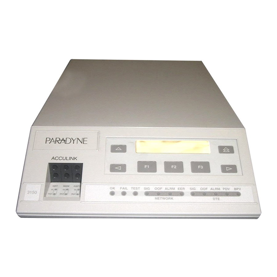
Carrier. For more information about the SDCP, refer to the Series Carrier Installation Manual NOTE: You can display a graphical representation of the CSU front panel on an attached PC (see 3150-A2-GB24-10 (Figure 3-1, Standalone CSU Front Appendix H, Front Panel Emulation March 2001 Panel) -
Page 30: Lcd
3. Using the Front Panel ACCULINK EQPT 3150 Figure 3-1. The LCD (Figure 3-2, Messages such as alarms, command/test completion, and action in progress Front panel menu tree information (see Figure 3-2. The LCD displays status messages as requested via the Device Health and Status branch of the front panel menu (see Chapter 7, Monitoring and Troubleshooting ). -
Page 31: Keypad
Function keys. When your choice appears above one of the Function keys, press that key to select that choice. 3150-A2-GB24-10 (Figure 3-3, Keypad) enables you to navigate through the Keypad key to move up the menu. -
Page 32: Test Jacks
(Figure 3-4, Test Jacks (Standalone Test Jacks in Chapter 8, Testing . EQPT 496-14808 Test Jacks (Standalone CSU) March 2001 appears on the top character appears on 3150-A2-GB24-10... -
Page 33: Leds
System LEDs Network Interface LEDs DTE Interface LEDs Table 3-1. Name Color Green FAIL Yellow TEST Yellow 3150-A2-GB24-10 CSU LEDs (Table 3-1) (Table 3-2) (Table 3-3) System LEDs Meaning Indicates the current operational state of the CSU. ON: The CSU is operational and has power. - Page 34 Indicates the Excessive Error Rate (EER) has been exceeded on the network interface. NOTE: This LED is only valid when ESF framing is being used. ON: The EER has been exceeded on the network interface. OFF: The EER has not been exceeded on the network interface. March 2001 3150-A2-GB24-10...
- Page 35 Table 3-3. Name 3150-A2-GB24-10 DTE Interface LEDs Color Meaning Green Monitors the signal being received from the T1 DTE interface. ON: A recoverable signal is being received from the T1 DTE interface. OFF: The signal cannot be recovered from the T1 DTE interface (a Loss of Signal condition exists).
-
Page 36: Displaying Led Conditions
Off. 4. Use the Appendix H, Front Panel Emulation key until the LED selection appears on Status: TStat ENET LED Display: _Test _NetSig keys to scroll LED names onto the screen. March 2001 ). When using Front 3150-A2-GB24-10... -
Page 37: Displaying Unit Identity
3. Select ID. 4. The following screens appear in the order listed each time you press the key. Ser is the unit’s serial number. Mod is the unit’s model number. 3150-A2-GB24-10 Appendix A, Front Panel Menu CSU ESF Stat Test... - Page 38 MAC is the Ethernet MAC address. CCA is the hardware revision number. 3-10 Identity: Cust ID= xxxxxxxx Identity: SRev= xx . xx . xx Identity: MAC= xx : xx : xx : xx : xx : x Identity: CCA= xxxx - xxx March 2001 3150-A2-GB24-10...
-
Page 39: Resetting The Csu
Press F2 instead to return to the Control screen without initiating a reset. Download Operations NOTE: The Download command is for use by service personnel only. Loss of primary data could result from improper use. 3150-A2-GB24-10 key until the Reset selection appears Control: ClrReg Reset Device Reset: March 2001 3. - Page 40 3. Using the Front Panel 3-12 March 2001 3150-A2-GB24-10...
-
Page 41: Configuration
— Configuring SNMP Traps Enabling the Communication Port for Carrier-Mounted CSUs Deactivating the Alarm Relay for Carrier-Mounted CSUs Configuration options can also be changed using the asynchronous terminal interface (ATI). See 3150-A2-GB24-10 Appendix I, Asynchronous Terminal Interface Operation March 2001... - Page 42 Ctrl selection appears on key until the CID selection appears on Control: Reset Passwd keys to position the cursor under the desired character. moves the cursor to the next space CustID: xxxxxxxx Up Down Save March 2001 3150-A2-GB24-10...
-
Page 43: Changing Configuration Options
These groups are: DTE Interface Configuration Options Network Interface Configuration Options General Configuration Options User Interface Configuration Options Alarm Configuration Options Management Configuration Options 3150-A2-GB24-10 , contains a list of the configuration options and defaults. March 2001 4. Configuration Appendix C,... -
Page 44: Displaying/Editing Configuration Options
2. Select the configuration option set to be copied into the Edit area by using the appropriate Function key. Use the scroll keys, if necessary. 3. Select Edit. Appendix C, Configuration Options CSU ESF Stat Test Cnfig Load from: Activ Cust1 Choose Funct: Edit Save March 2001 3150-A2-GB24-10... - Page 45 5. Press the appropriate Function key to choose another value. Use the scroll keys, if necessary. 6. Use the Save procedure to save your changes to the Active or Customer area. 3150-A2-GB24-10 Edit: NET Framing: ESF Next March 2001 4.
-
Page 46: Saving Edit Changes
Save. 2. Choose whether you want to save to the Active, Customer 1, or Customer 2 area. Use the scroll keys, if necessary. Choose Funct: Edit Save Save Edit to: Activ Cust1 March 2001 3150-A2-GB24-10... -
Page 47: Configuring The 10Baset Port
Function key. Use the scroll keys, if necessary. 3. Select Edit. 4. Select User. 5. Press F1 (Next) until the ENET Use configuration option appears. 6. Select the appropriate protocol for your network. 3150-A2-GB24-10 Edit: User ENET Use: Next 802.3... -
Page 48: Setting The 10Baset Port Ip Address
User selection appears on the Edit: User Alarm Mgmt ENET IP Adr: Next Edit Clear keys to position the cursor under the digit you want to once to place the cursor under the middle digit in 010.000.000.000 Down Save March 2001 3150-A2-GB24-10... -
Page 49: Setting The 10Baset Port Subnet Mask
Press F1 (Up) to increment the digit or F2 (Down) to decrement the digit. 6. When you are through changing the subnet mask, you must press F3 (Save) to save the value. Otherwise, the original value will be retained. 3150-A2-GB24-10 010.155.111.222 Down Save... -
Page 50: Setting The Default Gateway Address
Otherwise, the original value will be retained. 4-10 key until the User selection appears on the Edit: User Alarm Mgmt DefGatewayAdr: Next Edit Clear keys to position the cursor under the digit you want to 000.000.000.000 Down Save 010.155.111.222 Down Save March 2001 3150-A2-GB24-10... -
Page 51: T Configuring The Com Port Or Modem Port For Snmp Or
For SNMP links, configure the device to send traps to the SNMP manager, if desired. Specify the Telnet password or SNMP validation options, if desired (see Appendix C, Configuration Options 3150-A2-GB24-10 Appendix G, IP Network Addressing Scenarios March 2001 4. Configuration... -
Page 52: Selecting The Port
3. Select Edit. 4. Select User. 5. Press F1 (Next) until the Com Use configuration option appears. 6. Select Mgmt to configure the COM port as the SNMP or Telnet link. 4-12 Edit: User Com Use: Next Mgmt ASCII March 2001 3150-A2-GB24-10... -
Page 53: Setting The Com Port Or Modem Port Ip Address
5. Select Mgmt. 6. From the Mgmt Config screen, select Gen. 7. Press F1 (Next) until the Com IP Adr configuration option appears. 3150-A2-GB24-10 Appendix G, IP Network Addressing Scenarios key until the Mgmt selection appears on Edit:... - Page 54 Gen from the Mgmt Config screen and scroll to COM NetMask or Mdm NetMask to change it. 4-14 Com IP Adr: Next Edit Clear keys to position the cursor under the digit you want to once to place the cursor under the 000.000.000.000 Down Save 010.155.111.222 Down Save March 2001 3150-A2-GB24-10...
-
Page 55: Selecting The Link Layer Protocol
Before selecting the protocol, you must first select the port to be used as the communications link. Refer to shows the COM port being used as the communications link. 3150-A2-GB24-10 Selecting the Port on page 4-12. This example March 2001 4. - Page 56 7. Press F1 (Next) until the Com Link configuration option appears. 8. Press F2 (PPP) or F3 (SLIP). 4-16 key until the Mgmt selection appears on Edit: User Alarm Mgmt Mgmt Config: Trap Com Link: Next SLIP March 2001 3150-A2-GB24-10...
-
Page 57: Specifying The Community Name(S) And Access Type(S)
5. Select Mgmt. 6. From the Mgmt Config screen, select Gen. 7. Press F1 (Next) until the CommunityName1 configuration option appears. 8. Press F2 (Edit) to edit the community name. 3150-A2-GB24-10 key until the Mgmt selection appears on Edit: User... - Page 58 4-18 keys to position the cursor under the character you want public Down Save erases all characters to the right of the cursor. Access 1: Next Read March 2001 3150-A2-GB24-10...
-
Page 59: Configuring Snmp Traps
5. Select Alarm. 6. Press F1 (Next) until the SNMP Trap configuration option appears. 7. Press F2 (Enab) to enable trap messages over the SNMP management link. 3150-A2-GB24-10 Appendix C, Configuration Options key until the Alarm selection appears on Edit:... -
Page 60: Selecting The Number Of Trap Managers
7. Select the number of SNMP managers to receive traps (from 1 through 6) by using the appropriate Function key. Use the scroll keys, if necessary. 4-20 key until the Mgmt selection appears on Edit: User Alarm Mgmt Mgmt Config: Trap Num Trap Mgrs:1 Next March 2001 3150-A2-GB24-10... -
Page 61: Configuring A Destination For Snmp Traps
9. Press F1 (Next) until the Trap n Destination configuration appears, and select the destination for the SNMP trap by using the appropriate Function key. Use the scroll keys, if necessary. 3150-A2-GB24-10 key until the Mgmt selection appears on Edit:... -
Page 62: Enabling The Communication Port For Carrier-Mounted Csus
6. Select Enab to enable the COM port for the carrier-mounted CSU. 4-22 COMSPHERE 3000 Series Carrier .) Unlike standalone CSUs, the carrier-mounted CSUs do not key until User is displayed. Select User. Edit: User Com Port: Next Enab Disab March 2001 3150-A2-GB24-10... - Page 63 The caret (“^”) control character is used to select non-printable ASCII characters. The caret “^” must be followed by one character which together form the control sequence. available control sequences. 3150-A2-GB24-10 Table 4-1, Control Sequences, defines all of the March 2001 4.
- Page 64 LF or NL FF or NP March 2001 0x01 0x02 0x03 0x04 0x05 0x06 0x07 0x08 0x09 0x0A 0x0B 0x0C 0x0D 0x0E 0x0F 0x10 0x11 0x12 0x13 0x14 0x15 0x16 0x17 0x18 0x19 0x1A 0x1B 0x1C 0x1D 0x1E 0x1F 3150-A2-GB24-10...
-
Page 65: Deactivating The Alarm Relay For Carrier-Mounted Csus
To deactivate the alarm relay: 1. From the top-level menu screen, press the appears on the screen. 2. Select Ctrl. 3. From the Control screen, select ACO. 4. The Command Complete screen appears. 3150-A2-GB24-10 Control: Alarm Cut-Off: Command Complete March 2001 4. Configuration... - Page 66 4. Configuration 4-26 March 2001 3150-A2-GB24-10...
-
Page 67: Security
Security Overview This chapter describes: Establishing Access Security on a Port Setting a Password Entering a Password to Gain Access Acquiring/Releasing the User Interface Enabling/Disabling the Front Panel User Interface Access Security for Standalone CSUs 3150-A2-GB24-10 March 2001... - Page 68 5. Press F1 (Next) until the Password configuration option appears. 6. Select port(s) to receive access security (None, Com, Modem, or Both). Use the scroll keys, if necessary. on page 5-3). key until User is displayed. Select User. Edit: User Password:None Next None March 2001 3150-A2-GB24-10...
- Page 69 Valid password characters are 0–9, a–z, A–Z, #, –, ., and /. Press F3 (Save) to save the password. 3150-A2-GB24-10 on page 5-2) the password itself is set. key until the Passwd selection appears...
- Page 70 Invalid Password appears. on page 5-3). Passwd:_ Down Done keys to position the cursor under the desired character. key moves the cursor to the next key is not destructive. Passwd: xxxxxxxx Down Done March 2001 3150-A2-GB24-10...
-
Page 71: Acquiring The Active User Interface
On the screen, either Ft. Panel (front panel), Com Port, Modem, or SDCP is displayed in the user interface ( User I/F ) field. 3150-A2-GB24-10 1: 1 CSU ESF Stat... -
Page 72: Releasing The Active User Interface
3. From the Control screen, select Rel (Release). The active user interface is released. The message Released appears. No user interface is active until input is received from a user interface. 1: 1 CSU ESF User I/F idle Control: March 2001 key until the Ctrl selection 3150-A2-GB24-10... -
Page 73: Enabling/Disabling The Front Panel
Function key. Use the scroll keys, if necessary. 3. Select Edit. 4. Select User. 5. Press F1 (Next) until the FP Access configuration option appears. 6. Press F2 to enable the front panel or F3 to disable the front panel. 3150-A2-GB24-10 FP Access: Next Enab Disab March 2001 5. - Page 74 5. Security March 2001 3150-A2-GB24-10...
-
Page 75: User Interface Access Security For Standalone Csus
All functions on the Cnfg branch are available for display, but they cannot be used to save to a configuration area. You can only reach the screen that controls security access using the front panel. 3150-A2-GB24-10 March 2001 5. Security... -
Page 76: Changing User Interface Access Security
If you do not make a selection within 5 minutes, the Automatic Device Health/Status screen appears. 5-10 key two times from the top-level screen. CSU ESF Stat Test Cnfig key three times. CSU ESF Stat Test Cnfig key once. CSU ESF Stat Test Cnfig Security: Lvl1 Lvl2 March 2001 3150-A2-GB24-10... -
Page 77: Using The Integral Modem
PC. Sets up a semipermanent connection to route alarm messages to the specified destination. Disconnect – Disconnects an active modem connection. Change Directory – Allows entry of phone numbers into the internal phone directories. For additional information, refer to Appendix C, Configuration Options . 3150-A2-GB24-10 User Interface Configuration Options March 2001... -
Page 78: Entering Numbers In The Phone Directories
(Previous) to display the previous directory (A, in this case). Directories appear in order, 1 through 5 and then A. Control: Call Call Setup: Dial Disc ChDir 1: xxxxxxxxxxxxxxxxx Next Prev Edit March 2001 key until the Ctrl selection 3150-A2-GB24-10... - Page 79 Table 6-1, Valid Phone Number and rules that apply to entering phone numbers. Example: P9W8135551212 8. Press F3 (Save) to store your changes in nonvolatile memory. If you press phone number remains in effect. 3150-A2-GB24-10 1: xxxxxxxxxxxxxxxxx Next Prev Edit...
-
Page 80: Initiating A Call For Front Panel Pass-Through Operation
Tone is the default. This must be the first character in the string, unless the first character is B. Then, it must immediately follow the B. — To be valid, this must be the first character in the string. — — — 3150-A2-GB24-10... - Page 81 5. From the Pass Directory screen, press F1 (Up) to display the next higher numbered directory or press F2 (Down) to select the next lower numbered directory. 6. When the number of the desired directory appears on the screen, press F3 (Dial) to place the call. 3150-A2-GB24-10 Control: Call ClrReg Call Setup:...
-
Page 82: Initiating A Call For Pc, Ascii Terminal/Printer, Or Snmp Operation
6. When the number of the desired directory appears on the screen, press F3 (Dial) to place the call. Control: Call ClrReg Call Setup: Pass Dial ChDir Dial n : xxxxxxxxx Down Dial Dial n : xxxxxxxxx Down Dial March 2001 key until the Ctrl selection 3150-A2-GB24-10... -
Page 83: Disconnecting The Modem Connection
Disconnect methods include: Using the Disconnect command via the front panel menu (for all dial connections, or when a pass-through connection is established to another 3150 CSU). Pressing and holding the pass-through connection is established to a remote device other than a 3150 CSU). - Page 84 6. Using the Integral Modem Procedure To disconnect a modem connection using two front panel keys: 1. Press the The modem call is disconnected and the Command Complete screen appears. keys simultaneously and hold for two seconds. Call Setup: Disc ChDir March 2001 3150-A2-GB24-10...
-
Page 85: Monitoring And Troubleshooting
Device Health and Status Messages Performance Reports Ethernet Statistics Alarms SNMP Traps In addition, this chapter contains a troubleshooting table that shows how to use messages and the behavior of the CSU to diagnose and correct problems. Troubleshooting 3150-A2-GB24-10 March 2001... - Page 86 3. View the results of the last power-on self-test. If no problems were found during power-on, the following message appears. Table 7-1, Self-Test Health , for more information about power-on self-test. CSU ESF Stat Test Cnfig Status: DevHS STest Perf STest Health: Passed March 2001 Messages. See 3150-A2-GB24-10...
- Page 87 LCD fail Memory fail Modem fail NET T1 fail Passed 3150-A2-GB24-10 Self-Test Health Messages Description The unit failed to transmit AIS or to detect an Yellow alarm. The unit failed to encode data properly or to detect Loss Of Signal.
- Page 88 (no keys pressed) on the active physical interface for five minutes. Only the highest priority message appears on Line 2 of the LCD. Table 7-2, Health and Status Status: DevHS STest Perf Device H/S: OOF at DTE Auto Dev H/S OOF at DTE March 2001 Messages, lists these 3150-A2-GB24-10...
- Page 89 OOF at Net Selftest failed Test in progress Yellow at DTE Yellow at Net 3150-A2-GB24-10 Health and Status Messages Description An Alarm Indication Signal is being received by the DTE interface. An Alarm Indication Signal (unframed all ones signal) is being received by the network interface.
- Page 90 To display User Network Interface (User) performance: 1. From the top-level menu screen, select Stat. 2. From the Status screen, select Perf. 3. Select User registers. Table 7-3, Performance Status: DevHS STest Perf Performance: Telco User March 2001 Registers. 3150-A2-GB24-10...
- Page 91 7. When you press F3 from the User Registers screen, the interval screen appears. Use this screen to choose the specific 15-minute interval. 8. Use the the interval number displayed, then use the F1 (Up) and F2 (Down) keys to increment/ decrement the number. 3150-A2-GB24-10 Step User Registers: 24Tot Intvl...
- Page 92 24-hour counts are reset to zero. The Command Complete message then appears. User Intvl: xx ES= xxx Control: Call ClrReg Clear Prf Regs: User March 2001 key until the Ctrl selection 3150-A2-GB24-10...
- Page 93 Table 7-3. Register Event CurTimer VldIntvl LOFC 3150-A2-GB24-10 Performance Registers (1 of 2) Interval Description ESF error events counter. An error event is an ESF frame with either a Cyclic Redundancy Check (CRC) error or an Out Of Frame (OOF) event.
- Page 94 The Excessive Error Rate threshold has been exceeded. – A Frame Synchronization Bit Error has been detected. – A Bipolar Violation has been detected. If none of these events occurred during the interval, StEvnt=none will be displayed. March 2001 Totals Description 3150-A2-GB24-10...
-
Page 95: Ethernet Statistics
1. From the top-level menu screen, select Stat. 2. From the Status screen, select ENET. 3. Ethernet statistics are displayed. Press the the statistics. Table 7-4. Symbol Coll CErr 3150-A2-GB24-10 Status: Perf TStat ENET Ethernet: TX= xxxxxxxxxx Ethernet Statistics Description Frames transmitted. -
Page 96: T Alarms
For information about alarm configuration options, refer to Options in Appendix C, Configuration Options . For troubleshooting information, refer to 7-12 in Chapter 3, Using the Front Panel . Troubleshooting on page 7-15. March 2001 Alarm Configuration 3150-A2-GB24-10... -
Page 97: Snmp Traps
Link Trap configuration option. The communications interfaces for which these traps can be generated are specified by the Trap I/F configuration option. Table 7-6, SNMP Trap per 3150-A2-GB24-10 7. Monitoring and Troubleshooting Appendix C, Configuration Options Table 7-5, Enterprise-Specific Trap Interface, defines traps for each interface. - Page 98 Trap Meaning Up = No alarm or test conditions. Down = Alarm or test conditions. Up = No alarm or test conditions, and the interface is enabled. Down = Alarm or test conditions, or the interface is disabled. March 2001 3150-A2-GB24-10...
-
Page 99: Troubleshooting
8-digit code Invalid Number LOS at DTE message appears LOS at NET message appears 3150-A2-GB24-10 Troubleshooting, to determine your course of action if a problem Troubleshooting (1 of 2) Possible Cause 1. Upstream device is transmitting an AIS. 2. The network is transmitting an AIS. - Page 100 1. Check the status of the DTE. 2. Check that the DTE cable is securely attached at both ends. 1. Check that your network cable is securely attached at both ends. 2. Check the status of the far-end device. 3. Contact your facility provider. 3150-A2-GB24-10...
-
Page 101: Testing
This chapter explains the functions of the test jacks, and shows how to use test commands to perform the following: Remote Loopback Tests Local Loopback Tests Test Patterns Lamp Test Displaying CSU Test Status 3150-A2-GB24-10 March 2001... -
Page 102: Test Jacks
Jacks). The Mon (Monitor) branch of the menu tree allows you to Jacks. Figure 8-3, Test Jack Block Table 8-1, Test Jack Functions. EQPT 496-14808 Model 3150 Test Jacks 01-16943 Model 3151 Test Jacks March 2001 (Figure 8-1, Figure 8-2, Diagram, and... - Page 103 A break-in test jack that interrupts the signal coming from the network and allows it to be terminated by the external test equipment. Model 3150: A break-in test jack that allows a signal to be inserted toward the terminal equipment (DTE) by external test equipment.
-
Page 104: Test Jack Configuration (Model 3150)
8. Testing Test Jack Configuration (Model 3150) Procedure To change the Mon (Monitor) selection: 1. From the top-level menu, press the the screen. 2. Select Ctrl. 3. From the Control screen, press the the screen. 4. Select Mon. 5. From the Mon Jack screen, press F1 to select EQPT (the default), or press F2 to select NET. -
Page 105: Test Commands
CSU. Procedure To send a Line Loopback Up or Down sequence on the network to a far-end CSU: 1. From the top-level menu screen, select Test. 2. From the Test screen, select Rlpbk. 3150-A2-GB24-10 CSU ESF Stat Test Cnfig... -
Page 106: Local Loopback Tests
No more than two local loopbacks can be active at any one time. An additional restriction prohibits certain loopbacks from running at the same time. Valid loopback combinations listed in identified by YES. Table 8-2. Rem Loopback: LLBUP LLBDN Table 8-2, Valid Loopback Valid Loopback Combinations March 2001 Appendix C, Combinations, are 3150-A2-GB24-10... - Page 107 Test Started appears on Line 2. If a line loopback is already in progress, the Already Active message appears. If an invalid combination of loopbacks is in progress, the error message Invld Test Combo appears (see Table 8-2, Valid Loopback combinations). 3150-A2-GB24-10 Test: Rlpbk Lpbk Ptrns Loopback:...
- Page 108 Already Active message appears. If an invalid combination of loopbacks is in progress, the error message Invld Test Combo appears (see Table 8-2, Valid Loopback combinations). Test: Rlpbk Lpbk Ptrns Loopback: Abort Combinations, for valid loopback test March 2001 3150-A2-GB24-10...
- Page 109 Test Started appears on Line 2. If a DTE loopback is already in progress, the Already Active message appears. If an invalid combination of loopbacks is in progress, the error message Invld Test Combo appears (see Table 8-2, Valid Loopback combinations). 3150-A2-GB24-10 Test: Rlpbk Lpbk Ptrns key until the DLB selection appears...
- Page 110 Already Active message appears. If an invalid combination of loopbacks is in progress, the error message Invld Test Combo appears (see Table 8-2, Valid Loopback combinations). 8-10 Test: Rlpbk Lpbk Ptrns key until the RLB selection appears Loopback: Combinations, for valid loopback test March 2001 3150-A2-GB24-10...
-
Page 111: Aborting Loopbacks
If you mistakenly choose to abort a loopback test that is not currently running, a Command Complete message will still display and the loopback that is currently active will still be running. Use the TStat branch to view the test status to determine if the abort was successful. 3150-A2-GB24-10 Test: Rlpbk Lpbk... -
Page 112: Test Patterns
3. From the Patterns screen, select Send. 4. From the Patterns Send screen, press F1 to send a QRSS pattern or F2 to send a 1-in-8 pattern. 8-12 Test: Rlpbk Lpbk Ptrns Patterns: Abort Send Patterns: Send QRSS 1in8 March 2001 3150-A2-GB24-10... -
Page 113: Monitoring Test Patterns
The Monitor screen appears with the error count. If the maximum of 99999 is exceeded, OvrFlw appears instead of the count. If the receiver loses synchronization while the monitor is active, No Sync appears. 3150-A2-GB24-10 Send: Name Test Started Test:... -
Page 114: Aborting Test Patterns
Command Complete message still displays and the test pattern currently active still runs. Use the TStat branch to view the test status to determine if the abort was successful. 8-14 Test: Rlpbk Lpbk Ptrns Patterns: Abort Send Patterns: Abort Send March 2001 3150-A2-GB24-10... -
Page 115: Lamp Test
4. From the Lamp Test screen, select Start. 5. The following screens alternately appear on the LCD until you press a Function key to return to the Lamp Test screen. In addition, all LEDs blink. 3150-A2-GB24-10 key until the Lamp selection appears on Test:... -
Page 116: Aborting A Lamp Test
Lamp test screens, press any Function key. Otherwise, follow Step 3 2. From the Lamp Test screen, select Abort. 8-16 on page 8-15 for starting a Lamp test. Lamp Test: Abort Start Lamp Test: Abort Start March 2001 Step 1 through 3150-A2-GB24-10... -
Page 117: Displaying Csu Test Status
PLB Test Active DLB Test Active RLB Test Active QRSS on Net 1–8 Test Active Mon QRSS, Net DLB Test, Extrn Lamp Test Active 3150-A2-GB24-10 key until the TStat selection appears on Status: STest Perf TStat Test Status Messages Description No tests are currently active. - Page 118 8. Testing 8-18 March 2001 3150-A2-GB24-10...
-
Page 119: A Front Panel Menu
Front Panel Menu Stat DevHS STest Perf TStat ENET LED Telco User Rlpbk 24Tot Intvl LLBUP LLBDN Abort For Carrier-Mounted CSUs only For Standalone CSUs only 3150-A2-GB24-10 CSU ESF Test Cnfig Call Pass Lamp Lpbk Ptrns 1 . . 5,A (Directory) Abort... - Page 120 A. Front Panel Menu March 2001 3150-A2-GB24-10...
-
Page 121: Technical Specifications
Additional APPROVALS 3150-A2-GB24-10 Specifications. The technical specifications for ACCULINK 3151 CSU and 3161 DSU/CSU Model 3150 CSU Technical Specifications (1 of 2) Criteria 7.4 watts, 25.2 Btu per hour at 115 Vac, 60 Hz (includes external transformer) DB15 socket D4, ESF AMI, B8ZS 5 selectable ranges from 0 to 655 feet (0 to 196.5 meters) - Page 122 Depth WEIGHT ENVIRONMENT Operating Temperature Storage Temperature Relative Humidity Shock and Vibration Model 3150 CSU Technical Specifications (2 of 2) Criteria RJ11C (USA), CA11A (Canada) 2400 bps V.22bis 2.13 inches (5.4 cm) 7.63 inches (19.4 cm) 12.13 inches (30.8 cm) 2.1 pounds (1.0 kg)
-
Page 123: Configuration Options
The configuration tables include a description of each configuration function and its available selections. In the tables, the top line of each configuration option entry indicates the factory default setting. 3150-A2-GB24-10 (Table C-2, Network Interface Configuration Options). (Table C-4, User Interface Configuration (Table C-5, Alarm Configuration Options). - Page 124 8 zeros on the Facility Data Link (FDL). – Enab Transcodes the signal transmitted to the DTE. – Disab Disables transcoding. D4 (Factory 2) Prev AMI (Factory 2) B8ZS Prev 133—266 266—399 399—533 Disab Prev Disab Prev Disab Prev March 2001 533—655 Prev 3150-A2-GB24-10...
-
Page 125: Network Interface Configuration Options
NOTES: – This configuration option is only available if the framing format is set to ESF. – If the local CSU’s FDL is enabled, the remote CSU’s FDL must also be enabled. 3150-A2-GB24-10 D4 (Factory 2) Prev AMI (Factory 2) - Page 126 – To comply with Canadian DOC CS-03 regulations, equipment installed in Canada must be configured to select 62411. – This configuration option is only available if the network interface line coding format is set to AMI. Disab Prev Disab Prev Disab Prev March 2001 3150-A2-GB24-10...
- Page 127 DTE. When NET Framing is set to D4, framing bits are not recalculated before being sent to the DTE. – Disab Any framing or CRC bits that are in error are recalculated before being sent to the DTE. 3150-A2-GB24-10 NetLp Prev Disab Prev Clear...
-
Page 128: General Configuration Options
Use the Function keys (Up or Down) to increment or decrement the digit. – Increments the test duration. – Down Decrements the test duration. – Save Stores the test duration. Disab Prev Down Save Prev March 2001 3150-A2-GB24-10... -
Page 129: User Interface Configuration Options
Prevents dial-in access. Incoming calls to the CSU are not answered. NOTE: To enable Dial-In for carrier-mounted CSUs, the external device must be configured for automatic answer and the ComExtDev configuration option must be enabled. 3150-A2-GB24-10 Disab Prev Disab Prev... - Page 130 Therefore, do not allow the CD lead to be forced on by the external device. – The external device should be strapped to ignore Data Terminal Ready (DTR). Modem Both Prev Prompts the remote modem port user to enter a password. Disab Prev ASCII Term Prev Other Prev March 2001 3150-A2-GB24-10...
- Page 131 NOTES: – This configuration option is available on carrier-mounted CSUs only. – This configuration option is not available if the ComExtDev configuration option is set to AT or the communication port is disabled. 3150-A2-GB24-10 Clear Prev Clear Prev March 2001 C.
- Page 132 AT or the communication port is disabled. – ComEscDel must be configured for a delay greater than or equal to the escape guard time required by the external device. C-10 Clear Prev 0.2s 0.4s 0.6s 0.8s 1.0s March 2001 Prev 3150-A2-GB24-10...
- Page 133 – Configures the communication port for internal clocking. – Configures the communication port for external clocking. NOTE: This configuration option is not available if the Com Type configuration option is set to Async. 3150-A2-GB24-10 Clear Prev Sync Prev Prev March 2001 C.
- Page 134 Data Terminal Ready (DTR) input to the communication port. – DTR is ignored. – DTR is not ignored. NOTE: This configuration option is not available if the communication port is configured for synchronous operation. C-12 14.4 19.2 38.4 Prev Even Prev Prev Prev March 2001 Prev 3150-A2-GB24-10...
- Page 135 Modem Port Rate. Configures the bit rate for the modem port. – Sets the bit rate at 1200 bps. – Sets the bit rate at 2400 bps. NOTE: This configuration option is available on standalone CSUs only. 3150-A2-GB24-10 Disab Prev Down Save Prev...
- Page 136 The modem port disconnects after the period of inactivity specified by the MoDiscTm configuration option. – Disab The modem port does not disconnect due to inactivity. NOTE: This configuration option is available on standalone CSUs only. C-14 Prev Even Prev Prev Disab Prev Disab Prev March 2001 3150-A2-GB24-10...
- Page 137 IP address (Class A: 255.000.000.000, Class B: 255.255.000.000, or Class C: 255.255.255.000). NOTE: This configuration option is not displayed if 10BaseT port use (ENET Use) is disabled. It is available on standalone CSUs only. 3150-A2-GB24-10 Down Save Prev...
- Page 138 Use the Function keys (Up or Down) to increment or decrement the digit. – Increments the time delay. – Down Decrements the time delay. – Save Stores the time delay for use with inactivity disconnects. C-16 Clear Prev Disab Prev Disab Prev Disab Prev Down Save Prev March 2001 3150-A2-GB24-10...
-
Page 139: Alarm Configuration Options
NOTE: This configuration option is only available if SNMP traps are enabled and the integral modem or the carrier external communication port device is enabled and configured as an SNMP management link. 3150-A2-GB24-10 Modem Both Prev Enables alarm messages routed to the modem port. - Page 140 The factory default is 5 minutes. NOTE: For carrier-mounted CSUs, this configuration option is only available if the communication port is enabled for an external device. C-18 Disab Prev Disab Prev March 2001 Prev 3150-A2-GB24-10...
- Page 141 10E-7 – EER is declared if more than 9 CRC6 errors are detected within 60 seconds. 10E-8 – EER is declared if more than 41 CRC6 errors are detected in three 15-minute intervals. 10E-9 – EER is declared if more than 4 CRC6 errors are detected in three 15-minute intervals. 3150-A2-GB24-10 Prev 10E-5 10E-6 10E-7...
- Page 142 Alarm Indication Signal (AIS) received at either the network or 7DTE interface. Yellow alarm signal received at either the network or DTE interface. Excessive Error Rate (EER) detected at the network interface. NOTE: This configuration option is available on carrier-mounted CSUs only. C-20 Disab Prev March 2001 3150-A2-GB24-10...
-
Page 143: Management Configuration Options
Allows you to edit and/or display the allowable IP address for the SNMP manager. – Clear Allows you to clear the allowable IP address for the SNMP manager. The IP address is set to 000.000.000.000. 3150-A2-GB24-10 (Table Disab Prev Disab... - Page 144 MIB. – Edit Allows you to edit or display the first community name. – Clear Allows you to clear the first community name. C-22 Prev Clear Prev Clear Prev Clear Prev Clear Prev March 2001 3150-A2-GB24-10...
- Page 145 – Edit Allows you to edit and/or display the IP address for the CSU. – Clear Allows you to clear the IP address for the CSU. The IP address is set to 000.000.000.000. 3150-A2-GB24-10 Prev Clear Prev Prev Clear Prev March 2001 C.
- Page 146 The communication port must be configured for asynchronous operation to support SLIP. NOTE: This configuration option is not available on carrier-mounted CSUs if the communication port is disabled. C-24 Clear Prev Clear Prev Clear Prev SLIP Prev March 2001 3150-A2-GB24-10...
- Page 147 Mask is set to 000.000.000.000. If the Subnet Mask is 000.000.000.000, the IP protocol creates a default Subnet Mask based on the class of the IP address (Class A: 255.000.000.000, Class B: 255.255.000.000, or Class C: 255.255.255.000). NOTE: This configuration option is available on standalone CSUs only. 3150-A2-GB24-10 Clear Prev Clear...
- Page 148 NOTE: If the chosen default network link is disabled or down, data is discarded. Return to this menu and choose another default network. C-26 SLIP Prev Disab Prev IPBus Modem The default network destination is the modem port. This selection appears only March 2001 Prev 3150-A2-GB24-10...
- Page 149 The Trap Manager n network destination is the FDL management link. This selection appears only if the FDL management link is enabled. NOTE: If the chosen destination link is disabled or down, the traps are discarded. Return to this menu and choose another destination. 3150-A2-GB24-10 Prev Clear Prev...
- Page 150 NOTE: This configuration option is not available if the SNMP Trap configuration option (see Table C-5, Alarm Configuration C-28 Warm Auth Both Prev Options) is disabled. Disab Prev Options) is disabled. Down Both Prev Options) is disabled. March 2001 3150-A2-GB24-10...
-
Page 151: Dte Interface
Sends trap messages for linkUp and linkDown events occurring on both the network and DTE interface. NOTE: This configuration option is not available if the Link Trap configuration option is not configured to generate trap messages for linkUp or linkDown events. 3150-A2-GB24-10 Both Prev March 2001 C. - Page 152 C. Configuration Options C-30 March 2001 3150-A2-GB24-10...
- Page 153 Configuration Worksheets Configuration Worksheets This section contains one set of blank worksheets to be used when configuring your DSU/CSU in the network. In the tables, default settings for Factory 1 are indicated by bold type. 3150-A2-GB24-10 March 2001...
- Page 154 D4, ESF AMI, B8ZS 0.0, –7.5, –15, –22.5 Enab, Disab Enab, Disab Enab, Disab Enab, Disab 62411, Part68, Disab AIS, One, NetLp Enab, Disab Edit, Clear Enab, Disab Value (Default in Bold) Enab, Disab 1–120 (Default = 10) March 2001 3150-A2-GB24-10...
- Page 155 Ignore DTR CmInActTm CmDiscTm Modem Use Modem Type Modem Rate MChar Len MParity MStop Bits LSpaceDisc 3150-A2-GB24-10 D. Configuration Worksheets Value (Default in Bold) Enab, Disab Enab, Disab Enab, Disab Enab, Disab None, Com, Modem, Both Enab, Disab Mgmt, ASCII, Term...
- Page 156 Value (Default in Bold) Disab, Modem, Com, Both Enab, Disab Enab, Disab Enab, Disab Enab, Disab 1, 2, 3, 4, 5, 6, 7, 8, 9, 10 None, 1, 2, 3, 4, 5 10E-4, 10E-5, 10E-6, 10E-7, 10E-8, 10E-9 Enab, Disab March 2001 3150-A2-GB24-10...
- Page 157 Modem IP Adr Mdm NetMask Alt Mdm IP Adr Alt Mdm NetMask Modem Link IPBusMast Def Netwk 3150-A2-GB24-10 D. Configuration Worksheets Value (Default in Bold) Enab, Disab Enab, Disab 1, 2, 3, 4, 5, 6, 7, 8, 9, 10 Edit, Clear...
- Page 158 DSU/CSUs only. Value (Default in Bold) 1, 2, 3, 4, 5, 6 Edit, Clear None, IPBus, Com, Modem, FDL Disab, Warm, Auth, Both Enab, Disab Disab, Up, Down, Both NET, DTE, T1s, Ports, All March 2001 3150-A2-GB24-10...
-
Page 159: Pin Assignments
Pin 1 is at the lower right of the connector and Pin 6 at the upper left as you face the back of the unit. Table E-1. Signal +24 Vdc +24 Vdc Return Chassis Ground 3150-A2-GB24-10 DC Power Connector Pin Number March 2001 Appendix J, Table E-1, DC Power Connector. - Page 160 The T1 line interface cable is a 20-foot, 24 AWG solid, 2-twisted pair cable that is either RJ48C-to-RJ48C RJ48C-to-DA15P Table E-2. Signal Receive Ring Receive Tip Transmit Ring Transmit Tip Connector). (Figure E-1, T1 Line Interface Cable, (Figure E-2, T1 Interface Cable, T1 Network Interface Connector Pin Number March 2001 RJ48C-to-RJ48C) or RJ48C-to-DA15P). 3150-A2-GB24-10...
- Page 161 PLUG UNKEYED BLUE RECEIVE RING RECEIVE TIP WHITE/BLUE ORANGE TRANSMIT RING TRANSMIT TIP WHITE/ORANGE Figure E-2. 3150-A2-GB24-10 TWISTED PAIR TWISTED PAIR T1 Line Interface Cable, RJ48C-to-RJ48C WHITE/BLUE WHITE/ORANGE T1 Interface Cable, RJ48C-to-DA15P March 2001 E. Pin Assignments RJ48C PLUG UNKEYED...
- Page 162 Cable) is typically supplied by a DTE vendor. It is DTE Connector Pin Number PLUG TWISTED PAIR TWISTED PAIR DTE Cable March 2001 (Table E-3, DTE DTE Interface DB15 RECEIVE TIP RECEIVE RING SHIELD GROUND TRANSMIT TIP TRANSMIT RING SHIELD GROUND RETURN SENSE 494-14152-02 3150-A2-GB24-10...
-
Page 163: Modem Port Interface
The integral modem VF cable is a 14.5-foot, 26 AWG, 4-conductor keyed cable with an RJ11C-like plug connector is supplied with your standalone CSU. Table E-4. Signal VF Ring VF Tip RING Figure E-4. 3150-A2-GB24-10 Connector). (Figure E-4, Integral Modem Integral Modem Port Connector Pin Number RJ11 RJ11 PLUG PLUG... -
Page 164: 10Baset Connector
DSU. The following table defines the pinouts for the 10BaseT port. It is an 8-pin, unkeyed jack. Transmitted Data + Transmitted Data – Received Data + Received Data – NC = Not connected (unused). Pin Number March 2001 3150-A2-GB24-10... -
Page 165: Com Port Interface
DCE Transmit Clock DCE Receive Data Signal Ground DCE Transmit Data DCE Data Terminal Ready DCE Carrier Detect DCE Request-to-Send DCE Receive Clock 3150-A2-GB24-10 (Table E-5, COM Port Figure E-5, COM Port-to-PC Cable Cable. COM Port Connector Direction From CSU From CSU —... - Page 166 Figure E-5. 8-POSITION MODULAR PLUG KEYED RX DATA GROUND TX DATA Figure E-6. NO CONNECTION NO CONNECTION COM Port-to-PC Cable COM Port-to-Terminal/Printer Cable March 2001 SOCKET RX DATA GROUND TX DATA 494-14153-02 DB25 PLUG RX DATA GROUND TX DATA 494-14154-02 3150-A2-GB24-10...
-
Page 167: Serial Crossover Cable
Cable) to connect an external modem to the CSU’s COM port. Pin 14 Pin 1 Pin 13 Pin 25 Chassis Ground Signal Ground CD (RLSD) Figure E-7. 3150-A2-GB24-10 Figure E-6, COM Port-to-Terminal/Printer Plug Plug Serial Crossover Cable March 2001 E. Pin Assignments Figure E-7, Serial Crossover Pin 1... - Page 168 E. Pin Assignments E-10 March 2001 3150-A2-GB24-10...
-
Page 169: Overview
— An extension to MIB II that defines additional objects for control of generic interfaces in MIB II. Enterprise MIB — Defines objects that are unique to devices such as 315x CSUs. 3150-A2-GB24-10 (Table F-1, SNMP MIB to Front Panel Command March 2001... -
Page 170: System Group, Mib Ii
Supported. Supported. Supported. Supported. Not supported since the EGP protocol is not supported by the CSU. Supported on the T1 interfaces using the DS1/E1 MIB. Supported on the COM and MODEM ports using the RS-232-like MIB. Supported. March 2001 3150-A2-GB24-10... - Page 171 System Group – “sysObjectID” Object (system 2) This object provides the authoritative identification of the network management subsystem contained in the unit. This object displays the following object identifier: 3150 3151 System group – “sysContact” Object (system 4) This object provides a textual identification of the contact person for this managed node.
- Page 172 When an unsupported index is accessed, “noSuchName” is returned. The following are the values of the ifIndexes for all CSU models: 1 – Net T1 2 – DTE T1 3 – COM port 4 – Modem port March 2001 3150-A2-GB24-10...
- Page 173 The supported ifIndexes for the 3150 CSU are: Net T1 DTE T1 COM port Modem port The supported ifIndexes for the 3151 CSU are: Net T1 DTE T1 COM port (if configured) Interface Group – “ifDescr” Object (ifEntry 2) This object provides information about the interface. Each interface displays a text...
- Page 174 The interface is up(1) when no alarm conditions exist and the interface is enabled. The interface is down(2) when an alarm condition is active and the interface is disabled. The interface is testing(3) when a test is active on the interface. March 2001 3150-A2-GB24-10...
- Page 175 (ifEntry 18) ifOutDiscards (ifEntry 19) ifOutErrors (ifEntry 20) ifOutQLen (ifEntry 21) 3150-A2-GB24-10 When configured as an SNMP management link, up and down are based on the current state of the link layer protocol. Otherwise, the interface is always up(1).
- Page 176 “invalid” for the entry to be deleted. An existing route may be modified by changing fields in the desired entry (indexed by ipRouteDest) of the routing table. A new route may be added by specifying values for a table entry for which the index (“ipRouteDest”) does not already exist. March 2001 3150-A2-GB24-10...
- Page 177 Any assignment (implicit or otherwise) of an instance of this object to a value x must be rejected if the bitwise logical – AND of x with the value of the corresponding instance of the ipForwardMask object is not equal to x .” 3150-A2-GB24-10 March 2001 F. SNMP MIB Objects...
- Page 178 For temporary routes, the ipRouteAge object decrements over time. All routes added via an SNMP set of the ipRouteTable are considered permanent routes. These routes do not age, but will remain unless deleted via SNMP. F-10 March 2001 3150-A2-GB24-10...
- Page 179 CSU. The following objects apply only to an NMS and return a zero value if accessed. snmpInTooBigs (snmp 8) snmpInNoSuchNames (snmp 9) snmpInBadValues (snmp 10) snmpInReadOnlys (snmp 11) snmpInGenErrs (snmp 12) snmpInGetResponses (snmp 18) snmpInTraps (snmp19) snmpOutGetRequests (snmp 25) snmpOutGetNexts (snmp 26) snmpOutSetRequests (snmp 27) 3150-A2-GB24-10 March 2001 F. SNMP MIB Objects F-11...
-
Page 180: Ds1/E1 Mib (Rfc 1406)
This object corresponds to the NET Coding/DTE Coding configuration options for the T1 interfaces on the CSU. Only the following values are supported by the CSU. dsx1B8ZS(2) – Indicates B8ZS line coding. dsx1AMI(5) – Indicates AMI line coding. F-12 March 2001 3150-A2-GB24-10... - Page 181 Repeater Loopback (RLB) is active for the DTE interface. dsx1LineLoop(3) – Specifies that a Line Loopback (LLB) is active for the network interface or a DTE Loopback (DLB) is active for the DTE interface. 3150-A2-GB24-10 March 2001 F. SNMP MIB Objects F-13...
- Page 182 – The recovered receive clock is being used as the transmit clock. localTiming(2) – The CSU’s internal clock is being used as the transmit clock. ThroughTiming(3) – The recovered receive clock from another interface (e.g., T1, Port, or External) is being used as the transmit clock. F-14 March 2001 3150-A2-GB24-10...
- Page 183 – Errored Seconds for the interval. dsx1Interval SESs – Severely Errored Seconds for the interval. dsx1IntervalUASs – Unavailable Seconds for the interval. dsx1Interval BESs – Bursty Errored Seconds for the interval. 3150-A2-GB24-10 March 2001 F. SNMP MIB Objects F-15...
-
Page 184: Far End Group, Ds1/E1 Mib
These tables are not supported for either the network or DTE interface. DS1 Fractional Group, DS1/E1 MIB The DS1 Fractional Group consists of the DS1 fractional table. This table (dsx1FracTable) is not supported by the CSU. F-16 March 2001 3150-A2-GB24-10... -
Page 185: Rs-232-Like Mib (Rfc 1317)
Number of Ports – “rs232Number” Object (rs232 1) This object contains the number of ports in the RS-232-like general port table. This number is 3 for the 3150 CSU and 1 for the 3151 CSU when the COM port is enabled. -
Page 186: Asynchronous Port Table, Rs-232-Like Mib
Asynchronous Port Table, “rs232AsyncPortBits” (rs232AsyncPortEntry 2) This object specifies the number of bits in a character. Only the following values are supported by the CSU. 7 – 7-bit characters. Supported on the COM and MODEM ports only. 8 – 8-bit characters. F-18 March 2001 3150-A2-GB24-10... -
Page 187: Synchronous Port Table, Rs-232-Like Mib
This object specifies the clock source for the port. Only the following values are supported by the CSU. internal(1) – The port uses an internal clock. external(2) – The port uses an external clock. 3150-A2-GB24-10 March 2001 F. SNMP MIB Objects F-19... -
Page 188: Generic-Interface Mib Extensions (Rfc 1229)
– No test currently active. inProgress(3) – A test is currently in progress. notSupported(4) – The requested test is not supported. unAbleToRun(5) – The requested test cannot run due to the state of the unit. F-20 March 2001 3150-A2-GB24-10... -
Page 189: Enterprise Mib
SNMP database. SNMP objects are displayed in bold type while values for SNMP objects are displayed in italics. 3150-A2-GB24-10 Cross-Reference, provides a March 2001 F. SNMP MIB Objects... - Page 190 Net T1 testMonQRSS from ifExtnsTestType for Net T1 Read the sysDescr object from the System Group Set dsx1SendCode to dsx1SendLineCode Set dsx1SendCode to dsx1SendResetCode Set dsx1LoopbackConfig for Net T1 to dsx1LineLoop Set dsx1LoopbackConfig for Net T1 to dsx1NoLoop March 2001 3150-A2-GB24-10...
- Page 191 Cnfig–>Activ–>Edit–>User–>MChar Len Cnfig–>Activ–>Edit–>User–>CParity Cnfig–>Activ–>Edit–>User–>MParity Cnfig–>Activ–>Edit–>User–>CStop Bits Cnfig–>Activ–>Edit–>User–>MStop Bits 3150-A2-GB24-10 SNMP MIB Object Set dsx1LoopbackConfig for Net T1 to dsx1PayloadLoop Set dsx1LoopbackConfig for Net T1 to dsx1NoLoop Set dsx1LoopbackConfig for DTE T1 to dsx1LineLoop Set dsx1LoopbackConfig for DTE T1 to dsx1NoLoop...
- Page 192 F. SNMP MIB Objects F-24 March 2001 3150-A2-GB24-10...
-
Page 193: Overview
Although the default route (to the NMS) is configurable for all devices, only devices that have a direct external connection to an NMS need a default route set. In the following examples, the default port is set in the device connected to the LAN. 3150-A2-GB24-10 March 2001... -
Page 194: Standalone At The Central Site
135.18.1.2 135.18.1.3 135.18.1.4 135.18.1.5 Figure G-1. (Figure G-1, Standalone at the Central ETHERNET 135.18.40.1 NETWORK SUBNET 135.18.40.0 10 BaseT PORT IP ADDRESS: 135.18.40.2 SUBNET 135.18.1.0 Standalone at the Central Site March 2001 Site) is a standalone 135.18.1.1 135.18.1.1 99-14645-04 3150-A2-GB24-10... -
Page 195: Local Carrier And Remote Standalone
All devices are still on the same subnet, and the subnet mask is FF.FF.FF.00. A static route still must be set in the NMS host to subnet 135.18.2.0. 135.18.2.17 135.18.2.18 135.18.2.26 Figure G-2. 3150-A2-GB24-10 (Figure G-2, Local Carrier with Remote ETHERNET 135.18.40.1 NETWORK SUBNET 135.18.40.0 ADAPTER COM IP ADDRESS: 135.18.40.3... -
Page 196: Local And Remote Carriers - Different Subnets
135.18.4.0, 135.18.6.0, 135.18.20.0. 135.18.6.22 135.18.6.34 SUBNET 135.18.6.0 ETHERNET 135.18.40.1 SUBNET 135.18.40.0 Figure G-3. (Figure G-3, Local Carrier Connection to Remote 135.18.20.23 135.18.20.45 SUBNET 135.18.20.0 ADAPTER COM IP ADDRESS: 135.18.40.4 SUBNET 135.18.4.0 Local Carrier Connection to Remote Carriers March 2001 Carriers) 496-14647-02 3150-A2-GB24-10... -
Page 197: Local And Remote Carriers - Same Subnet
FF.FF.FF.00. The advantage to this scheme is that only one route must be added to the NMS host (135.18.0.0). 135.19.6.22 135.19.6.34 ETHERNET ADAPTER 135.18.40.1 SUBNET 135.18.40.0 Figure G-4. 3150-A2-GB24-10 Alternative. This example uses a 135.19.20.23 135.19.20.45 COM IP ADDRESS: 135.18.40.4 SUBNET MASK: FF:FF:00:00 SUBNET 135.19.0.0... -
Page 198: Multiple Nmss
SUBNET 135.18.23.0 135.18.23.2 COM IP ADDRESS: 135.140.22.95 ADAPTER 135.140.22.79 ETHERNET SUBNET 135.140.22.0 Figure G-5. SUBNET 135.18.34.0 135.18.34.2 COM IP ADDRESS: 135.18.40.5 ADAPTER ETHERNET Multiple COM Ports Connected to Different NMSs March 2001 NMSs, illustrates multiple 135.18.40.1 SUBNET 135.18.40.0 496-14649-02 3150-A2-GB24-10... - Page 199 Auxiliary Backplane. The attached PC can access any 3151/3161 device attached to the Auxiliary Backplane. For more information about using the COM port on the carrier, refer to the Information Guide 3150-A2-GB24-10 ACCULINK 3151 CSU and 3161 DSU/CSU General March 2001...
-
Page 200: Installing Front Panel Emulation Software
Do you want to create the directory? 7. Select Yes. A confirmation screen appears. Select Install to continue the installation. 8. A Setup Completed screen appears. Select Continue. The Program Manager screen appears with the Front Panel icon. March 2001 3150-A2-GB24-10... -
Page 201: Starting Front Panel Emulation
Windows information file (INI). The Speed field needs to contain one of the following communications speeds: 1200, 2400, 4800, 9600, 14400, 19200, or 38400 and should match the CSU’s COM port configuration. 3150-A2-GB24-10 March 2001 H. Front Panel Emulation... - Page 202 NOTE: When using Front Panel Emulation, no LEDs are shown on the PC’s screen; you must use the Stat command procedure to get LED information (see Displaying LED Conditions in Chapter 3, Using the Front Panel ). March 2001 3150-A2-GB24-10...
-
Page 203: Asynchronous Terminal Interface Operation
This procedure allows you to use the System Paused screen to reset the COM port configuration options or to reload all factory default configuration options. 3150-A2-GB24-10 in Chapter 4, Configuration , and Appendix C, Configuration March 2001... -
Page 204: Initiating An Ati Session
From the Screen area, you may select the Status, Test, Configuration, or Control branches. Screen, shows the Main Menu screen for a standalone Screen), press Ctrl-a (Control key and a). March 2001 Appendix G, IP Network on page I-14.) (Figure I-1, 3150-A2-GB24-10... -
Page 205: Ending An Ati Session
Customer ID: Node A Slot: Screen Area Screen -------------------------------------------------------------------------------- Ctrl-a to access these functions Function Keys Area Figure I-1. 3150-A2-GB24-10 I. Asynchronous Terminal Interface Operation (Figure I-1, Main Menu MAIN MENU Status Test Configuration Control Main Menu Screen March 2001... -
Page 206: Menu Organization
Internal External Port Sessions Modem Device Communication General SNMP Protocol Management Menu Organization March 2001 Control Start Select Administer Password Download LEDs System Select Reset Alarm Monitor Device Relay Jack Cut-Off Management Communication SNMP NMS SNMP Security Traps 00-14996-01 3150-A2-GB24-10... -
Page 207: Using Ati Screens
Screen Function Key M (MainMenu) E (Exit) R (Refresh) U (PgUp) D (PgDn) S (Save) 3150-A2-GB24-10 I. Asynchronous Terminal Interface Operation (Table I-1, Screen Function Keys.) Screen Function Keys Usage Returns to the Main Menu screen. Terminates the asynchronous terminal session. - Page 208 Moves the cursor down one field within a column on the same screen. Moves the cursor back one character to the right. Moves the cursor back one character to the left. Redraws the screen display. Accepts entry. March 2001 3150-A2-GB24-10...
-
Page 209: T Setting Customer Identification
Customer ID: System Name: System Location: System Contact: -------------------------------------------------------------------------------- Ctrl-a to access these functions, ESC for previous menu Save Figure I-3. 3150-A2-GB24-10 I. Asynchronous Terminal Interface Operation (Figure I-3, Customer Identification CUSTOMER ID Customer Identification Screen March 2001 Screen). Model: 31xx... -
Page 210: T Displaying Led Conditions
Customer ID: Node A Slot: -------------------------------------------------------------------------------- Ctrl-a to access these functions, ESC for previous menu Refresh Figure I-4. (Figure I-4, Example of Display LEDs DISPLAY LEDs GENERAL NETWORK Fail Test Example of Display LEDs Screen March 2001 Model: 31xx MainMenu Exit 3150-A2-GB24-10... -
Page 211: T Changing Configuration Options
Customer ID: Node A Slot: -------------------------------------------------------------------------------- Ctrl-a to access these functions, ESC for previous menu Figure I-5. 3150-A2-GB24-10 I. Asynchronous Terminal Interface Operation Changing Configuration Options Appendix C, Configuration Options (Figure I-6, Configuration Edit/Display LOAD CONFIGURATION FROM: Current Configuration... - Page 212 Customer ID: Node A Slot: -------------------------------------------------------------------------------- Ctrl-a to access these functions, ESC for previous menu Save Figure I-6. I-10 CONFIGURATION EDIT/DISPLAY Network General Options User Interface Alarms & Traps Management and Communication Configuration Edit/Display Screen March 2001 Model: 31xx MainMenu Exit 3150-A2-GB24-10...
-
Page 213: Saving Edit Changes
Customer ID: Node A Slot: -------------------------------------------------------------------------------- Ctrl-a to access these functions, ESC for previous menu Figure I-7. 3150-A2-GB24-10 I. Asynchronous Terminal Interface Operation (Figure I-7, Configuration Save SAVE CONFIGURATION TO: Current Configuration Customer Configuration 1 Customer Configuration 2... -
Page 214: T Establishing Access Security On A Port
Character Length: Parity: None Stop Bits: Ignore Control Leads: Disable Password Required: Enable Inactivity Timeout: Enable Disconnect Time (Minutes): Enabling a Password March 2001 (Figure I-8, Enabling a Setting a Password on page I-13. Model: 31xx Enable Password MainMenu Exit 3150-A2-GB24-10... -
Page 215: T Setting A Password
Save Password -------------------------------------------------------------------------------- Ctrl-a to access these functions, ESC for previous menu Save Figure I-9. 3150-A2-GB24-10 I. Asynchronous Terminal Interface Operation on page I-12), the password itself is set. Unless you specify (Figure I-9, Setting a PASSWORD ENTRY Password: Re-Enter Password:... -
Page 216: T Entering A Password To Gain Access
SNMP trap is generated. login Customer ID: Node A Slot: -------------------------------------------------------------------------------- Ctrl-a to access these functions Figure I-10. Entering a Password I-14 LOGIN Enter Password March 2001 (Figure I-10, Entering a Model: 31xx Enter Password Exit 3150-A2-GB24-10... - Page 217 Auxiliary Backplane Model 3150 CSU Model 3151 CSU NOTES: Cables used with the 3150 CSU but not listed here are widely available standard cables. Cable numbers for the 3151 CSU are located in the and 3161 DSU/CSU General Information Guide...
- Page 218 J. Equipment List March 2001 3150-A2-GB24-10...
- Page 219 American Wire Gauge. An indication of wire size. The heavier the gauge, the lower the AWG number, and the lower the impedance. Bipolar 8 Zero Substitution. Encoding scheme for transmitting clear channel signals over a B8ZS T1 line. 3150-A2-GB24-10 March 2001 GL-1...
- Page 220 CRC using six check bits. Canadian Standards Association. Channel Service Unit. A device that connects service user equipment such as a DSU to the local digital telephone loop, protects the line from damage, and regenerates the signal. GL-2 March 2001 3150-A2-GB24-10...
- Page 221 Data Set Ready. A signal from the modem to the DTE that indicates the modem is turned ON and connected to the DTE. Data Service Unit. Data communications equipment that provides timing, signal regeneration, and an interface to data terminal equipment. A subrate DSU/CSU is normally referred to as a DSU. 3150-A2-GB24-10 March 2001 Glossary GL-3...
- Page 222 Individual DS0 channels that may be sold separately or in groups to provide bandwidth that is some fraction of the total T1 capability. frame One identifiable group of bits that includes a sequence of bits for control, framing, etc. GL-4 March 2001 3150-A2-GB24-10...
- Page 223 A trap that identifies the condition of the communications interface (linkDown or linkUp traps). Line LoopBack. A test in which the received signal on the network interface is looped back to the network without change. 3150-A2-GB24-10 March 2001 Glossary GL-5...
- Page 224 PBX connects private telephones to each other and to the public dial network. Personal Computer. Protocol Data Unit. A message containing protocol-specific information. Pulse Density Violation. The number of ones (marks, pulses) is not adequate for the line requirement. GL-6 ) bits. March 2001 3150-A2-GB24-10...
- Page 225 RS-423, etc.) and supports synchronous data ports and management communication ports on the device. Request to Send. A signal from the DTE to the device, indicating that the DTE has data to send. V.24 circuit 105. 3150-A2-GB24-10 March 2001 Glossary GL-7...
- Page 226 Unavailable Seconds. A count of one-second intervals when service is unavailable. User Datagram Protocol. A TCP/IP protocol describing how messages reach application programs within a destination computer. Underwriter’s Laboratories, Inc. An organization which promotes product safety. GL-8 March 2001 3150-A2-GB24-10...
- Page 227 An SNMP trap that indicates that the device has reinitialized itself. warmStart trap External Transmit Clock. V.24 circuit 113. XTXC Yellow Alarm An outgoing signal transmitted when a DS1 terminal has determined that it has lost the incoming signal. 3150-A2-GB24-10 March 2001 Glossary GL-9...
- Page 228 Glossary GL-10 March 2001 3150-A2-GB24-10...
- Page 229 ASCII terminal/printer cabling example, 2-5 used for alarm messages, 1-2 Asynchronous Terminal Interface, I-1 authenticationFailure trap, 7-13 3150-A2-GB24-10 B8ZS (Bipolar Eight Zero Substitution) coding configuration option, C-2–C-3 Self-Test Health message, 7-3 BES (Bursty Errored Seconds) report, 7-9 BPV (Bipolar Violation) condition...
- Page 230 See messages, alarm ES (Errored Seconds) report, 7-9 Ethernet port configuring, 4-7 connector, E-6 IP address, 4-8, C-15 protocol, C-15 statistics, 7-11 examples application, 2-1 cabling, 2-5 SNMP and Telnet, 2-2 external modem interface, E-9 March 2001 3150-A2-GB24-10...
- Page 231 United States, D ID (Identity) branch example of use, 3-9 in the menu tree, A-1 indicators, 3-5 installation 3150 CSU, 2-1 3151 CSU, See the ACCULINK 3151 CSU and 3161 DSU/CSU General Information Guide 3150-A2-GB24-10 integral modem, D using, 6-1...
- Page 232 A-1 performance reporting, 7-6 phone directories, 6-2 physical description of CSU, 1-3 weight and dimensions, B-2 pin assignments, E-1 Point-to-Point Protocol (PPP) procedure for configuring, 4-15 used with SNMP system, 1-2, 2-2–2-3, 4-12 March 2001 3150-A2-GB24-10...
- Page 233 5-9 self-test displaying results, 7-2 front panel indications, 2-6, 3-5 troubleshooting, 7-16 3150-A2-GB24-10 Send AIS configuration option, C-2 serial crossover cable, E-9 Serial Line Internet Protocol (SLIP) procedure for configuring, 4-15 used with SNMP system, 1-2, 2-2, 4-12...
- Page 234 5-5 warmStart trap, 7-13 weight, B-2 worksheets configuration option, D-1 Yellow Alarm condition ASCII terminal/printer message, 7-12 Device Health and Status message, 7-5 front panel LED indication, 3-6 Performance Report message, 7-10 troubleshooting, 7-16 March 2001 3150-A2-GB24-10...
Need help?
Do you have a question about the 3150 and is the answer not in the manual?
Questions and answers