Paradyne 3150 Operator's Manual
Acculink 315x channel service unit
Hide thumbs
Also See for 3150:
- Operator's manual (234 pages) ,
- Quick reference (21 pages) ,
- Supplementary manual (5 pages)

Related Manuals for Paradyne 3150


Summary of Contents for Paradyne 3150
- Page 1 ACCULINK 315x CHANNEL SERVICE UNIT OPERATOR’S GUIDE Document No. 3150-A2-GB21-80 February 1998...
- Page 2 ACCULINK 315x CSU ACCULINK 315x Channel Service Unit Operator’s Guide 3150-A2-GB21-80 9th Edition (February 1998) Changes and enhancements to the product and to the information herein will be documented and issued as a new release to this manual. Standalone FCC Registration number:...
-
Page 3: Important Safety Instructions
The Model 3150’s input power to the AC voltage configuration of this product must be provided by a UL Listed or CSA Certified, Class 2 transformer. Input power to the DC voltage configurations of this product must be provided by a National Electric Code (NEC) or a Canadian Electric Code (CEC), Part 1, Class 2 circuit. - Page 4 Avoid using a telephone (other than a cordless type) during an electrical storm. There may be a remote risk of electric shock from lightning. – Do not use the telephone to report a gas leak in the vicinity of the leak. Notices February 1998 3150-A2-GB21-80...
- Page 5 FCC registration number and ringer equivalence number (REN) for this equipment. The label is located on the bottom of the 3150 CSU, and on the 3151 CSU’s circuit card. If requested, this information must be provided to the telephone company.
- Page 6 (telephone extension cord). The customer should be aware that compliance with the above conditions may not prevent degradation of service in some situations. February 1998 3150-A2-GB21-80...
- Page 7 Users should not attempt to make such connections themselves, but should contact the appropriate electric inspection authority, or electrician, as appropriate. If your equipment is in need of repair, return it using the procedures described on front of this document. 3150-A2-GB21-80 CAUTION February 1998 Government Requirements page A...
-
Page 8: Table Of Contents
Preface Introduction Installation Operation 3150-A2-GB21-80 Objectives and Reader Assumptions ......Related Documents ........ - Page 9 ........February 1998 4-10 4-12 4-14 4-14 4-15 4-18 4-19 4-21 ......3150-A2-GB21-80...
-
Page 10: Preface
COMSPHERE – 48 VDC Central Office Power Unit Installation Guide 3100-A2-GK40 ACCULINK 3151 CSU and 3161 DSU/CSU General Information Guide 3150-A2-GB21-80 Preface Reference Documents AT&T Technical Reference 54016 AT&T Technical Reference 62411 ANSI T1.403-1989 Industry Canada CS-03 CSA-22.2 No. 950... -
Page 11: Introduction
DTE (Data Terminal Equipment) to bipolar signals that can be transmitted over T1 lines. The Model 3150 is a standalone CSU, and the Model 3151 is a carrier-mounted CSU that is designed to fit into the COMSPHERE 3000 Series Carrier. - Page 12 Integral Modem The standalone CSUs contain an integral low-speed (2400 bps), V.22bis dial modem that enables communication with remote devices such as another 3150 CSU, an ASCII terminal or printer, or a PC running the 3100 Series Front Panel Emulation software.
-
Page 13: Physical Description
Physical Description The 315x Series consists of a Model 3150 (standalone) CSU and a Model 3151 (carrier-mounted) CSU. For more information about the carrier-mounted CSU, refer to the ACCULINK 3151 CSU and 3161 DSU/CSU General Information Guide and the COMSPHERE 3000 Series Carrier Installation Manual. - Page 14 AUX PORT CAUTION: AUX PORT OR COM PORT MUST NOT BE CONNECTED TO PSTN OR T1 NETWORK Figure 1-2. 3150 CSU Rear Panel Table 1-1 Supplies power to the CSU by providing an attachment for the ac power module or the optional dc power cable (+24 or – 48 Vdc).
-
Page 15: Installation
COMSPHERE 3000 Series Carrier Installation Manual . 3150-A2-GB21-80 Installation .......... -
Page 16: Snmp Or Telnet Connection Examples
Daisy chaining the COM port of one device to the AUX port of the other Remotely accessing the CSU through the Facility Data Link (FDL) PPP/SLIP Figure 2-2. Direct Connection ROUTER PPP/SLIP February 1998 (Figure 2-5). (Figure 2-6). NETWORK 496-14822-02 NETWORK 496-14823-02 3150-A2-GB21-80... - Page 17 Figure 2-4. Connection through a LAN Adapter ETHERNET Figure 2-5. LAN Adapter and Daisy Chaining NETWORK Figure 2-6. Remote Access through FDL 3150-A2-GB21-80 ETHERNET ADAPTER ADAPTER ADAPTER February 1998 Installation NETWORK 496-14824-02 NETWORK 496-14825-02 ETHERNET 496-14826-02...
-
Page 18: Important Instructions
4. Cut the black, red, and blue wires off at the outer insulation. 5. Plug the power connector into the CSU. TO CUSTOMER-SUPPLIED BATTERY BLACK GREEN EARTH GROUND WHITE +24 VDC RETURN ORANGE +24 VDC SOURCE BLUE February 1998 496-14298-01 3150-A2-GB21-80... - Page 19 DSU/CSU POWER PLUG Figure 2-8. – 48 Vdc Single Source Power Supply Pinouts 3150-A2-GB21-80 2. Connect the green wire to a suitable earth ground. 3. Connect the orange and blue wires to the –48 Vdc input source. 4. Cut the white wire off at the outer insulation.
- Page 20 7. Plug the power connector into the CSU. TO CUSTOMER-SUPPLIED BATTERY BLACK – 48 VDC RETURN B – 48 VDC RETURN A GREEN EARTH GROUND WHITE ORANGE – 48 VDC INPUT B BLUE – 48 VDC INPUT A February 1998 496-14300-01 3150-A2-GB21-80...
-
Page 21: Cabling Examples
Figure 2-10. Cabling Examples February 1998 Installation illustrates some cabling examples. MODEM SNMP MANAGER WORKSTATION FRONT PANEL 3150 CSU PORT COM PORT COM PORT MODEM NETWORK POWER AUX PORT CLASS 2 CAUTION: AUX PORT OR COM PORT MUST NOT BE CONNECTED TO PSTN OR T1 NETWORK... -
Page 22: Power-Up Self-Test
If you are in doubt about the results of the self-test, use the Self-Test Health command to display the status of this test (see the Health 4. The top-level menu screen appears. February 1998 Self-Test section in Chapter 4, Maintenance). Self-Test: Failed xxxxxxxx CSU ESF Stat Test Cnfig 3150-A2-GB21-80... -
Page 23: Operation
..............3150-A2-GB21-80 . -
Page 24: Overview
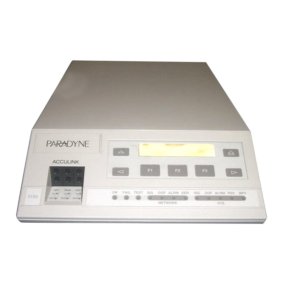
Information Guide and the COMSPHERE 3000 Series Carrier Installation Manual . ACCULINK EQPT 3150 Figure 3-1. Standalone CSU Front Panel Using the Front Panel The standalone CSU front panel of an LCD, a keypad, test jacks, and 12 LEDs. The... -
Page 25: Lcd
When a response is required, select from the options displayed directly above the Function keys (F1, F2, F3); make your choice by pressing the corresponding Function key. 3150-A2-GB21-80 Keypad The 7-button keypad navigate through the menu tree and select choices presented on the second line of the LCD. -
Page 26: Test Jacks
The twelve front panel LEDs are grouped into three sections to indicate the status of the: System Network interface character DTE interface Test Jacks section February 1998 Figure 3-5. CSU LEDs (Table 3-1) (Table 3-2) (Table 3-3) 3150-A2-GB21-80... - Page 27 Indicates whether an alarm condition exists on the received network signal. Yellow Indicates the Excessive Error Rate (EER) has been exceeded on the network interface. NOTE: This LED is only valid when ESF framing is being used. 3150-A2-GB21-80 Table 3-1 System LEDs Meaning ON : The CSU is operational and has power.
- Page 28 ON : At least one BPV was detected (and corrected) on the received T1 DTE interface signal during the sampling period. OFF : No BPVs were detected on the received T1 DTE interface signal during the sampling period. February 1998 3150-A2-GB21-80...
-
Page 29: Displaying Unit Identity
Test 2. From the Status screen, press the ID selection appears on the screen. 3. Select ID. Status: TStat 3150-A2-GB21-80 4. The following screens appear in the order listed each time you press the Front Cnfig key until the February 1998 Operation key. -
Page 30: Setting Customer Identification
LED name indicates the condition is ON, while an underscore indicates the condition is Off. 4. Use the onto the screen. Save February 1998 Front Panel Emulation). key until the Status: Perf TStat LED Display: _Test _NetSig keys to scroll LED names 3150-A2-GB21-80... -
Page 31: Changing Configuration Options
This set is determined by what is considered to be the second most common configuration used in the CSU market. Factory 2 options are read-only. 3150-A2-GB21-80 The configuration options are divided into functional groups. Appendix C contains a list of the configuration options and defaults. -
Page 32: Displaying/Editing Configuration Options
5. Press the appropriate Function key to choose another value. Use the scroll keys, if necessary. 6. Use the Save procedure to save your changes to the Active or Customer area. February 1998 Edit: NET Framing: ESF Next 3150-A2-GB21-80... -
Page 33: Configuring The Csu For Snmp Or Telnet Access
Customer 1, or Customer 2 area. Use the scroll keys, if necessary. Save Edit to: Activ Cust1 3150-A2-GB21-80 Configuring the CSU for SNMP or Telnet Access To configure the CSU for SNMP or Telnet access, Enable the SNMP agent or Telnet server within the DSU/CSU (see Appendix C, Options). -
Page 34: Setting The Ip Address
4. From the Edit screen, press the Mgmt selection appears on the screen. ASCII 5. Select Mgmt. 6. From the Mgmt Config screen, select Gen. February 1998 Scenarios). For CSUs using PPP, the key until the Edit: User Alarm Mgmt Mgmt Config: Trap 3150-A2-GB21-80... -
Page 35: Selecting The Link Layer Protocol
F3 (Save) to save the value. Otherwise, the original value will be retained. 010.155.111.222 Down 3150-A2-GB21-80 Selecting the Link Layer Protocol Two link layer protocols, Point-to-Point Protocol (PPP) and Serial Line Internet Protocol (SLIP), are supported for connection to an external SNMP manager, Telnet device, or network device (e.g., a router). -
Page 36: Specifying The Community Name(S) And Access Type(S)
Mgmt selection appears on the screen. 5. Select Mgmt. 6. From the Mgmt Config screen, select Gen. SLIP 7. Press F1 (Next) until the CommunityName1 configuration option appears. February 1998 key until the Edit: User Alarm Mgmt Mgmt Config: Trap 3150-A2-GB21-80... - Page 37 F1 (Up) or F2 (Down) to scroll through the valid numbers/characters for the text string. public Down 3150-A2-GB21-80 The F1 (Up) key scrolls through the ASCII character set in the following order: numbers (0 –9), lowercase letters (a–z), uppercase letters (A–Z), space character, ASCII symbols (ascending...
-
Page 38: Configuring Snmp Traps
Function key. Use the scroll keys, if necessary. key until the 3. Select Edit. 4. From the Edit screen, press the Mgmt selection appears on the screen. 5. Select Mgmt. February 1998 SNMP Trap: Next Enab Disab key until the Edit: User Alarm Mgmt 3150-A2-GB21-80... -
Page 39: Configuring A Destination For Snmp Traps
Function key. Use the scroll keys, if necessary. 3. Select Edit. 4. From the Edit screen, press the Mgmt selection appears on the screen. 3150-A2-GB21-80 5. Select Mgmt. 6. From the Mgmt Config screen, select Trap. 7. Press F1 (Next) until the Trapn IP Address configuration option appears. -
Page 40: Establishing Access Security On A Port
/. Press F3 (Save) to save the password. February 1998 Establishing Access Port) the password itself is set. Unless you key until Control: Reset CID Passwd keys to position the cursor moves the cursor to the Passwd: xxxxxxxx Down Save Passwd: xxxxxxxx Down Save 3150-A2-GB21-80... -
Page 41: Entering A Password To Gain Access
CSU ends the session. 3. Press F3 (Done) to indicate you are done entering the password. If you enter an invalid password, the message Invalid Password appears. 3150-A2-GB21-80 Acquiring/Releasing the User Interface You can access the user interface from either the front panel, the COM port, the MODEM port (for standalone CSUs), or the SDCP (for carrier-mounted CSUs). -
Page 42: Enabling/Disabling The Front Panel
3. Select Edit. 4. Select User. 5. Press F1 (Next) until the FP Access configuration option appears. 6. Press F2 to enable the front panel or F3 to disable the front panel. February 1998 NOTE FP Access: Next Enab Disab 3150-A2-GB21-80... -
Page 43: Using The Integral Modem In Standalone Csus
CSUs because the integral modem is not available for carrier-mounted CSUs. 3150-A2-GB21-80 To enter or change numbers in the phone directories, 1. From the top-level menu screen, press the until the Ctrl selection appears on the screen. - Page 44 B. Then, it must immediately follow the B. To be valid, this must be the first character in the string. February 1998 for the set of valid characters and Example: P9W8135551212 1: xxxxxxxxxxxxxxxxx Down Save Restrictions — — — — — — 3150-A2-GB21-80...
-
Page 45: Initiating A Call For Front Panel Pass-Through Operation
4. From the Call Setup screen, select Pass. Call Setup: Pass Dial 3150-A2-GB21-80 5. From the Pass Directory screen, press F1 (Up) to display the next higher numbered directory or press F2 (Down) to select the next lower numbered directory. -
Page 46: Disconnecting The Modem Connection
3150 CSU). Pressing and holding the keys simultaneously (when a pass-through connection is established to a remote device other than a 3150 CSU). 3-24 To disconnect an established modem connection using the Disconnect command, 1. From the top-level menu screen, press the until the Ctrl selection appears on the screen. -
Page 47: Enabling The Communication Port For Carrier-Mounted Csus
User is displayed. Select User. Edit: 5. Press F1 (Next) until the Com Port configuration option appears. 3150-A2-GB21-80 6. Select Enab to enable the COM port for the carrier-mounted CSU. The carrier COM port provides the following functionality: If configured for ASCII, only one ASCII device may be used for the carrier. - Page 48 0x01 0x02 0x03 0x04 0x05 0x06 0x07 0x08 0x09 LF or NL 0x0A 0x0B FF or NP 0x0C 0x0D 0x0E 0x0F 0x10 0x11 0x12 0x13 0x14 0x15 0x16 0x17 0x18 0x19 0x1A 0x1B 0x1C 0x1D 0x1E 0x1F February 1998 3150-A2-GB21-80...
-
Page 49: Deactivating The Alarm Relay For Carrier-Mounted Csus
3. From the Control screen, select ACO. Control: 4. The Command Complete screen appears. Alarm Cut-Off: Command Complete 3150-A2-GB21-80 Resetting the CSU Use the Reset command to perform a power-on reset of the CSU. To reset the CSU, 1. From the top-level menu screen, press the until the Ctrl selection appears on the screen. -
Page 50: User Interface Access Security For Standalone Csus
You can only reach the screen that controls security access using the front panel. 3150-A2-GB21-80 Changing User Interface Access Security To change user interface access security, 1. Press the key two times from the top-level screen. -
Page 51: Maintenance
These features ensure that your CSU is giving you optimum performance in your network. 3150-A2-GB21-80 Maintenance ............ -
Page 52: Self-Test Health
2. From the Status screen, select STest. 3. View the results of the last power-up self-test. If no problems were found during power-up, the following message appears. Cnfig Table 4-1 Self-Test Health Messages Description February 1998 Status: DevHS STest Perf STest Health: Passed 3150-A2-GB21-80... -
Page 53: Device Health And Status
A Yellow Alarm signal is being received by the network interface. Yellow at DTE A Yellow Alarm signal is being received by the DTE interface. 3150-A2-GB21-80 3. Use the scroll keys, if necessary, to scroll additional device health and status messages onto the LCD. -
Page 54: Performance Reports
CSU. The procedure for displaying Telco registers is similar to this example. To display User Network Interface (User) performance, 1. From the top-level menu screen, select Stat. 2. From the Status screen, select Perf. February 1998 NOTE Status: DevHS STest Perf 3150-A2-GB21-80... - Page 55 User registers for the 24-hour total interval appear. User 24 Hour: VldIntvl = xx 3150-A2-GB21-80 7. When you press F3 from the User Registers screen, the interval screen appears. Use this screen to choose the specific 15-minute interval.
- Page 56 The total number of errored seconds for the previous 24 hours. The total number of unavailable seconds for the previous 24 hours. The total number of severely errored seconds for the previous 24 hours. February 1998 Clear Prf Regs: User Totals Description 3150-A2-GB21-80...
- Page 57 F – A Frame Synchronization Bit Error has been detected. V – A Bipolar Violation has been detected. If none of these events occurred during the interval, StEvnt=none will be displayed. 3150-A2-GB21-80 Table 4-3 (2 of 2) Performance Registers Totals Description The total number of bursty errored seconds for the previous 24 hours.
-
Page 58: Alarms
Also, an alarm clear message is only sent when there are no other alarms active. For information about alarm configuration options, refer to the Alarm Configuration Options Appendix C, Configuration Options. For troubleshooting information, refer to the Troubleshooting section on page 4-10. February 1998 section in 3150-A2-GB21-80... -
Page 59: Snmp Traps
These traps are set by the Link Trap configuration option. The communications interfaces for which these traps can be generated are specified by the Trap I/F configuration option. Table 4-5 defines traps for each interface. 3150-A2-GB21-80 Enterprise-Specific Trap Definitions Trap Value enterpriseSelfTestFail(2) enterpriseDeviceFail(3) enterpriseTestStart(5) -
Page 60: Troubleshooting
3. Contact your facility provider. 1. Check the status of the DTE. 2. Check that the DTE cable is securely attached at both ends. 1. Check the status of the upstream device(s). 2. Contact your facility provider. February 1998 Solutions 3150-A2-GB21-80... - Page 61 The modem is receiving a busy signal. No Answer Tone The remote end does not answer within 45 seconds. Modem In Use The modem is in use. 3150-A2-GB21-80 Table 4-6 (2 of 2) Troubleshooting Check the DTE. Contact your facility provider.
-
Page 62: Test Jacks
Mon Jack: EQPT Mon Jack: NET (Selectable) LINE INTERNAL CIRCUITRY RECEIVER (Selectable) Mon Jack: EQPT Mon Jack: NET Figure 4-2. Test Jack Block Diagram February 1998 key until key until Control: Passwd Mon Mon Jack: EQPT EQPT LINE NETWORK RECEIVER 496-14875 3150-A2-GB21-80... - Page 63 EQPT Out (Equipment Out) MON In (Monitor In) MON Out (Monitor Out) 3150-A2-GB21-80 Table 4-7 Test Jack Functions Function A break-in test jack that allows a signal to be inserted toward the network by external test equipment. A break-in test jack that interrupts the signal coming from the network and allows it to be terminated by the external test equipment.
-
Page 64: Test Commands
During this time, Sending appears on Line 2 of the LCD, followed by Command Complete when 10 seconds have elapsed. You can press any function key to restore the Rem Loopback screen without affecting transmission of the loopback code. February 1998 Ptrns 3150-A2-GB21-80... -
Page 65: Local Loopback Tests
Table 4-8 are identified by YES. Table 4-8 Valid Loopback Combinations 3150-A2-GB21-80 Starting a Line Loopback The Line Loopback command (LLB) loops the received signal on the network interface (NI) back to the network without change. To perform a Line loopback, Options). -
Page 66: Starting A Payload Loopback
Already Active message appears. If an invalid combination of loopbacks is in progress, the error message Table 4-8 Invld Test Combo appears (see valid loopback test combinations). February 1998 Test: Rlpbk Lpbk Ptrns key until Loopback: Table 4-8 3150-A2-GB21-80... -
Page 67: Starting A Repeater Loopback
Active message appears. If an invalid combination of loopbacks is in progress, the error message Invld Test Combo appears (see loopback test combinations). 3150-A2-GB21-80 Aborting Loopbacks The Abort Loopback command stops all loopback tests or any selected loopback test currently active on the CSU. -
Page 68: Test Patterns
If the maximum of 99999 is exceeded, OvrFlw appears instead of the count. If the receiver loses synchronization while the monitor is active, No Sync appears. February 1998 Send: Name Test Started Test: Rlpbk Lpbk Ptrns Patterns: Abort Send 3150-A2-GB21-80... -
Page 69: Lamp Test
Use the TStat branch to view the test status to determine if the abort was successful. 3150-A2-GB21-80 Lamp Test Use the Lamp Test commands to start and stop a test of the CSU front panel LCD and LEDs. -
Page 70: Aborting A Lamp Test
LCD is alternating the Lamp test screens, press any Function key. Otherwise, follow Steps 1 through 3 for starting a Lamp test. 2. From the Lamp Test screen, select Abort. February 1998 Lamp Test: Abort Start Lamp Test: Abort Start 3150-A2-GB21-80... -
Page 71: Displaying Csu Test Status
DLB Test, Extrn The DTE port is being held in DTE loopback by the external contact. Lamp Test Active The Lamp test is currently active. 3150-A2-GB21-80 3. Select TStat. The Test Status screen appears showing you what key until the tests are active for the CSU. -
Page 72: Front Panel Menu
Stat DevHS STest Perf TStat LED Telco User Rlpbk 24Tot Intvl LLBUP LLBDN Abort For Carrier-Mounted CSUs only For Standalone CSUs only 3150-A2-GB21-80 Front Panel Menu CSU ESF Test Cnfig Lamp Lpbk Ptrns Abort Send QRSS 1in8 Load Edit Area From:... -
Page 73: Technical Specifications
Table B-1. The technical specifications for carrier-mounted CSUs are listed in Appendix B of the ACCULINK 3151 CSU and 3161 DSU/CSU General Information Guide. Model 3150 CSU Technical Specifications Specifications POWER REQUIREMENTS Typical: AC Power Module Optional: +24 Vdc –... - Page 74 ACCULINK 315x CSU Model 3150 CSU Technical Specifications Specifications LOOPBACKS Standard Additional APPROVALS MODEM INTERFACE Physical Interface Rate Integral Dial Modem PHYSICAL DIMENSIONS Height Width Depth WEIGHT ENVIRONMENT Operating Temperature Storage Temperature Relative Humidity Shock and Vibration Table B-1 (2 of 2) Criteria AT&T TR 54016, AT&T TR 62411, ANSI T1.403.1989...
-
Page 75: Configuration Options
(Table C-3). 3150-A2-GB21-80 Configuration Options ........... - Page 76 For ESF format, a yellow alarm is sent by continuously sending 8 ones followed by 8 zeros on the Facility Data Link (FDL). Enab – Transcodes the signal transmitted to the DTE. Disab – Disables transcoding. Table C-1 DTE Interface Configuration Options 399 —533 533 — 655 Prev February 1998 3150-A2-GB21-80...
- Page 77 Disab – Disables the FDL management link. NOTE: This configuration option is only available if the framing format is set to ESF. NOTE: If the local CSU’s FDL is enabled, the remote CSU’s FDL must also be enabled. 3150-A2-GB21-80 Table C-2 (1 of 3)
- Page 78 One – Sends a framed all ones signal to the network in case of an unrecoverable DTE signal. This complies with FCC Part 68 only. NetLp – Loops back the received network signal in case of an unrecoverable DTE signal. This complies with FCC Part 68 only. Table C-2 (2 of 3) February 1998 3150-A2-GB21-80...
- Page 79 Enab – When NET Framing is set to ESF, the CRC is sent to the DTE. When NET Framing is set to D4, all framing bits are sent to the DTE. Disab – Any framing or CRC bits that are in error are recalculated before being sent to the DTE. 3150-A2-GB21-80 Table C-2 (3 of 3)
- Page 80 Use the Function keys (Up or Down) to increment or decrement the digit. Up – Increments the test duration. Down – Decrements the test duration. Save – Stores the test duration. Table C-3 General Configuration Options February 1998 3150-A2-GB21-80...
- Page 81 Disab – Prevents dial-in access. Incoming calls to the CSU are not answered. NOTE: To enable Dial-In for carrier-mounted CSUs, the external device must be configured for automatic answer and the ComExtDev configuration option must be enabled. 3150-A2-GB21-80 A circular symbol ( ) identifies configuration options that are available on standalone CSUs only.
- Page 82 NOTE: Carrier Detect (CD) is used to detect that the external device’s connection is lost. Therefore, do not allow the CD lead to be forced on by the external device. NOTE: The external device should be strapped to ignore Data Terminal Ready (DTR). Table C-4 (2 of 8) User Interface Configuration Options Prev Prev February 1998 3150-A2-GB21-80...
- Page 83 NOTE: This configuration option is available on carrier-mounted CSUs only. NOTE: This configuration option is not available if the ComExtDev configuration option is set to AT or the communication port is disabled. 3150-A2-GB21-80 Table C-4 (3 of 8) User Interface Configuration Options...
- Page 84 Ext – Configures the communication port for external clocking. NOTE: This configuration option is not available if the Com Type configuration option is set to Async. C-10 Table C-4 (4 of 8) User Interface Configuration Options 0.8s 1.0s Prev February 1998 3150-A2-GB21-80...
- Page 85 CmDiscTm configuration option. Enab – The communication port disconnects after the period of inactivity specified by the CmDiscTm configuration option. Disab – The communication port does not disconnect due to inactivity. 3150-A2-GB21-80 Table C-4 (5 of 8) User Interface Configuration Options 19.2...
- Page 86 None Even Prev Modem Parity. Configures the parity for the modem port. None is the factory default. NOTE: This configuration option is available on standalone CSUs only. C-12 Table C-4 (6 of 8) User Interface Configuration Options February 1998 3150-A2-GB21-80...
- Page 87 Daisy – Configures the auxiliary port as an SNMP or Telnet port that is daisy chained to the communication port of an another 31xx Series device. NOTE: This configuration option is available on standalone CSUs only. 3150-A2-GB21-80 Table C-4 (7 of 8)
- Page 88 Use the Function keys (Up or Down) to increment or decrement the digit. Up – Increments the time delay. Down – Decrements the time delay. Save – Stores the time delay for use with inactivity disconnects. C-14 Table C-4 (8 of 8) User Interface Configuration Options February 1998 3150-A2-GB21-80...
- Page 89 NOTE: This configuration option is only available if SNMP traps are enabled and the integral modem or the carrier external communication port device is enabled and configured as an SNMP management link. 3150-A2-GB21-80 A triangular symbol ( ) identifies a configuration option that is available on carrier-mounted CSUs only.
- Page 90 NOTE: For carrier-mounted CSUs, this configuration option is only available if the communication port is enabled for an external device. C-16 Table C-5 (2 of 3) Alarm Configuration Options Prev Prev February 1998 3150-A2-GB21-80...
- Page 91 Alarm Indication Signal (AIS) received at either the network or DTE interface. Yellow alarm signal received at either the network or DTE interface. Excessive Error Rate (EER) detected at the network interface. NOTE: This configuration option is available on carrier-mounted CSUs only. 3150-A2-GB21-80 Table C-5 (3 of 3) Alarm Configuration Options...
- Page 92 A circular symbol ( ) identifies configuration options that are available on standalone CSUs only. A triangular symbol ( ) identifies configuration options that are available on carrier-mounted CSUs only. Table C-6 (1 of 6) Prev February 1998 NOTE 3150-A2-GB21-80...
- Page 93 Information Base (MIB). External SNMP managers must supply this name to access an object in the MIB. Edit – Allows you to edit or display the second community name. Clear – Allows you to clear the second community name. 3150-A2-GB21-80 Table C-6 (2 of 6)
- Page 94 000.000.000.000, the IP protocol creates a default subnet mask based on the class of the IP address (Class A: 255.000.000.000, Class B: 255.255.000.000, or Class C: 255.255.255.000). NOTE: This configuration option is not available on carrier-mounted CSUs if the communication port is disabled. C-20 Table C-6 (3 of 6) February 1998 3150-A2-GB21-80...
- Page 95 Edit – Allows you to edit or display the alternate IP address for the modem port. Clear – Allows you to clear the alternate IP address for the modem port. The IP address is set to 000.000.000.000. NOTE: This configuration option is available on standalone CSUs only. 3150-A2-GB21-80 Table C-6 (4 of 6)
- Page 96 000.000.000.000, the IP protocol creates a default subnet mask based on the class of the IP address (Class A: 255.000.000.000, Class B: 255.255.000.000, or Class C: 255.255.255.000). NOTE: This configuration option is available on standalone CSUs only. C-22 Table C-6 (5 of 6) February 1998 3150-A2-GB21-80...
- Page 97 FDL – The default network destination is FDL. This selection only appears if the FDL management link is enabled. NOTE: If the chosen default network link is disabled or down, data is discarded. Return to this menu and choose another default network. 3150-A2-GB21-80 Table C-6 (6 of 6)
- Page 98 Both – Sends trap messages for warmStart and authenticationFailure events to the currently configured trap manager(s). NOTE: This configuration option is not available if the SNMP Trap configuration option (in the Options section on page C-15) is disabled. C-24 Table C-7 (1 of 2) Prev Prev February 1998 Alarm Configuration 3150-A2-GB21-80...
- Page 99 Both – Sends trap messages for linkUp and linkDown events occurring on both the network and DTE interface. NOTE: This configuration option is not available if the Link Trap configuration option is not configured to generate trap messages for linkUp or linkDown events. 3150-A2-GB21-80 Table C-7 (2 of 2)
-
Page 100: Configuration Worksheets
Enab, Disab BitStuff 62411, Part68, Disab KeepAlive AIS, One, NetLp Yellow Enab, Disab Circuit Ident Edit, Clear CRC PThru Enab, Disab General Options Value (Default in Bold) Tst Timeout Enab, Disab Tst Duration 1 –120 (Default = 10) February 1998 3150-A2-GB21-80... - Page 101 Modem Rate 7, 8 MChar Len None, Even, Odd MParity 1, 2 MStop Bits Enab, Disab LSpaceDisc 3150-A2-GB21-80 User Options Value (Default in Bold) Enab, Disab MoInActTm 1 –60 (Default = 5) MoDiscTm None, Mgmt, Daisy Aux Use 9.6, 14.4, 19.2, 38.4...
- Page 102 Trap I/F NET, DTE, Both NOTE A circular symbol ( ) identifies configuration options that are available on standalone CSUs only. A triangular symbol ( ) identifies configuration options that are available on carrier- mounted CSUs only. February 1998 3150-A2-GB21-80...
-
Page 103: Pin Assignments
Various other interconnecting cables are available. For cable feature numbers, refer to Appendix I, Equipment List. This appendix describes connector pin assignments and cables. 3150-A2-GB21-80 Pin Assignments T1 Network Interface The T1 network interface connector is an RJ48C, 8-position, unkeyed modular jack... - Page 104 ACCULINK 315x CSU Figure D-1. T1 Line Interface Cable, RJ48C-to-RJ48C Figure D-2. T1 Line Interface Cable, RJ48C-to-DA15P February 1998 3150-A2-GB21-80...
- Page 105 DTE vendor. It is made of shielded twisted-pair wires (22 AWG). The cable connector is a DB15-type plug connector. Be sure to connect the shield ground only at the CSU end to prevent ground loops. 3150-A2-GB21-80 Receiver Tip from DTE DTE Interface Receiver Ring from DTE...
- Page 106 The integral modem VF cable is a 14.5-foot, 26 AWG, 4-conductor keyed cable with an RJ11C-like plug connector (Figure D-4). This cable is supplied with your standalone CSU. Integral Modem Port Connector Signal VF Ring VF Tip Figure D-4. Integral Modem Cable February 1998 Table D-3 Pin Number 3150-A2-GB21-80...
- Page 107 Signal DTE Transmit Clock DTE Receive Data Signal Ground DTE Transmit Data DTE Receive Clock 3150-A2-GB21-80 For daisy-chaining an AUX port to a COM port, a 25-pin-to-8-pin, cable is required and the appropriate configuration options (Com Use and Aux Use) must be set to Daisy.
- Page 108 Figure D-5 negotiated for the link layer. Table D-5 COM Port Connector Direction From CSU From CSU — To CSU To CSU From CSU To CSU From CSU February 1998 NOTE Pin Number 3150-A2-GB21-80...
- Page 109 Pin Assignments Figure D-5. COM Port-to-PC Cable Figure D-6. COM Port-to-Terminal/Printer Cable 3150-A2-GB21-80 February 1998...
- Page 110 COM port. Pin 14 Pin 1 Pin 13 Pin 25 Chassis Ground Signal Ground CD (RLSD) Plug Plug Figure D-7. Serial Crossover Cable February 1998 Pin 1 Pin 14 Pin 25 Pin 13 Chassis Ground Signal Ground CD (RLSD) 497-15180a 3150-A2-GB21-80...
- Page 111 – 48 Vdc B +24 Vdc +24 Vdc Return Chassis Ground 3150-A2-GB21-80 Optional DC Power Cable The power cable is a 14.5-foot, 18 AWG stranded cable. The connector is terminated at one end with a 6-position connector. The other end of the cable is terminated with a bare wire that should be connected to a dc power source.
-
Page 112: Snmp Mib Objects
T1 DTE interfaces on the CSU. 3150-A2-GB21-80 SNMP MIB Objects ............ -
Page 113: Mib Ii (Rfc)
System Group – “sysObjectID” Object (system 2) This object provides the authoritative identification of the network management subsystem contained in the unit. This object displays the following object identifier: 3150 [Company OID].1.14.2.1.1 3151 [Company OID].1.14.2.1.2 System group –”sysContact” Object (system 4) This object provides a textual identification of the contact person for this managed node. -
Page 114: Interface Group, Mib Ii
1 – Net T1 2 – DTE T1 3 – COM port 4 – Modem port 3150-A2-GB21-80 5 – Auxiliary RS-232 port The supported ifIndexes for the 3150 CSU are: Net T1 DTE T1 COM port Modem port Auxiliary RS-232 port... - Page 115 Otherwise, the interface is always up(1) when the modem is connected and down(2) when the modem is not connected. The interface is never in the testing(3) state. February 1998 3150-A2-GB21-80...
-
Page 116: Ip Group, Mib Ii
(ifEntry 18) ifOutDiscards (ifEntry 19) ifOutErrors (ifEntry 20) ifOutQLen (ifEntry 21) 3150-A2-GB21-80 IP Group, MIB II The IP Group objects are supported by the CSU for all data paths which currently are configured to carry IP data to or from the CSU, including the MODEM, COM, AUX, carrier SNMP bus, and FDL. - Page 117 MIB II. Route entries with an unrecognized ipRouteIfIndex value should not be deleted. When setting this object via SNMP, the ipRouteIfIndex value can only assume an appropriate value of ifIndex defined for the particular device type. February 1998 3150-A2-GB21-80...
-
Page 118: Tcp Group, Mib Ii
SNMP. ICMP Group, MIB II The ICMP Group objects are fully supported by the CSU. 3150-A2-GB21-80 TCP Group, MIB II The TCP Group objects are fully supported by the DSU/CSU, with the exception of the tcpConnState object, which will be read-only. -
Page 119: Ds1/E1 Mib (Rfc)
(i.e., setting to dsx1SendNoCode). dsx1SendOtherTestPattern(8) – Specifies that the network interface is sending a 1-in-8 test pattern. The pattern is sent until the test is halted (i.e., setting to dsx1SendNoCode). February 1998 3150-A2-GB21-80... - Page 120 – The near end of the T1 interface is in a loopback state. dsx1Other Failure(4096) – An Excessive Error Rate (EER) has been detected on the network interface. 3150-A2-GB21-80 Near End Group – “dsx1SignalMode” Object (dsx1ConfigEntry 11) This object specifies whether Robbed Bit Signaling (RBS) is being used.
- Page 121 DS1 Far End Total These tables are not supported for either the network or DTE interface. DS1 Fractional Group, DS1/E1 MIB The DS1 Fractional Group consists of the DS1 fractional table. This table (dsx1FracTable) is not supported by the CSU. February 1998 3150-A2-GB21-80...
-
Page 122: Rs-232-Like Mib (Rfc)
(rs232 1) This object contains the number of ports in the RS-232-like general port table. This number is 3 for the 3150 CSU and 1 for the 3151 CSU when the COM port is enabled. General Port Table, RS-232-like MIB The general port table contains general configuration objects for the RS-232-like interfaces. - Page 123 “rs232SyncPortClockSource” (rs232SyncPortEntry 2) This object specifies the clock source for the port. Only the following values are supported by the CSU. internal(1) – The port uses an internal clock. external(2) – The port uses an external clock. February 1998 3150-A2-GB21-80...
-
Page 124: Generic-Interface Mib Extensions (Rfc)
This object contains the result of the most recently requested test. Only the following values are supported by the CSU. none(1) – No test currently active. 3150-A2-GB21-80 inProgress(3) – A test is currently in progress. notSupported(4) – The requested test is not supported. -
Page 125: Enterprise Mib
Select the interval number with dsx1IntervalNumber. Read the value in the following objects for NET T1 dsx1IntervalES dsx1IntervalUAS dsx1IntervalSES dsx1IntervalBES dsx1ValidIntervals Read the value in the following objects for NET T1 dsx1ValidIntervals dsx1TotalES dsx1TotalUAS dsx1TotalSES dsx1TotalBES February 1998 3150-A2-GB21-80... - Page 126 Test–>Ptrns–>Abort–>Send–>NET Test–>Ptrns–>Send–>1in8 Test–>Ptrns–>Abort–>Send–>NET Test–>Ptrns–>Mon–>QRSS–>NET Test–>Ptrns–>Abort–>Mon–>NET Cnfig–>Load Cnfig–>Save Cnfig–>Activ–>Edit–>DTE–>DTE Framing 3150-A2-GB21-80 Table E-1 (2 of 3) SNMP MIB Object Read: dsx1LineLoop from dsx1LoopbackConfig for Net T1 dsx1PayloadLoop from dsx1LoopbackConfig for Net T1 dsx1PayloadLoop from dsx1LoopbackConfig for DTE T1 dsx1LineLoop from dsx1LoopbackConfig for DTE T1...
- Page 127 Set/Display dsx1Fdl for NET T1 to dsx1Ansi–T1–403 or dsx1Att–54016 or dsx1other Set/Display rs232PortInSpeed or rs232PortOutSpeed for COM, AUX, or MODEM port Set/Display rs232AyncPortBits for COM or MODEM port Set/Display rs232AyncPortParity for COM or MODEM port Set/Display rs232AyncPortStopBits for COM or MODEM port February 1998 3150-A2-GB21-80...
-
Page 128: Ip Network Addressing Scenarios
SLIP connection) as a gateway to the subnet(s). In all instances, the addressing scheme presented works for both the LAN and the direct connections. 3150-A2-GB21-80 Although routing table entries are maintained automatically by 31xx Series devices, without the need for user configuration, only a maximum of 100 routes is supported for a given device. - Page 129 FF.FF.FF.00. A static route is set in the NMS host to subnet 135.18.1.0. 135.18.1.2 135.18.1.3 135.18.1.4 135.18.1.5 Figure F-1. Daisy-Chained Standalone at the Central Site ETHERNET 135.18.40.1 NETWORK ADAPTER SUBNET 135.18.1.0 135.18.1.7 135.18.1.6 February 1998 SUBNET 135.18.40.0 AUX/COM IP ADDRESS: 135.18.40.2 135.18.1.1 135.18.1.1 496-14645-03 3150-A2-GB21-80...
- Page 130 FF.FF.FF.00. A static route still must be set in the NMS host to subnet 135.18.2.0. 135.18.2.17 135.18.2.18 Figure F-2. Local Carrier with Remote Standalone 3150-A2-GB21-80 ETHERNET 135.18.40.1 NETWORK ADAPTER COM IP ADDRESS: 135.18.40.3 SUBNET 135.18.2.0...
- Page 131 NMS host for each subnet: 135.18.4.0, 135.18.6.0, 135.18.20.0. 135.18.6.22 135.18.6.34 SUBNET 135.18.6.0 ETHERNET 135.18.40.1 SUBNET 135.18.40.0 Figure F-3. Local Carrier Connection to Remote Carriers 135.18.20.23 135.18.20.45 SUBNET 135.18.20.0 ADAPTER COM IP ADDRESS: 135.18.40.4 SUBNET 135.18.4.0 February 1998 3150-A2-GB21-80...
- Page 132 NMS host (135.18.0.0). 135.19.6.22 135.19.6.34 ETHERNET ADAPTER 135.18.40.1 SUBNET 135.18.40.0 Figure F-4. Local Carrier Connected to Remote Carriers – an Alternative 3150-A2-GB21-80 135.19.20.23 135.19.20.45 COM IP ADDRESS: 135.18.40.4 SUBNET MASK: FF:FF:00:00 SUBNET 135.19.0.0...
- Page 133 SUBNET 135.18.23.0 135.18.23.2 COM IP ADDRESS: 135.140.22.95 ADAPTER 135.140.22.79 ETHERNET SUBNET 135.140.22.0 Figure F-5. Multiple COM Ports Connected to Different NMSs. SUBNET 135.18.34.0 135.18.34.2 COM IP ADDRESS: 135.18.40.5 ADAPTER ETHERNET SUBNET 135.18.40.0 February 1998 135.18.40.1 496-14649-02 3150-A2-GB21-80...
-
Page 134: Front Panel Emulation
ACCULINK 3151 CSU and 3161 DSU/CSU General Information Guide. 3150-A2-GB21-80 Front Panel Emulation .......... -
Page 135: Starting Front Panel Emulation
PC. NOTE When using Front Panel Emulation, no LEDs are shown on the PC’s screen; you must use the Stat command procedure to get LED information (see the Displaying LED Conditions section in Chapter 3, Operation ). February 1998 3150-A2-GB21-80... -
Page 136: Async Terminal Operation
Telnet access. 3150-A2-GB21-80 ............ - Page 137 Ctrl-a to move from the Screen area to the Screen Function Keys area MAIN MENU Status Test Configuration Control Figure H-1. Main Menu Screen February 1998 Entering a section on page H-12.) (Figure H-1), press Ctrl-a (control key (Figure H-1), and then select Exit. Model: 31xx Exit 3150-A2-GB21-80...
-
Page 138: Menu Organization
System and Display Test Status LEDs Performance Identity Statistics Network Communication Front Port Panel 3150-A2-GB21-80 cases, provide a more direct access to an option or function. Figure H-2 terminal menu tree. Main Test Configuration Call Directories Call Customer ID Setup... - Page 139 Moves the cursor down one field within a column on the same screen. Moves the cursor back one character to the right. Moves the cursor back one character to the left. Redraws the screen display. Accepts entry. NOTE 3150-A2-GB21-80...
- Page 140 Î Î Î Î Î Î Î Î Î Î Î Î Î Î Î Î Î Î Î Î Î Î Î Î Î Figure H-3. Customer Identification Screen 3150-A2-GB21-80 2. From the Control screen, select Customer ID. The Customer ID screen appears 3.
- Page 141 The screen shows a snapshot of the LEDs every 5 seconds. LEDs that are illuminated are displayed by inverse video. Select Refresh to update the screen. DISPLAY LEDs GENERAL NETWORK Fail Test February 1998 (Figure H-4). Model: 31xx MainMenu Exit 3150-A2-GB21-80...
- Page 142 Î Î Î Î Î Î Î Î Î Î Î Î Î Î Î Î Î Î Î Î Î Î Î Î Î Î Î Î Î Î Î Î Î Î Î Î Î Î Î Î Î Î Î Î Î Î Î Î Î Î 3150-A2-GB21-80 Displaying or Editing Configuration Options To display or edit configuration options, 1.
- Page 143 Î Î Î Î Î Î Î Î Î Î Î Î Î Î Î Î Î Î Î Î Î Î Î Î Î Figure H-6. Configuration Edit/Display Screen CONFIGURATION EDIT/DISPLAY Network General Options User Interface Alarms & Traps Management and Communication MainMenu February 1998 Model: 31xx Exit 3150-A2-GB21-80...
- Page 144 Î Î Î Î Î Î Î Î Î Î Î Î Î Î Î Î Î Î Î Î Î Î Î Î Î Î Î Î Î Î Î Î Î Î Î Î Î Î Î Î Î Î Î Î Î Î Î Î Î Î 3150-A2-GB21-80 Save edit changes to the Current area when you want those changes to take effect immediately.
- Page 145 Data Rate (Kbps): Character Length: Parity: None Stop Bits: Ignore Control Leads: Disable Password Required: Enable Inactivity Timeout: Enable Disconnect Time (Minutes): Figure H-8. Enabling a Password February 1998 H-8). Setting a Password. Model: 31xx Enable Password MainMenu Exit 3150-A2-GB21-80...
- Page 146 Î Î Î Î Î Î Î Î Î Î Î Î Î Î Î Î Î Î Î Î Î Î Î Î Î Î Î Î Î Î Î Î Î Î Î Î Î Î Î Î Î Î Î Î Î Î Î Î Î Î 3150-A2-GB21-80 This screen is used to add a new password or modify an existing password.
- Page 147 If an invalid password is entered three consecutive times, the message User Interface Idle appears, Telnet sessions are closed, dial-in connections are disconnected, and an SNMP trap is generated. LOGIN Enter Password Figure H-10. Entering a Password February 1998 Model: 31xx Enter Password Exit 3150-A2-GB21-80...
- Page 148 DTE Interface Options Line Framing Format Line Coding Format Line Equalization DTE LB on External Contact Send AIS on Network Failure Transcode Yellow Alarm to DTE 3150-A2-GB21-80 Front Panel Value (Default in Bold) Equivalent NET Framing D4, ESF NET Coding AMI, B8ZS 0.0, –7.5, –15, –22.5...
- Page 149 Com Port Enable, Disable ComExtDev Disable, AT, Other Dial-In Enable, Disable ComConnPrefix Text Field , Clear ComConnected Text Field , Clear Text Field , Clear ComEscapeSeq ComEscDel None, 0.2, 0.4, 0.6, 0.8, 1.0 ComDisconnect Text Field , Clear February 1998 3150-A2-GB21-80...
- Page 150 ASCII Alarm Messages Alarm & Trap Dial-Out Trap Disconnect Call Retry Dial Out Delay Time (Min) Alternate Dial-Out Directory Excessive Error Rate Threshold System Alarm Relay 3150-A2-GB21-80 Front Panel Value (Default in Bold) Equivalent TnSession Enable, Disable TnPaswd Enable, Disable...
- Page 151 Aux NetMask Text Field , Clear IPBusMast Enable,Disable Front Panel Value (Default in Bold) Equivalent SNMP Mgt Enable, Disable CommunityName1 Text Field , Clear Access 1 Read, R/W CommunityName2 Text Field , Clear Access 2 Read, R/W February 1998 3150-A2-GB21-80...
- Page 152 Number of Trap Managers NMS n IP Address NMS Manager n Destination General Traps Enterprise Specific Traps Link Traps Link Trap Interfaces 3150-A2-GB21-80 Front Panel Value (Default in Bold) Equivalent NMS Valid Enable, Disable Num Sec Mgrs 1, 2, 3, 4, 5, 6, 7, 8, 9, 10...
-
Page 153: Equipment List
Model 3150 CSU T1 Line Interface Cable, RJ48C-to-RJ48C T1 Line Interface Cable, RJ48C-to-DA15P COM Port-to-PC Cable, 8-pin modular to DB9S COM Port-to-Terminal/Printer Cable, 8-pin modular to DB25P DC Power Cable 115 Vac Power Module Front Panel Emulation Software Wall-Mount /Rack-Mount Adapter... -
Page 154: Glossary
AUX port Auxiliary Backplane bandwidth 3150-A2-GB21-80 Glossary A product family and a registered trademark. Alarm Cut-off command. A command for carrier-mounted CSUs that forces a deactivation of the alarm relay on the 3000 Series Carrier. Active configuration area. The configuration option set that is currently active for the device. - Page 155 Cyclic Redundancy Check. A mathematical method of confirming the integrity of received digital data. CRC using six check bits. Canadian Standards Association. Channel Service Unit. Protects the T1 line from damage and regenerates the T1 signal. Control branch of the CSU menu tree. Clear-to-Send. V.24 circuit 106. February 1998 3150-A2-GB21-80...
- Page 156 DSX-1 DS1/E1 MIB DTE interface DTMF 3150-A2-GB21-80 Customer 1 configuration area. The first of two sets of customer-defined configuration options. Customer 2 configuration area. The second of two sets of customer-defined configuration options. Connecting the COM port of one CSU to the AUX port of another CSU to provide SNMP connectivity.
- Page 157 Hertz. A unit of frequency that equals one cycle per second. Internet Control Management Protocol. The protocol that enables in-band control, diagnostic, and error messages to be passed between nodes in an IP internetwork. Identity branch of the CSU menu tree. A shared boundary between functional units. February 1998 3150-A2-GB21-80...
- Page 158 (SNMP) Mbps menu tree MIB II 3150-A2-GB21-80 The worldwide interconnected collection of networks that predominantly use the TCP/IP protocol. An interconnected collection of networks (also called an internet). Internet Protocol address. The address used by the SNMP manager to access the device.
- Page 159 Quasi-Random Signal Source Test. A test pattern simulating a random pattern of digital ones and zeros used to simulate normal transmission. Random-access memory. Read/write memory that is volatile and loses its contents when power is removed. February 1998 3150-A2-GB21-80...
- Page 160 StEvnt subnet subnet mask TCP/IP Telnet 3150-A2-GB21-80 A part of the device’s memory that holds stored values. Release branch of the CSU menu tree. A reinitialization of the CSU that occurs at power-up or in response to a reset command.
- Page 161 An outgoing signal transmitted when a DS1 terminal has determined that it has lost the incoming signal. A test pattern consisting of a one (1) followed by seven zeros (on the network only). A rack-mounted device containing 17 slots in which to place circuit cards. February 1998 3150-A2-GB21-80...
- Page 162 Self-Test Health message, 4-2 BES (Bursty Errored Seconds) report, 4-7 BPV (Bipolar Violation) condition front panel LED indication, 3-6 Performance Report message, 4-7 troubleshooting, 4-11 3150-A2-GB21-80 Index cabling equipment list, I-1 examples, 2-7 pin assignments, D-1–D-10 CID (Customer Identification) branch...
- Page 163 A-1 indicators. See LEDs, front panel integral modem, D IP (Internet Protocol) addressing configuration option, C-20, C-22 example of use, F-1–F-6 procedure for configuring, 3-12–3-13, 3-17 keypad operation, 3-3–3-4 physical description, 1-3, 3-2 February 1998 3150-A2-GB21-80...
- Page 164 Performance Report message, 4-7 Self-Test Health message, 4-2 troubleshooting, 4-10 Lpbk (Local Loopback) branch example of use, 4-15–4-17 in the menu tree, A-1 3150-A2-GB21-80 maintenance device health and status, 4-3–4-4 performance reporting, 4-4–4-7 power-up self-test, 2-8, 4-2 manager, SNMP, 1-2 menu tree, A-1–A-2...
- Page 165 A-1 status messages. See messages, status STest (Self-Test Health) branch example of use, 4-2 in the menu tree, A-1 StEvnt (Status Event) report, 4-7 straps. See configuration options subnet, 3-11, C-20, C-22, F-2 February 1998 3150-A2-GB21-80...
- Page 166 4-4–4-7 power-up self-test, 2-8, 4-2 TStat (Test Status) branch example of use, 4-21–4-22 in the menu tree, A-1 3150-A2-GB21-80 UAS (Unavailable Seconds) report, 4-6 User Configuration branch example of use, 3-12, 3-25–3-29 in the menu tree, A-1 option table, C-7–C-14 option worksheet, C-27 user interface, acquiring/releasing, 3-19–3-20...
Need help?
Do you have a question about the 3150 and is the answer not in the manual?
Questions and answers