Sign In
Upload
Download
Table of Contents
Contents
Add to my manuals
Delete from my manuals
Share
URL of this page:
HTML Link:
Bookmark this page
Add
Manual will be automatically added to "My Manuals"
Print this page
×
Bookmark added
×
Added to my manuals
Manuals
Brands
Edwards Manuals
Water Pump
iXM Series
Instruction manual
Edwards iXM Series Instruction Manual
Dry pump system
Hide thumbs
1
2
3
4
5
6
Table Of Contents
7
8
9
10
11
12
13
14
15
16
17
18
19
20
21
22
23
24
25
26
27
28
29
30
31
32
33
34
35
36
37
38
39
40
41
42
43
44
45
46
47
48
49
50
51
52
53
54
55
56
57
58
59
60
61
62
63
64
65
66
67
68
69
70
71
72
73
74
75
76
77
78
79
80
81
82
83
84
85
86
87
88
89
90
91
92
93
94
95
96
97
98
99
100
101
102
103
104
page
of
104
Go
/
104
Contents
Table of Contents
Bookmarks
Table of Contents
Table of Contents
1 Safety and Compliance
Definition of Warnings and Cautions
Safety Symbols
2 General Description
Overview
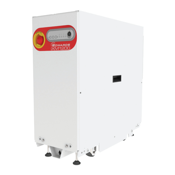
Figure 1 Front View of System
Applications
Figure 2 Controls/Connectors on the Rear of the System
Advanced Control and Monitoring
Green Mode
Figure 3 Applications
3 Technical Data
General Technical Data
Operating and Storage Conditions
Manufacturing Materials
Loading Data
Figure 4 Centre of Gravity and Levelling Foot Loads Ixm200
Figure 5 Centre of Gravity and Levelling Foot Loads Ixm600 and Ixm1200
Figure 6 Centre of Gravity and Levelling Foot Loads Ixm3000
Nitrogen Purge Data
Electrical Data
Cooling Water Data
Heater Data
Tracer Gas Analysis
4 Installation
Installation Safety
Unpack and Inspect
Position the System
Install the System
Figure 7 Reduce the Effective System Footprint
Lubrication
Connect the System
Connect to the Vacuum and Exhaust System
Figure 8 Reduce the Effective System Footprint Ixm3000
Connect the Pump Inlet
Figure 9 Connect the Pump Inlet (Ixm200 and Ixm3000)
Connect the Pump Exhaust
Connect to the Factory Extraction System (Optional)
Figure 10 Connect the Pump Inlet (Ixm600 and Ixm1200)
Connect the Nitrogen Supply
Connect to the Electrical Supply
Figure 11 Mains Input Supply Connector
Figure 12 Method for Connecting Phase Wires
Figure 13 Coding Pin Configuration
Figure 14 Mains Connector on Pump Bulkhead
Figure 15: Mains Input Supply Connector - Han® K 4/4
Figure 16 Protective Earth (PE) Connection
Connect an Additional RF Earth (Ground) (Optional)
Figure 17 Electrical Connector Locking Mechanism (Ixm200, Ixm600 and Ixm1200)
Figure 18 Electrical Connector Locking Mechanism
Connect to the Emergency Stop Circuit
Connect the Cooling Water Supply
Connect the Accessories
Install Additional Safety Equipment
5 Commission
Commission the System
Leak Test the System
Configure the System through a PDT
Pump Display Terminal
Figure 19 Pump Display Terminal
6 Operation
Start-Up
Start up through a Microtim
Start up through a PDT
Start up through the Front Panel Control
Restart the System after a Controlled Stop or Alarm Condition
Figure 20 Front Panel Controls
Restart the Pump after a Controlled Stop or Automatic Shut down
Shut down
Shut down Modes
Shut down through a Microtim
Shut down through a PDT
Shut down through the Front Panel Control
Controlled Stop
Gas Module Configuration
IXM Varimode Gas Module Adjustment Procedure
System Operating Temperature Configuration
7 Maintenance
Inspect the Connections, Pipelines, Cables and Fittings
8 Fault Finding
Warnings
LED Warning Indicators
PDT Warnings
Alarms
LED Alarm Indicators
PDT Alarms
Alarm Conditions
Unplanned Shut down and Alarms
Events
PDT Events
Inverter Warnings and Alarms
9 Decommissioning
Decommissioning Safety
Relocate the System for Decommissioning
Drain the Cooling Water for Decommissioning
Transportation
10 Storage
11 Disposal
12 Service
Return the Equipment or Components for Service
13 Accessories
Disconnect Box
Accessory Modules
Pump Display Terminal (PDT)
PDT Holster
PDT Extension Cable
Seismic Restraint Brackets
Nitrogen Flow Switch Assembly
Interface Modules
Microtim
EMS Modules
Igateway Modules
Exhaust Check Valve
Exhaust Extraction Cover Kit
Constant Flow Water Valves
Water Flow Monitor Assembly
Advertisement
Quick Links
1
Overview
2
General Technical Data
3
Electrical Data
Download this manual
edwardsvacuum.com
Dry Pump System
iXM
INSTRUCTION MANUAL
M56635880_D
Original instructions
Table of
Contents
Previous
Page
Next
Page
1
2
3
4
5
Advertisement
Table of Contents
Need help?
Do you have a question about the iXM Series and is the answer not in the manual?
Ask a question
Questions and answers
Related Manuals for Edwards iXM Series
Water Pump Edwards iXL120N Instruction Manual
Dry pump system (60 pages)
Water Pump Edwards iXL120 Instruction Manual
Dry pump system (60 pages)
Water Pump Edwards iXH100 Instruction Manual
Dry pumping systems (88 pages)
Water Pump Edwards iXM1200 Standard Instruction Manual
Dry pump system (104 pages)
Water Pump Edwards iXM1200 Customer special A Instruction Manual
Dry pump system (104 pages)
Water Pump Edwards iXM600 Standard Instruction Manual
Dry pump system (104 pages)
Water Pump Edwards iXM200 Instruction Manual
Dry pump system (104 pages)
Water Pump Edwards iXM1200 Xcede customer special A Instruction Manual
Dry pump system (104 pages)
Water Pump Edwards iXL600 Instruction Manual
Dry pump systems (70 pages)
Water Pump Edwards iXL1000 Instruction Manual
Dry pump systems (70 pages)
Water Pump Edwards iXL1000N Instruction Manual
Dry pump systems (70 pages)
Water Pump Edwards iH80 Instruction Manual
Ih series. dry pumping system (44 pages)
Water Pump Edwards iH600 Instruction Manual
Ih series. dry pumping system (44 pages)
Water Pump Edwards iH1800HTX Instruction Manual
Ih series. dry pumping system (44 pages)
Water Pump Edwards CDX1000 Instruction Manual
Chemical dry vacuum pumps and industrial dry vacuum pumps (82 pages)
Water Pump Edwards iF1800 Instruction Manual
Rapid loadlock dry pumping systems (126 pages)
This manual is also suitable for:
Ixm1200 standard
Ixm1200 customer special a
Ixm600 standard
Ixm200
Ixm1200 xcede standard
Ixm1200 xcede customer special a
...
Show all
Ixm600 xcede standard
Ixm200 xcede standard
Ixm200t
Ixm600t
Ixm1200t
Ixm3000 standard
Ixm3000 customer special a
Ixm3000 xcede
Table of Contents
Save PDF
Print
Rename the bookmark
Delete bookmark?
Delete from my manuals?
Login
Sign In
OR
Sign in with Facebook
Sign in with Google
Upload manual
Upload from disk
Upload from URL


Need help?
Do you have a question about the iXM Series and is the answer not in the manual?
Questions and answers