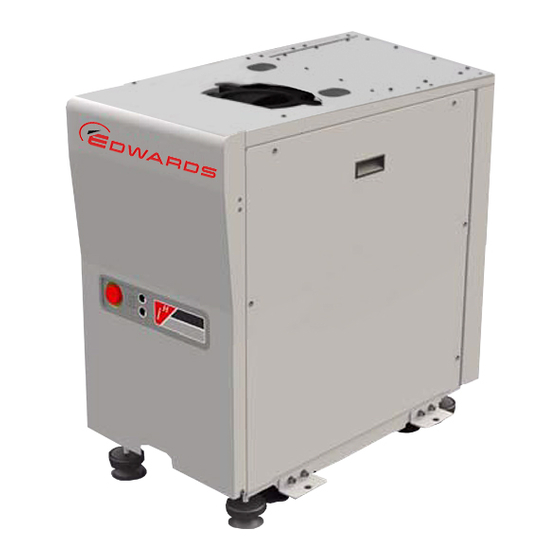
Edwards iH80 Instruction Manual

Edwards iH80 Instruction Manual

Ih series. dry pumping system
Table of Contents

Advertisement

Description
iH80
iH160
iH160HTX
iH600
iH1000
iH1800
iH1800HTX
iH1800NRV
iH1800NRV HTX
Where xxx is as follows:
460 V, 60 Hz, 3 phase
200/208 V, 50/60 Hz, 3 phase
380/415 V, 50 Hz, 3 phase
230 V, 60 Hz, 3 phase
Instruction Manual
iH Dry Pumping Systems
Item Number
A590-00-xxx
A590-10-xxx
A590-12-xxx
A590-20-xxx
A590-30-xxx
A590-40-xxx
A590-42-xxx
A590-50-xxx
A590-52-xxx
908
945
946
957
A590-00-880
Issue D Original

Advertisement

Table of Contents
loading

Summary of Contents for Edwards iH80

  • Page 1 A590-00-880 Issue D Original Instruction Manual iH Dry Pumping Systems Description Item Number iH80 A590-00-xxx iH160 A590-10-xxx iH160HTX A590-12-xxx iH600 A590-20-xxx iH1000 A590-30-xxx iH1800 A590-40-xxx iH1800HTX A590-42-xxx iH1800NRV A590-50-xxx iH1800NRV HTX A590-52-xxx Where xxx is as follows: 460 V, 60 Hz, 3 phase...
  • Page 2 NRV A590-50-xxx A590-52-xxx iH interface Module fitting kit A505-35-000 iH enclosure extraction fan (for iH80 and iH600 only) A505-39-000 iH Light Duty exhaust check valve A505-56-000 to which this declaration relates is in conformity with the following standard(s) or other...
  • Page 4 This page has been intentionally left blank.
  • Page 5: Table Of Contents

    3.8.1 Reconfigure the iH system for your electrical supply (if necessary) ..........19 3.8.2 Reconfigure the iH system for your electrical supply (iH80/600 only) ......... 19 3.8.3 Connect the electrical supply ..................21 Connect an additional RF earth (ground) (optional) ..............23 3.10...
  • Page 6 Accessories ....................... 37 Associated publications Publication title Publication number Vacuum Pump and Vacuum System Safety P300-20-000 Semiconductor Pumping Application Guide P411-00-090 Page ii © Edwards Limited 2008. All rights reserved. Edwards and the Edwards logo are trademarks of Edwards Limited.
  • Page 7: Introduction

    Introduction Scope and definitions This manual provides installation, operation and maintenance instructions for the Edwards iH dry pumping systems. You must use your pumping system as specified in this manual. Read this manual before you install and operate your pump. Important safety information is highlighted as WARNING and CAUTION instructions;...
  • Page 8: Applications

    If you use the iH system on an application for which it is not suitable (refer to Figure 1), you may invalidate your warranties. If in doubt, contact Edwards who will advise you as to the suitability of the iH system for any particular application. Figure 1 - iH applications chart...
  • Page 9: Description

    'in control'. Please refer to Figure Figure 2 - Priority of control 1. PDT 2. iM 3. iTIM 4. None in control Take Release © Edwards Limited 2008. All rights reserved. Page 3 Edwards and the Edwards logo are trademarks of Edwards Limited.
  • Page 10: The Controls/Connectors On Rear Of Pump

    8. LON module connection 4. Emergency stop fuse holder (F9) 9. Electrical supply connection 5. Tool interface module fuse holder (F8) Page 4 © Edwards Limited 2008. All rights reserved. Edwards and the Edwards logo are trademarks of Edwards Limited.
  • Page 11: Top View Of Pump

    6. Alarm LED (red) 2. Running LED (green) 7. Warning LED (amber) 3. Power OK LED (green) 4. Pump display terminal connection © Edwards Limited 2008. All rights reserved. Page 5 Edwards and the Edwards logo are trademarks of Edwards Limited.
  • Page 12 A590-00-880 Issue D This page has been intentionally left blank. Page 6 © Edwards Limited 2008. All rights reserved. Edwards and the Edwards logo are trademarks of Edwards Limited.
  • Page 13: Technical Data

    A590-00-880 Issue D Technical data General technical data Table 1 - Technical data iH80, iH600 and iH1000 Type Characteristics iH80 iH600 iH1000 Units General Dimensions (L (to exhaust enclosure) 776 (909) x 776 (909) x 776 (909) x x W x H (to inverter))
  • Page 14 µm Nitrogen flow rate Gas module pressure range bar gauge Pressure transducer accuracy +/-0.0041 at 0.4 +/-0.0041 at 0.4 bar gauge Page 8 © Edwards Limited 2008. All rights reserved. Edwards and the Edwards logo are trademarks of Edwards Limited.
  • Page 15: Electrical Data

    Full load (Amp) Motor rating (kW) HCMB Full load (Amp) Motor rating (kW) Max power input to both motors (kW) 8.96 © Edwards Limited 2008. All rights reserved. Page 9 Edwards and the Edwards logo are trademarks of Edwards Limited.
  • Page 16: Loading

    Table 4 - Centre of gravity and levelling foot loads (Refer to Figure 7) iH80 iH600 iH1000 iH160 iH1800 Centre of gravity Levelling loads Figure 7 - Centre of gravity and levelling foot loads Page 10 © Edwards Limited 2008. All rights reserved. Edwards and the Edwards logo are trademarks of Edwards Limited.
  • Page 17: Connections

    D type 15-way plug External emergency stop switch 24 V a.c. 5 A (load 700 mA inductive) Optional accessory. † HTX variants only. © Edwards Limited 2008. All rights reserved. Page 11 Edwards and the Edwards logo are trademarks of Edwards Limited.
  • Page 18: General Data

    Maximum operating altitude 2000 Pollution degree 2 (IEC 61010) With cooling water supply temperature of 20°C and flow rate of 3 l min Page 12 © Edwards Limited 2008. All rights reserved. Edwards and the Edwards logo are trademarks of Edwards Limited.
  • Page 19: Installation

    Edwards Publication Number P300-20-000 'Vacuum Pump and Vacuum System Safety'. Only Edwards engineers may install the dry pumping system. Users can be trained by Edwards to conduct the tasks described in this manual, contact your local service centre or Edwards for more information.
  • Page 20: Locate The Dry Pumping System

    6, item 1), if not use an iH Disconnect Box (refer to Section 7.3). Figure 8 - System arrangement to reduce effective footprint (if required) Page 14 © Edwards Limited 2008. All rights reserved. Edwards and the Edwards logo are trademarks of Edwards Limited.
  • Page 21: Lubrication

    Ensure that all components in the vacuum pipeline have a maximum pressure rating which is greater than the highest pressure that can be generated in your system. © Edwards Limited 2008. All rights reserved. Page 15 Edwards and the Edwards logo are trademarks of Edwards Limited.
  • Page 22: Connect The Ih1800Htx Exhaust Tms

    A590-00-880 Issue D Incorporate flexible pipelines in the vacuum pipeline to reduce the transmission of vibration and to prevent loading of coupling-joints. We recommend that you use Edwards braided flexible pipelines. The pipelines should be suitable for 110 °C. Adequately support vacuum/exhaust pipelines to prevent the transmission of stress to pipeline coupling-joints.
  • Page 23: Connect The Nitrogen Supply

    (limiting oxidant concentration). For further information please refer to Semiconductor Pumping Application Guide (Publication no. P411-00- 090) or contact Edwards: refer to the address page at the rear of this manual for details of your nearest Edwards company. © Edwards Limited 2008. All rights reserved.
  • Page 24: Gas Purges

    Do not connect voltages greater than 30 V a.c. or 60 V d.c. to the control/interface connections. If you do, the interface control will not provide protection against electric shock. Page 18 © Edwards Limited 2008. All rights reserved. Edwards and the Edwards logo are trademarks of Edwards Limited.
  • Page 25: Reconfigure The Ih System For Your Electrical Supply (If Necessary)

    (200 V to 230 V) and high voltage (380 V to 460 V) ranges. Contact your supplier or Edwards if you wish to use the iH system with a power supply in a different voltage range to that specified on the rating plate.
  • Page 26: Reconfigure The Ih System For Your Electrical Supply

    Figure 9 - Reconfigure the iH system for your electrical supply 1. Cover 4. Common cable 2. Screw (2 off) 5. Voltage select cable 3. Electrics box 6. Terminal block Page 20 © Edwards Limited 2008. All rights reserved. Edwards and the Edwards logo are trademarks of Edwards Limited.
  • Page 27: Connect The Electrical Supply

    Notes: 1. Edwards recommend that the electrical supply be connected to a suitable isolator, which is easily accessible for maintenance and clearly identified. 2. If you need further information on connecting the electrical supply, look it up on the Web using URL at the start of manual, or contact your supplier or Edwards for advice.
  • Page 28 (refer to Section 7.3). 7. On iH80, 160 and 600 systems, we recommend that you fit a second protective earth (ground) conductor to the protective earth (ground) stud on the Electrics Box (Figure 3, item 1) and connect the other end of this conductor to your factory earth (ground).
  • Page 29: Connect An Additional Rf Earth (Ground) (Optional)

    4, item 7 and Table 5). The emergency stop control must be compliant with IEC 60947-5-1 (This should be a red self latching mushroom push button on a yellow background.). © Edwards Limited 2008. All rights reserved. Page 23 Edwards and the Edwards logo are trademarks of Edwards Limited.
  • Page 30: Connect The Cooling-Water Hoses

    SEMI S2 requirements. The photohelic switch/gauge when fitted, allows monitoring for loss of extraction from the enclosure, thereby satisfying SEMI S2 requirements.Refer to the individual accessories manuals for information about installation. Page 24 © Edwards Limited 2008. All rights reserved. Edwards and the Edwards logo are trademarks of Edwards Limited.
  • Page 31: Commission The System

    (Figure 6, item 3) goes on. If the LED does not go on, contact Edwards or refer to the Web. 2. Switch on the cooling-water and nitrogen supplies. 3. Ensure that the exhaust-extraction system is not blocked (for example, that valves in the exhaust-extraction system are open).
  • Page 32: Install Additional Safety Equipment

    4.4) the iH system will shutdown automatically. You must ensure that your installation remains safe if the iH system shuts down automatically. Page 26 © Edwards Limited 2008. All rights reserved. Edwards and the Edwards logo are trademarks of Edwards Limited.
  • Page 33: Operation

    Running LED is illuminated. Control must be taken with the iTIM. The message 'iTIM IN CONTROL' will be displayed on the PDT if connected. © Edwards Limited 2008. All rights reserved. Page 27 Edwards and the Edwards logo are trademarks of Edwards Limited.
  • Page 34: Status Indicators

    If the pump is not going to be required for some time, switch off the electrical supply and the cooling-water supply. Page 28 © Edwards Limited 2008. All rights reserved. Edwards and the Edwards logo are trademarks of Edwards Limited.
  • Page 35: Automatic Shut-Down

    The decision on whether or not to shutdown the pump is left with the tool. If the iH system has an unplanned shutdown, ensure that the cause of the shutdown is identified and rectified before restarting. If you are in any doubt, please call a Edwards Service Engineer. Table 7 - Safety sensors...
  • Page 36: Emergency Stop

    If there is an SEM connected to your iH system, you are able to download configuration sets, which contain preset configuration values, for example setpoints. Contact Edwards or go to the Web for more details. Page 30 ©...
  • Page 37: Maintenance

    Particular caution should be exercised when working with hydrocarbons which may have been exposed to temperatures greater than 260 °C. Refer to Edwards Material Safety Data Sheets for detailed information. Ensure that the maintenance technician is familiar with the safety procedures which relate to the products pumped.
  • Page 38: Relocate The System For Maintenance

    The iH system may have overheated if it was misused, if it malfunctioned or if it was in a fire. Edwards Material Safety Data Sheets for fluorinated materials used in the pump are available on request: contact your supplier or Edwards.
  • Page 39: Cleaning The Pump

    Inspect the pump monthly and, if necessary, wipe the outside clean with a soft lint free cloth and a proprietary cleaning material based on demineralised water or isopropanol. General maintenance The following maintenance can be carried out on the system, refer to Web and/or contact Edwards for details and training: Check purge gas flow rates...
  • Page 40: Replace A Fuse

    If the fuse immediately fails when you replace it, there may be an electrical fault: contact your supplier or Edwards for advice. 1. Use a flat-bladed screwdriver to undo the fuse holder (items 3 to 5) by a 1/4 of a turn, then remove the fuse holder from the Electrics Box.
  • Page 41: Transportation, Storage And Disposal

    Dispose of the system and any components safely and in accordance with all local and national safety and environmental requirements. Edwards products are supported by a world-wide network of Edwards Service Centres. Each Service Centre offers a wide range of options including disposal. Refer to Section 7.2...
  • Page 42 A590-00-880 Issue D This page has been intentionally left blank. Page 36 © Edwards Limited 2008. All rights reserved. Edwards and the Edwards logo are trademarks of Edwards Limited.
  • Page 43: Service, Spares And Accessories

    Return of Edwards Equipment Procedure (refer to forms HS1 and HS2 at the rear of this manual). Notes: 1. Whenever you return the iH system to a Edwards Service Centre or other Edwards company, you must comply with the requirements of...
  • Page 44 200V, 50/60 Hz, 3-phase Y142-03-000 IH80, 600, and 1000 Enclosure extraction fan kit A505-39-000 PDT Holster D372-09-800 PDT Adaptor, 5-way XLR plug/RJ12 socket D373-70-526 Page 38 © Edwards Limited 2008. All rights reserved. Edwards and the Edwards logo are trademarks of Edwards Limited.

This manual is also suitable for:

Ih600Ih1800Ih1000Ih1800nrvIh1800htxIh1800nrv htx ... Show all

Table of Contents