
Related Manuals for Edwards iF1800


Summary of Contents for Edwards iF1800
- Page 1 A533-23-880 Issue C Original Instruction Manual iF1800 Rapid Loadlock Dry Pumping Systems...
- Page 2 West Sussex, RH10 9LW, UK declare under our sole responsibility, as manufacturer and person within the EU authorised to assemble the technical file, that the product(s) iF1800 Rapid Load Lock Dry Pumping System: 200/208 V, 50/60 Hz, 3-phase A533-23-945 440 V, 60 Hz, 3-phase...
- Page 3 A533-23-880 Issue C Setup Password iF Dry Pumping System - Setup Password The setup password for this equipment is preset as follows: SETUP PASSWORD: You can remove this sheet from the instruction manual and retain it in a safe place to prevent unauthorised access to the setup menus in the iH system.
-
Page 5: Table Of Contents
Unpack and inspect .....................33 Remove the enclosure panels ..................35 Locate the iF system ....................37 Check the pump oil level(s) ...................37 © Edwards Limited 2009. All rights reserved. Page i Edwards and the Edwards logo are trademarks of Edwards Limited. - Page 6 Inspect the connections, pipelines, cables and fittings ............91 Check the purge gas flow rates ..................91 Inspect and clean the exhaust-silencer, elbow and check-valve ..........91 Page ii © Edwards Limited 2009. All rights reserved. Edwards and the Edwards logo are trademarks of Edwards Limited.
- Page 7 Illustrations Figure Page The iF system (iF1800 shown without panelwork) ..............4 Scematic diagram of the FPD pump gas system ..............6 Schematic diagram of the iF1800 electrical systems ............... 9 Services and electrical connections on the rear of the iF system ..........11 Electrical components (shown without enclosures for clarity) ..........12...
- Page 8 A533-23-880 Issue C Services connections dimensions (mm) ................21 Centre of mass dimensions (mm) and mass distribution ............23 Typical pumping speed and pump power curves for an iF1800 ..........24 Remove the iF system from the pallet ................34 Lifting bolt positions ....................35 Remove/refit the enclosure panels ..................
- Page 9 Fault parameters ..................... 110 Fault types ......................110 Associated publications Publication title Publication number Vacuum pump and vacuum system safety P400-40-100 © Edwards Limited 2009. All rights reserved. Page v Edwards and the Edwards logo are trademarks of Edwards Limited.
- Page 10 A533-23-880 Issue C This page has been intentionally left blank. Page vi © Edwards Limited 2009. All rights reserved. Edwards and the Edwards logo are trademarks of Edwards Limited.
-
Page 11: Introduction
Pa). Note: The content of this manual may change from time to time without notice. Edwards accepts no liability for any errors that may appear in this manual nor does it make any expressed or implied warranties regarding the content. So far as is reasonably practicable Edwards has ensured that its products have been designed and constructed so as to be safe and without risks when properly installed and used in accordance with Edwards operating instructions. -
Page 12: The If System
The iF1800 system has an FDP200 dry pump with an HMB1800 mechanical booster pump fitted to the inlet of the FDP200 pump. The FDP200 pump is referred to as the FDP pump and the HMB1800 is referred to as the HMB pump throughout the remainder of this manual. -
Page 13: Safety
Potential hazards on the iF system include electricity, hot surfaces, process chemicals, Fomblin oil and nitrogen and water under pressure. Detailed safety information is given in Section 3.1 (Installation), Section 6.1 (maintenance) and Edwards publication number P300-20-000 ‘Vacuum pump and vacuum system safety’. -
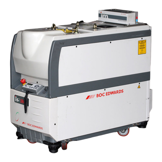
Page 14: The If System (If1800 Shown Without Panelwork)
The front panel has three pressure status LEDs (Figure 6, items 3, 5 and 6). These LEDs indicate whether the nitrogen supply pressure is too high, too low or is in the acceptable range, refer to Section 5.6. Figure 1 - The iF system (iF1800 shown without panelwork) 1. Inlet 2. -
Page 15: The Hmb Mechanical Booster Pump
The HMB pump is a positive displacement roots vacuum pump. The pump mechanism is driven by a three-phase electric motor. The HMB pump in the iF1800 system is driven through an electrical inverter, which increases the speed of the motor to 6000 r min The FDP pump backs the HMB pump: The HMB pump in an iF1800 system operates between atmospheric pressure and ultimate vacuum;... -
Page 16: Scematic Diagram Of The Fpd Pump Gas System
11. Variable restrictor (2/3-cooling purge) 24. Pressure regulator 12. Variable restrictor (inlet-purge) 25. Check-valve 13. Variable restrictor (shaft-seals purge) 26. Nitrogen supply inlet Page 6 © Edwards Limited 2009. All rights reserved. Edwards and the Edwards logo are trademarks of Edwards Limited. -
Page 17: Electrical System
HMB1800 pump in an iF1800 system. The Electrics Box has contactors for the FDP pump and the HMB pump (on an iF1800 system), pump power and current consumption sensors and short-circuit protection. The Electrics Box has a transformer and fuses for the 24 V control circuits, it also has fuses for the following supplies: iF Tool Interface Module (11) and d.c. -
Page 18: Control Module
FDP thermistor cable (19): This is used to connect the output of the thermistor in the FDP pump to the Electrics Box. HMB thermistor cable (21): On an iF1800 system, this is used to connect the output of the thermistor in the HMB pump to the Electrics Box. -
Page 19: Schematic Diagram Of The If1800 Electrical Systems
A533-23-880 Issue C Figure 3 - Schematic diagram of the iF1800 electrical systems 1. Electrics box 19. RF earth (ground) stud 37. Sensors PL2 connector 2. Gas module 20. Solenoid valve power supply * 38. Not used 3. Control module 21. -
Page 20: Controls And Indicators
Note that when you first switch-on the electrical supply, no Module will initially have control of the iF system. The Module which you want to control the iF system must take control as described above. Page 10 © Edwards Limited 2009. All rights reserved. Edwards and the Edwards logo are trademarks of Edwards Limited. -
Page 21: Services And Electrical Connections On The Rear Of The If System
B. Rear panel 19. Fuse F1 C. Detail of electric box 20. Fuse F2 D. Detail of electric box 21. Fuse F3 © Edwards Limited 2009. All rights reserved. Page 11 Edwards and the Edwards logo are trademarks of Edwards Limited. -
Page 22: Electrical Components (Shown Without Enclosures For Clarity)
20. Not used 9. Gas Module 21. HMB pump-motor thermistor cable 10. FDP pump-body temperature sensor 22. HMB inverter electrical supply cable Page 12 © Edwards Limited 2009. All rights reserved. Edwards and the Edwards logo are trademarks of Edwards Limited. -
Page 23: Setpoints, Warning And Alarm Conditions
The status LEDs (9) show the current status of the iF system and the Pump Display Terminal. © Edwards Limited 2009. All rights reserved. Page 13 Edwards and the Edwards logo are trademarks of Edwards Limited. -
Page 24: Drip Tray
The labels are placed on the iF system to: identify components; state required operating procedures; and warn of residual risks. Figures 8 and 9 show the position and text of these labels. Page 14 © Edwards Limited 2009. All rights reserved. Edwards and the Edwards logo are trademarks of Edwards Limited. -
Page 25: Exhaust Enclosure
Up/down Use these buttons to move up or down menu options or to increase or decrease a displayed parameter. © Edwards Limited 2009. All rights reserved. Page 15 Edwards and the Edwards logo are trademarks of Edwards Limited. -
Page 26: Controls And Indicatorss On The Pdt
4. CANCEL button 5. Up button 6. ENTER button 7. Menu buttons 8. Menu selected LEDs 9. Status LEDs 10. Off button Page 16 © Edwards Limited 2009. All rights reserved. Edwards and the Edwards logo are trademarks of Edwards Limited. -
Page 27: Label Fixing Positions On The Fdp And Hmb
4. Direction of Rotation Arrow 16. General warnings 5. HMB Motor Rating Information 17. Do not oil symbol 6. Warning! Risk of Electric Shock symbol © Edwards Limited 2009. All rights reserved. Page 17 Edwards and the Edwards logo are trademarks of Edwards Limited. -
Page 28: Label Positions On The If System Enclosures
16. Set voltage - Do not adjust Temperature Symbol 17. ETL listing label 8. Protective Earth symbol 9. External Protective Earth Conductor symbol Page 18 © Edwards Limited 2009. All rights reserved. Edwards and the Edwards logo are trademarks of Edwards Limited. -
Page 29: Technical Data
Maximum operating time at maximum inlet pressure Seconds (50 and 60 Hz) Inlet connection ISO160 ISO160 Outlet connection NW40 NW40 Mass Noise level <64 <69 dB(A) © Edwards Limited 2009. All rights reserved. Page 19 Edwards and the Edwards logo are trademarks of Edwards Limited. -
Page 30: If1800 Dimensions (Mm)
A. Side view B. Plan view 1. Inlet 2. Outlet (as supplied) 3. Air-extraction port 4. Lifting bolts (all 4 to be used) Page 20 © Edwards Limited 2009. All rights reserved. Edwards and the Edwards logo are trademarks of Edwards Limited. -
Page 31: Temperature Control System
20 psi (1.34 bar, 1.34 x 10 Minimum flow rate required for reliable iF system operation iF1800 6 l min © Edwards Limited 2009. All rights reserved. Page 21 Edwards and the Edwards logo are trademarks of Edwards Limited. -
Page 32: Lubrication
With cooling-water supply temperature of 20°C and a flow rate of 6 l min Lubrication Note: Edwards Material Safety Data Sheets for the oils referenced in the following sections are available on request. (Refer to Section 1.1 for contacts). 2.5.1... - Page 33 2. Levelling-foot 3. Levelling-foot 4. Levelling-foot iF1800 186.3 kg 125.8 kg 140.4 kg 132.5 kg 5. Centre of mass © Edwards Limited 2009. All rights reserved. Page 23 Edwards and the Edwards logo are trademarks of Edwards Limited.
- Page 34 A533-23-880 Issue C Figure 13 - Typical pumping speed and pump power curves for an iF1800 1. 60Hz 2. 50Hz Page 24 © Edwards Limited 2009. All rights reserved. Edwards and the Edwards logo are trademarks of Edwards Limited.
-
Page 35: Electrical Data
Motor rating (kW) Full load (A) 14.5 15.4 Motor rating (kW) Maximum input power to iF system (kW) 11.4 12.1 12.1 © Edwards Limited 2009. All rights reserved. Page 25 Edwards and the Edwards logo are trademarks of Edwards Limited. -
Page 36: Gas System
Maximum flow with inlet purge 60.5 1.02 x 10 With inlet purge off. When inlet purge is on, these flow rates will be lower Page 26 © Edwards Limited 2009. All rights reserved. Edwards and the Edwards logo are trademarks of Edwards Limited. -
Page 37: Materials In Contact With Process Gases
Table 7 - Electrics box default setpoints Parameter Unit Default setpoint values Low alarm Low warning High warning High alarm FDP power consumption HMB power consumption © Edwards Limited 2009. All rights reserved. Page 27 Edwards and the Edwards logo are trademarks of Edwards Limited. - Page 38 Only slm gas flow values are given in the table, because only slm values can be entered in the Pump Display Terminal. To convert slm values to PA ls , multiply by (1.013/60) x 10 Page 28 © Edwards Limited 2009. All rights reserved. Edwards and the Edwards logo are trademarks of Edwards Limited.
-
Page 39: Connections
Section 3.17. 2.13 Item Numbers Table 10 - Item Numbers Electrical supply iF1800 440V, 60Hz, 3-phase A533-23-974 200/208V, 50/60Hz, 3-phase A533-23-945 © Edwards Limited 2009. All rights reserved. Page 29 Edwards and the Edwards logo are trademarks of Edwards Limited. - Page 40 A533-23-880 Issue C This page has been intentionally left blank. Page 30 © Edwards Limited 2009. All rights reserved. Edwards and the Edwards logo are trademarks of Edwards Limited.
-
Page 41: Installation
The iF system is introduced for use on Load-lock chamber applications only. The pump is not configured for transfer or process use. Only Edwards engineers may install the iF pump series. Users can be trained by Edwards to conduct the tasks described in this manual, contact your local service centre or Edwards for more information. - Page 42 3.18 Adjust the interstage purge flow rates if necessary 3.19 Commission the iF system 3.20 Switch on an iF1800 system 3.20.1 Page 32 © Edwards Limited 2009. All rights reserved. Edwards and the Edwards logo are trademarks of Edwards Limited.
-
Page 43: Unpack And Inspect
Quantity Description Check( iF Dry Pumping System Pump Display Terminal Fittings Kit, comprising: Cooling-water quick-release connectors (pair) NW40 tapped ’O’ ring © Edwards Limited 2009. All rights reserved. Page 33 Edwards and the Edwards logo are trademarks of Edwards Limited. - Page 44 5. Anchor bracket (4) 2. Nut and washer 6. Cap-head screw and washer 3. Stud 7. Levelling foot 4. Block (4) 8. Pallet Page 34 © Edwards Limited 2009. All rights reserved. Edwards and the Edwards logo are trademarks of Edwards Limited.
-
Page 45: Remove The Enclosure Panels
A533-23-880 Issue C Figure 15 - Lifting bolt positions 1. Four lifting-bolts (use all four when lifting the iF1800) Remove the enclosure panels 1. Refer to Figure 16. 2. Remove the HMB left-hand side panel from the iF system: Place your hand against the top of the left-hand side panel (6) to support it and use a flat-head screwdriver ... - Page 46 7. Pins 4. Catches (on rear of item 1) 8. Screws (2 off) 5. Catches 9. Skirt cover 6. Left-hand side panel Page 36 © Edwards Limited 2009. All rights reserved. Edwards and the Edwards logo are trademarks of Edwards Limited.
-
Page 47: Locate The If System
3.6.1 iF1800 Systems The iF1800 systems are supplied with both the FDP and HMB pumps filled with oil. However, we recommend that you check the FDP and HMB oil-levels as described below. 1. Check the FDP pump oil-level. -
Page 48: Install Or Replace The Pump Display Terminal And Optional Accessories (If Necessary)
4. Place the coiled cable (7) in the recess, then place the Pump Display Terminal(8) in position in the recess (5). 3.7.2 Install optional accessories Accessories are not yet available for iF1800 rapid loadlock dry pumping systems. Please contact your nearest Edwards for more information. Connect the iF inlet to your vacuum system... -
Page 49: Connect The If Exhaust Outlet To Your Exhaust-Extraction System
Incorporate flexible pipelines in the exhaust pipeline to reduce the transmission of vibration and to prevent loading of coupling-joints. We recommend that you use Edwards braided flexible pipelines. You must be able to isolate the exhaust-outlet from the atmosphere if you have pumped or produced ... - Page 50 1. Blanking panel 7. Cable 2. Dashboard 8. Pump Display Terminal 3. Pump Display Module connector 9. Viewing angle adjuster 4. Connector Page 40 © Edwards Limited 2009. All rights reserved. Edwards and the Edwards logo are trademarks of Edwards Limited.
-
Page 51: Connect To Your Factory Extraction System (Optional)
Note: If you need further information on leak testing, contact your supplier or Edwards for advice. Leak-test the system after installation and seal any leaks found. Dangerous substances which leak from the system will be dangerous to people and there may be a danger of explosion if air leaks into the system. - Page 52 A533-23-880 Issue C Figure 18 - Leak test port positions 1. HMB pump 2. FDP pump 3. Leak-test port (blanked) 4. Support manifold Page 42 © Edwards Limited 2009. All rights reserved. Edwards and the Edwards logo are trademarks of Edwards Limited.
- Page 53 3. Pin 3 (Phase 3) 8. Connector block 4. Earth (ground) screw 9. Electrical supply connector 5. Strain releif bush 10. Electrics box © Edwards Limited 2009. All rights reserved. Page 43 Edwards and the Edwards logo are trademarks of Edwards Limited.
-
Page 54: Install Additional Safety Equipment
1. Undo screws (5) that connect the cover (4) to the Electrics box (2) and remove the cover. 2. Ensure that the common cable (6) is correctly connected to the common terminal on the terminal block (8). Page 44 © Edwards Limited 2009. All rights reserved. Edwards and the Edwards logo are trademarks of Edwards Limited. - Page 55 Isolated auxiliary contacts of the emergency stop switch on the Electrics Box. 24 V a.c. continuous output; maximum current 625 mA 0 V return © Edwards Limited 2009. All rights reserved. Page 45 Edwards and the Edwards logo are trademarks of Edwards Limited.
- Page 56 Figure 20 - Reconfigure the iF system for your electrical supply 1. iF system 2. Electrics box 3. Cover 4. Screw 5. Common cable 6. Voltage select cable 7. Terminal block Page 46 © Edwards Limited 2009. All rights reserved. Edwards and the Edwards logo are trademarks of Edwards Limited.
-
Page 57: Connect The Electrical Supply To The If System
2 metres of the iF system must be < 30 V r.m.s. If you connect the electrical supply to an iF1800 system through ELCB relays, they must be suitable for the protection of equipment with a d.c. component in the fault current, and suitable for short-duration switch-on surges, and for high leakage current (for example, type B, according to prEN50178). -
Page 58: Refit The Enclosure Panels
Phase 2 (S) Phase 3 (T) The positions of the cooling-water connectors are shown in Figure 4. Connect the cooling-water supply as follows: Page 48 © Edwards Limited 2009. All rights reserved. Edwards and the Edwards logo are trademarks of Edwards Limited. -
Page 59: Adjust The Interstage Purge Flow Rates If Necessary
6. Turn off the water supply while you complete the remainder of the installation procedures. 3.18 Adjust the interstage purge flow rates if necessary The dilution purge (3/4) flow rate can be adjusted, contact your supplier or Edwards for advice. 3.19 Commission the iF system WARNING Do not operate the iF system with the exhaust pipeline blocked. - Page 60 If you want to continue to operate the iF system, refer to Section 5. Otherwise, shut down the system,: refer to Section 5.9. Page 50 © Edwards Limited 2009. All rights reserved. Edwards and the Edwards logo are trademarks of Edwards Limited.
-
Page 61: Pump Display Terminal Menus And Display Formats
Figure 21 shows this menu control logic. © Edwards Limited 2009. All rights reserved. Page 51 Edwards and the Edwards logo are trademarks of Edwards Limited. -
Page 62: The Cancel Button
<status> This specifies the status of a sensor in the iF (a Water Flow-Switch). <Status> can be any of the following: Page 52 © Edwards Limited 2009. All rights reserved. Edwards and the Edwards logo are trademarks of Edwards Limited. -
Page 63: Wrap-Around
Here is an example of how to interpret the menu diagrams. The following procedure describes how to change the units displayed for pressures (you can select kPa or psi). © Edwards Limited 2009. All rights reserved. Page 53 Edwards and the Edwards logo are trademarks of Edwards Limited. - Page 64 Run Til Crash Units Normal display Service Serial Numbers Zero sensors Gas Valve Control Manual View Status Messages Warning and alarm messages Page 54 © Edwards Limited 2009. All rights reserved. Edwards and the Edwards logo are trademarks of Edwards Limited.
- Page 65 A533-23-880 Issue C Figure 22 - Menu logic © Edwards Limited 2009. All rights reserved. Page 55 Edwards and the Edwards logo are trademarks of Edwards Limited.
- Page 66 A533-23-880 Issue C Figure 23 - Switch on menu Page 56 © Edwards Limited 2009. All rights reserved. Edwards and the Edwards logo are trademarks of Edwards Limited.
- Page 67 A533-23-880 Issue C Figure 24 - Switch off menu © Edwards Limited 2009. All rights reserved. Page 57 Edwards and the Edwards logo are trademarks of Edwards Limited.
- Page 68 A533-23-880 Issue C Figure 25 - Normal Menu Page 58 © Edwards Limited 2009. All rights reserved. Edwards and the Edwards logo are trademarks of Edwards Limited.
- Page 69 A533-23-880 Issue C Figure 26 - status menu: sheet 1 of 2 © Edwards Limited 2009. All rights reserved. Page 59 Edwards and the Edwards logo are trademarks of Edwards Limited.
- Page 70 A533-23-880 Issue C Figure 27 - Status menu: sheet 2 of 2 Page 60 © Edwards Limited 2009. All rights reserved. Edwards and the Edwards logo are trademarks of Edwards Limited.
- Page 71 A533-23-880 Issue C Figure 28 - Control menu © Edwards Limited 2009. All rights reserved. Page 61 Edwards and the Edwards logo are trademarks of Edwards Limited.
- Page 72 A533-23-880 Issue C Figure 29 - setup menu: sheet 1 of 3 Page 62 © Edwards Limited 2009. All rights reserved. Edwards and the Edwards logo are trademarks of Edwards Limited.
- Page 73 A533-23-880 Issue C Figure 30 - setup menu: sheet 2 of 3 © Edwards Limited 2009. All rights reserved. Page 63 Edwards and the Edwards logo are trademarks of Edwards Limited.
- Page 74 A533-23-880 Issue C Figure 31 - setup menu: sheet 3 of 3 Page 64 © Edwards Limited 2009. All rights reserved. Edwards and the Edwards logo are trademarks of Edwards Limited.
- Page 75 A533-23-880 Issue C Figure 32 - Run til crash menu © Edwards Limited 2009. All rights reserved. Page 65 Edwards and the Edwards logo are trademarks of Edwards Limited.
- Page 76 A533-23-880 Issue C Figure 33 - Units menu Page 66 © Edwards Limited 2009. All rights reserved. Edwards and the Edwards logo are trademarks of Edwards Limited.
- Page 77 A533-23-880 Issue C Figure 34 - Normal display menu © Edwards Limited 2009. All rights reserved. Page 67 Edwards and the Edwards logo are trademarks of Edwards Limited.
- Page 78 A533-23-880 Issue C Figure 35 - Service menu: sheet 1 of 2 Page 68 © Edwards Limited 2009. All rights reserved. Edwards and the Edwards logo are trademarks of Edwards Limited.
- Page 79 A533-23-880 Issue C Figure 36 - Service menu: sheet 2 of 2 © Edwards Limited 2009. All rights reserved. Page 69 Edwards and the Edwards logo are trademarks of Edwards Limited.
- Page 80 A533-23-880 Issue C Figure 37 - Serial menu Page 70 © Edwards Limited 2009. All rights reserved. Edwards and the Edwards logo are trademarks of Edwards Limited.
- Page 81 A533-23-880 Issue C Figure 38 - Zero sensor menu © Edwards Limited 2009. All rights reserved. Page 71 Edwards and the Edwards logo are trademarks of Edwards Limited.
- Page 82 Figure 39 - Gas valve control menu Notes: You should only use this menu if you have been suitably trained by Edwards Service Personnel. If necessary, contact Edwards or your supplier to arrange suitable training. The actual values displayed depend on the build standard of your system (as identified by its serial number).
- Page 83 A533-23-880 Issue C Figure 40 - manual menu: sheet 1 of 3 © Edwards Limited 2009. All rights reserved. Page 73 Edwards and the Edwards logo are trademarks of Edwards Limited.
- Page 84 A533-23-880 Issue C Figure 41 - Manual menu: sheet 2 of 3 Page 74 © Edwards Limited 2009. All rights reserved. Edwards and the Edwards logo are trademarks of Edwards Limited.
- Page 85 A533-23-880 Issue C Figure 42 - Manual menu: sheet 3 of 3 © Edwards Limited 2009. All rights reserved. Page 75 Edwards and the Edwards logo are trademarks of Edwards Limited.
- Page 86 A533-23-880 Issue C Figure 43 - View status menu: sheet 1 of 2 Page 76 © Edwards Limited 2009. All rights reserved. Edwards and the Edwards logo are trademarks of Edwards Limited.
- Page 87 A533-23-880 Issue C Figure 44 - View status menu: sheet 2 of 2 © Edwards Limited 2009. All rights reserved. Page 77 Edwards and the Edwards logo are trademarks of Edwards Limited.
- Page 88 A533-23-880 Issue C Figure 45 - Message menu Page 78 © Edwards Limited 2009. All rights reserved. Edwards and the Edwards logo are trademarks of Edwards Limited.
- Page 89 A533-23-880 Issue C Figure 46 - Warning and alarm messages menu © Edwards Limited 2009. All rights reserved. Page 79 Edwards and the Edwards logo are trademarks of Edwards Limited.
- Page 90 A533-23-880 Issue C This page has been intentionally left blank. Page 80 © Edwards Limited 2009. All rights reserved. Edwards and the Edwards logo are trademarks of Edwards Limited.
-
Page 91: Operation
Configure the system (optional) The iF1800 can only be used for loadlock applications. Do not reconfigure the iF1800 for any other applications If you have a Single Pumpset Monitor connected to the iF system, the Monitor contains three configuration sets which contain preset configuration values (for example setpoints) for the iF system, for high and low nitrogen dilution levels. -
Page 92: Change The Display Format
Take control with another module and use that module to shut down the iF system. Use the emergency stop switch, as described in Section 5.11. Page 82 © Edwards Limited 2009. All rights reserved. Edwards and the Edwards logo are trademarks of Edwards Limited. -
Page 93: Check The Nitrogen Pressure And Adjust If Necessary
When you need to adjust the nitrogen pressure: Turn the pressure regulator clockwise to increase the pressure. Turn the pressure regulator anticlockwise to decrease the pressure. © Edwards Limited 2009. All rights reserved. Page 83 Edwards and the Edwards logo are trademarks of Edwards Limited. -
Page 94: Monitor The Status Of The If System
When you have read the message, press the ENTER button again; the display will then change to normal display: refer to Section 5.3. Page 84 © Edwards Limited 2009. All rights reserved. Edwards and the Edwards logo are trademarks of Edwards Limited. -
Page 95: Manual Shut-Down
15 minutes before it is shut down. When you select Auto shut-down, the following actions will occur (with a small time delay between each action): On an iF1800 system, the HMB pump is switched off. The LED on the On button on the Pump Display Terminal (Figure 7, item 1) starts to flash. - Page 96 FDP THERMISTOR HIGH (error number 512). EXHAUST PRESSURE (error number 3912). On an iF1800 system, the following alarms will cause only the HMB pump to shut down, provided 'run til crash' is not selected: HMB POWER HIGH/LOW (error numbers 810 and 812). ...
-
Page 97: Emergency Stop
Section 3.14. When emergency stop is selected: The FDP pump (and the HMB pump, on iF1800 systems) is switched off. The solenoid-valve(s) in the Gas Module close, to switch off the supply of nitrogen to the FDP pump. -
Page 98: Operation Of The If System Components
If you have connected a load-lock pump to the iF system through an Interface Module, you can use the following menus to control the operation of the load-lock pump: Switch On. Switch Off. Setup/Service/Manual/Load lock pump. Page 88 © Edwards Limited 2009. All rights reserved. Edwards and the Edwards logo are trademarks of Edwards Limited. -
Page 99: Maintenance
C. Refer to Edwards Material Safety Data Sheets for detailed information. Only Edwards engineers may maintain the iF pump series. Users can be trained by Edwards to conduct the tasks described in this manual, contact your local service centre or Edwards for more information. -
Page 100: Correct Use Of Tube Fittings
Fluorinated materials in the iF system may include oils, greases and seals. The iF system may have overheated if it was misused, if it malfunctioned or if it was in a fire. Edwards Material Safety Data Sheets for fluorinated materials used in the pump are available on request: contact your supplier or Edwards. (refer to Section 1.1 for contact numbers). -
Page 101: Maintenance Frequency
The frequency of maintenance operations depends on your process. Adjust the frequency of maintenance operations according to your experience. When you maintain the iF system, use Edwards maintenance and service kits. These contain all of the necessary seals and other components necessary to complete maintenance operations successfully. - Page 102 8. Fit a new NW40 trapped ‘O’ ring and the NW40 clamp to secure the elbow to the exhaust silencer. 9. If the check valve needs to be cleaned, refer to Section 6.6.2 Page 92 © Edwards Limited 2009. All rights reserved. Edwards and the Edwards logo are trademarks of Edwards Limited.
-
Page 103: Dismantle, Clean And Refit The Exhaust Silencer
15. Use the cap head screws and washers (retained in step 1) to secure the drip tray to the iF system. 16. Continue at step 7 of Section 6.6. © Edwards Limited 2009. All rights reserved. Page 93 Edwards and the Edwards logo are trademarks of Edwards Limited. -
Page 104: Clean The Check-Valve
5. Ensure that the fluoroelastomer ball (3) is correctly positioned in the valve body, then screw the two halves of the valve body (2, 4) together. Page 94 © Edwards Limited 2009. All rights reserved. Edwards and the Edwards logo are trademarks of Edwards Limited. -
Page 105: Check The Hmb Pump Oil-Level
Note: If there is a significant loss of oil from the pump, the shaft-seals may have failed. You cannot replace the shaft-seal. Contact your supplier or a Edwards Service Centre for advice. Use the following procedure to check the oil-level. -
Page 106: Check The Fdp Pump Oil-Level
(viewed from the front of the system). These should be used as an indication only, for an accurate oil-level assessment use the following procedure to check the oil-level. Page 96 © Edwards Limited 2009. All rights reserved. Edwards and the Edwards logo are trademarks of Edwards Limited. - Page 107 If the oil-level is below the MIN mark, fill the pump with oil until the oil-level is correct, as described in Section 6.9. 4. Refit the right-hand side enclosure panel. © Edwards Limited 2009. All rights reserved. Page 97 Edwards and the Edwards logo are trademarks of Edwards Limited.
-
Page 108: Change The Fdp Pump Oil
6. Fill the pump through the filler hole with the correct grade and quantity of oil. Allow the oil to drain into the pump, then check the oil-level on the sight-glass: refer to Section 6.7. Page 98 © Edwards Limited 2009. All rights reserved. Edwards and the Edwards logo are trademarks of Edwards Limited. -
Page 109: Relubricate The Fdp Rotor Bearings
25. Use the two M5 cap head screws removed in step 3 to refit the skirt cover to the base assembly. © Edwards Limited 2009. All rights reserved. Page 99 Edwards and the Edwards logo are trademarks of Edwards Limited. -
Page 110: Zero The Gas Module Flow Transducer
You can only change the low voltage fuses F7 to F9 for the d.c. electrical supply, the iF Interface Module and the emergency stop circuit. If any of the internal fuses F1 to F6 have failed, you must contact your supplier or Edwards for advice. -
Page 111: Replace The Pump Display Terminal
To change a fuse, refer to Figure 4 and use the following procedure. If the fuse immediately fails when you replace it, there may be an electrical fault: contact your supplier or Edwards for advice. 1. Use a flat-bladed screwdriver to undo the fuse holder (13, 14 or 15) by a 1/4 of a turn, then remove the fuse holder from the Electrics Box. -
Page 112: Fault Finding
Fault messages will be shown on the Pump Display Terminal to identify that the action you have selected cannot be carried out. The messages which can be displayed and their meanings are shown in Table 20. Page 102 © Edwards Limited 2009. All rights reserved. Edwards and the Edwards logo are trademarks of Edwards Limited. - Page 113 If the electrical connections are correct, a fuse in the Electrics Box may have failed. © Edwards Limited 2009. All rights reserved. Page 103 Edwards and the Edwards logo are trademarks of Edwards Limited.
- Page 114 The total nitrogen flow is too high. There may be a TOTAL N2 FLOW HI CHECK GAS MODULE fault in the Gas Module. Page 104 © Edwards Limited 2009. All rights reserved. Edwards and the Edwards logo are trademarks of Edwards Limited.
- Page 115 WARNING 5609 EXHAUST TEMP LOW The temperature of the exhaust is too low for the EXHAUST TEMP LOW CHECK EXHAUST process. © Edwards Limited 2009. All rights reserved. Page 105 Edwards and the Edwards logo are trademarks of Edwards Limited.
- Page 116 The gate valve connected to the iF Interface Module has failed to open. WARNING 17601 SEE MANUAL The inverter on an iF1800 system has experienced a transient power supply problem, or there is a recoverable fault. WARNING 17613 SEE MANUAL There is a fault with the RS485 data link between the inverter drive and the control module.
- Page 117 Section 3.15.2. © Edwards Limited 2009. All rights reserved. Page 107 Edwards and the Edwards logo are trademarks of Edwards Limited.
- Page 118 ALARM 17410 SEE MANUAL The inverter on an iF1800 system has been operating at less than 14 Hz for more than three minutes. There is a mechanical fault (possible a pump rotor has locked): contact your supplier or BOC Edwards for advice.
- Page 119 One or both fuses FS6 and FS8 may have tripped. Switch off the electrical supply to the iF system, then switch it on again to reset the fuse(s). © Edwards Limited 2009. All rights reserved. Page 109 Edwards and the Edwards logo are trademarks of Edwards Limited.
- Page 120 For example, the gas module flow transducer has drifted outside the valid range allowed for zeroing. ‡ For example, sensor is not fitted, or is disconnected. Page 110 © Edwards Limited 2009. All rights reserved. Edwards and the Edwards logo are trademarks of Edwards Limited.
-
Page 121: Storage And Disposal
Fluoroelastomers which may have decomposed as the result of being subjected to high temperatures Components which have been contaminated with dangerous process substances. © Edwards Limited 2009. All rights reserved. Page 111 Edwards and the Edwards logo are trademarks of Edwards Limited. - Page 122 A533-23-880 Issue C This page has been intentionally left blank. Page 112 © Edwards Limited 2009. All rights reserved. Edwards and the Edwards logo are trademarks of Edwards Limited.
-
Page 123: Service, Spares And Accessories
The majority of these centres employ Service Engineers who have undergone comprehensive Edwards training courses. Order spare parts and accessories from your nearest Edwards company or distributor. When you order, please state for each part required: Model and Item Number of your equipment ... -
Page 124: Ordering Accessories
The Active Gauge Connection Kit allows the iF system to monitor the pressure measured by an Active Gauge fitted in the inlet pipeline to the iF system. The Connection Kit is suitable for use with any of the following Edwards Active Gauges: ATC-M Active Thermocouple Gauge ... -
Page 125: If Interface Module
The iF Single Pumpset Monitor allows you to monitor pump parameters and configure the iF system. The iF Fabworks allows you to network together all of the iF systems in your installation, and to use a PC to centrally monitor the iF systems. Contact your supplier or Edwards if you want to network your iF systems. 8.5.4... -
Page 126: If Pump Display Module Extension Cables
Extension cable (display/interface), 5 m D372-72-802 Extension cable (display/interface), 10 m D372-72-803 Extension cable (display/interface), 15 m D372-72-804 Extension cable (display/interface), 25 m D372-72-805 Page 116 © Edwards Limited 2009. All rights reserved. Edwards and the Edwards logo are trademarks of Edwards Limited.
Need help?
Do you have a question about the iF1800 and is the answer not in the manual?
Questions and answers