Sign In
Upload
Download
Table of Contents
Contents
Add to my manuals
Delete from my manuals
Share
URL of this page:
HTML Link:
Bookmark this page
Add
Manual will be automatically added to "My Manuals"
Print this page
×
Bookmark added
×
Added to my manuals
Manuals
Brands
Edwards Manuals
Water Pump
iXL600
Instruction manual
Edwards iXL600 Instruction Manual
Dry pump systems
Hide thumbs
1
2
3
4
Table Of Contents
5
6
7
8
9
10
11
12
13
14
15
16
17
18
19
20
21
22
23
24
25
26
27
28
29
30
31
32
33
34
35
36
37
38
39
40
41
42
43
44
45
46
47
48
49
50
51
52
53
54
55
56
57
58
59
60
61
62
63
64
65
66
67
68
69
70
page
of
70
Go
/
70
Contents
Table of Contents
Troubleshooting
Bookmarks
Table of Contents
Table of Contents
Introduction
Scope and Definitions
Applications
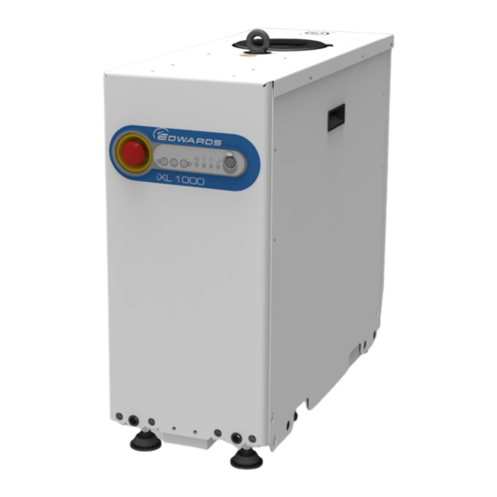
The Ixl600 and Ixl1000 Systems
The Front Panel Controls
Front View of Pumping System
The Controls/Connectors on the Rear of the Pump
Priority of Control
Green Mode
Technical Data
General Technical Data
Performance Data
Continuous Operating Zones
Loading Data
Centre of Gravity and Levelling Foot Loads
Nitrogen Purge Data
Electrical Data
Cooling Water Data
Tracer Gas Analysis
Installation
Locate the Dry Pumping System
Seismic Brackets Fitting
Seismic Bracket Front and Side Attachments with Dimensions
Lubrication
Connect the Dry Pumping System to the Vacuum/Exhaust System
Connect to the Factory Extraction System (Optional)
Connect the Nitrogen Supply
Connecting the Pump Inlet
Flammable/Pyrophoric Materials
Gas Purges
Leak Test the System
Electrical Supply
Mains Supply Cable Connection
High and Low Voltage Coding Pin Arrangement
Mains Input Supply Connector
Electrical Connector Locking Mechanism
Method for Connecting Phase Wires
Protective Earth (PE) Connection
Mains Connector on Pump Bulkhead
Connect an Additional RF Earth (Ground) (Optional)
Connect to the Emergency Stop Circuit
Semi S2 Requirements
RF Earth Connection
Connect and Set up the Cooling Water
Accessories
Commission the System
Nitrogen Flow Meter
Install Additional Safety Equipment
Operation
Start-Up
Front Panel Control Operation
PDT Operation
Microtim Operation
Status Indicators
Manual Shut-Down
Shut-Down Modes
Front Panel Control Operation
PDT Operation
Microtim Operation
Automatic Shut-Down
Unplanned Shut down and Alarms
Emergency Stop
Restart the Pump after an Emergency Stop or Automatic Shut-Down
Advanced Control and Monitoring
Maintenance
Safety and Maintenance Frequency
Relocate the System for Maintenance
Draining the Cooling Water
General Maintenance
Inspect the Connections, Pipelines, Cables and Fittings
Gas Module Configuration
Transportation, Storage and Disposal
Transportation
Storage
Disposal
Service, Spares and Accessories
Introduction
Service
Accessories
Disconnect Box
Accessory Modules
Pump Display Terminal (PDT)
PDT Holster
Pump Display Terminal
PDT Extension Cable
Water Flow Control Valve (2 Lpm) & Monitor Assembly
Earth Leakage Circuit Breaker
Seismic Restraint Brackets
Photohelic Gauge Chimney
Nitrogen Flow Switch Assembly
Interface Modules
Appendix A1 Pump Display Terminal
A1.1 Leds
A1.2 Pump Start / Stop and Control
A1.3 Warning / Alarm Display and Acknowledgement
Menus
A1.4.1 Normal Menu
Normal Menu
A1.4.2 Status Menu
A1.4.3 SETUP Menu
Status Menu
SETUP Menu
A1.4.4 COMMANDS Menu
A1.4.5 INV FAULT HIST (Display Inverter Fault History) Menu
A1.4.6 SOFTWARE VERSION Display Menu
COMMANDS Menu
INV FAULT HIST (Display Inverter Fault History) Menu
A1.4.7 FIT ACCESSORY Menu
A1.4.8 IP Configuration Menu
FIT ACCESSORY Menu
IP Configuration Menu
A1.4.9 Display Attributes Menu
Display Attributes Menu
SELECT LINE (Normal Display Selection Menu)
UNITS (Units to Display)
Appendix A2 Troubleshooting
A2.1 Warnings
A2.1.1 LED Warning Indicators
A2.1.2 PDT Warnings
A13 Warnings
A2.2 Alarms
A2.2.1 LED Alarm Indicators
A2.2.2 PDT Alarms
A14 Alarms
A2.3 Inverter Warnings and Alarms
A15 Hexadecimal to Digital Conversion
A16 Inverter Alarm Codes
A17 Inverter Warnings Codes
A2.4 Other Problems
A2.4.1 Pump Controller Communications
Advertisement
Quick Links
1
Scope and Definitions
2
The Ixl600 and Ixl1000 Systems
3
General Technical Data
4
Electrical Data
Download this manual
Instruction Manual
iXL600 and iXL1000 Dry Pump Systems
Description
iXL600 200-460 V 50/60 Hz
iXL600N 200-460 V 50/60 Hz
iXL1000 200-460 V 50/60 Hz
iXL1000N 200-460 V 50/60 Hz
Original Instructions
A540-55-880
Item Number
A541-33-010
A541-34-010
A541-53-020
A541-54-020
Issue D
Table of
Contents
Previous
Page
Next
Page
1
2
3
4
5
Advertisement
Table of Contents
Need help?
Do you have a question about the iXL600 and is the answer not in the manual?
Ask a question
Questions and answers
Related Manuals for Edwards iXL600
Water Pump Edwards iXL120N Instruction Manual
Dry pump system (60 pages)
Water Pump Edwards iXL120 Instruction Manual
Dry pump system (60 pages)
Water Pump Edwards iXH100 Instruction Manual
Dry pumping systems (88 pages)
Water Pump Edwards iXM Series Instruction Manual
Dry pump system (104 pages)
Water Pump Edwards iXM1200 Standard Instruction Manual
Dry pump system (104 pages)
Water Pump Edwards iXM1200 Customer special A Instruction Manual
Dry pump system (104 pages)
Water Pump Edwards iXM600 Standard Instruction Manual
Dry pump system (104 pages)
Water Pump Edwards iXM200 Instruction Manual
Dry pump system (104 pages)
Water Pump Edwards iXM1200 Xcede customer special A Instruction Manual
Dry pump system (104 pages)
Water Pump Edwards iXL1000 Instruction Manual
Dry pump systems (70 pages)
Water Pump Edwards iXL1000N Instruction Manual
Dry pump systems (70 pages)
Water Pump Edwards iH80 Instruction Manual
Ih series. dry pumping system (44 pages)
Water Pump Edwards iH1800 Instruction Manual
Ih series. dry pumping system (44 pages)
Water Pump Edwards iH160 Instruction Manual
Ih series. dry pumping system (44 pages)
Water Pump Edwards CDX1000 Instruction Manual
Chemical dry vacuum pumps and industrial dry vacuum pumps (82 pages)
Water Pump Edwards iF1800 Instruction Manual
Rapid loadlock dry pumping systems (126 pages)
This manual is also suitable for:
Ixl600n
Ixl1000
Ixl1000n
Table of Contents
Save PDF
Print
Rename the bookmark
Delete bookmark?
Delete from my manuals?
Login
Sign In
OR
Sign in with Facebook
Sign in with Google
Upload manual
Upload from disk
Upload from URL


Need help?
Do you have a question about the iXL600 and is the answer not in the manual?
Questions and answers