
Related Manuals for Waters ACQUITY Isocratic Solvent Manager


Summary of Contents for Waters ACQUITY Isocratic Solvent Manager
- Page 1 ACQUITY Isocratic Solvent Manager Overview and Maintenance Guide 715004208 / Revision A Copyright © Waters Corporation 2013 All rights reserved...
- Page 2 September 26, 2013, 715004208 Rev. A...
-
Page 3: General Information
Corporation assumes no responsibility for any errors that may appear in this document. This document is believed to be complete and accurate at the time of publication. In no event shall Waters Corporation be liable for incidental or consequential damages in connection with, or arising from, its use. For the most recent revision of this document, consult the Waters Web site (waters.com). -
Page 4: Contacting Waters
Contacting Waters ® Contact Waters with enhancement requests or technical questions regarding the use, transportation, removal, or disposal of any Waters product. You can reach us via the Internet, telephone, or conventional mail. Waters contact information: Contacting medium Information... -
Page 5: Considerations Specific To The Ism
Considerations specific to the ISM High voltage hazard To avoid electric shock, do not remove the device’s protective Warning: panels. The components within are not user-serviceable. FCC radiation emissions notice Changes or modifications not expressly approved by the party responsible for compliance, could void the users authority to operate the equipment. -
Page 6: Safety Advisories
For compliance with the Waste Electrical and Electronic Equipment Directive (WEEE) 2012/19/EU, contact Waters Corporation for the correct disposal and recycling instructions. September 26, 2013, 715004208 Rev. A... -
Page 7: Audience And Purpose
Audience and purpose This guide is intended for personnel who install, operate and maintain the ACQUITY isocratic solvent manager. It gives an overview of the technology and operation of the isocratic solvent manager. Intended use of the isocratic solvent manager Waters designed the isocratic solvent manager for use in liquid chromatography applications. -
Page 8: Ec Authorized Representative
EC authorized representative Waters Corporation (Micromass UK Ltd.) Floats Road Wythenshawe Manchester M23 9LZ United Kingdom Telephone: +44-161-946-2400 Fax: +44-161-946-2480 Contact: Quality manager viii September 26, 2013, 715004208 Rev. A... -
Page 9: Table Of Contents
Industrial scientific and medical classification: Industrial Scientific and Medical Group 1 Class B..............vii EC authorized representative ................ viii 1 ACQUITY Isocratic Solvent Manager ..........13 Location of the ISM in a system ..............14 Major components ..................... 15 Optional ISM kits ....................17 Flow path through the ISM with an installed Flow-splitter or Post-column Addition kit ................. - Page 10 Monitoring LEDs ....................70 Power LED ......................70 Status LED......................70 ISM control panel ....................71 3 Maintenance Procedures ..............75 Maintaining the ISM ..................76 Contacting Waters technical service..............76 Maintenance schedule ..................77 September 26, 2013, 715004208 Rev. A...
- Page 11 A Safety Advisories .................. 141 Warning symbols ....................142 Specific warnings ..................... 143 Caution advisory ....................144 Warnings that apply to all Waters instruments and devices ....145 Electrical and handling symbols ..............150 September 26, 2013, 715004208 Rev. A...
- Page 12 Electrical symbols .................... 150 Handling symbols .................... 151 B Specifications ..................153 Physical specifications ................... 153 Environmental specifications ............... 154 Electrical specifications ................. 154 Input/output specifications ................155 Performance specifications ................155 ISM ........................155 ISM flow-splitter kits..................157 Wetted materials of construction ..............158 ISM ........................
-
Page 13: Acquity Isocratic Solvent Manager
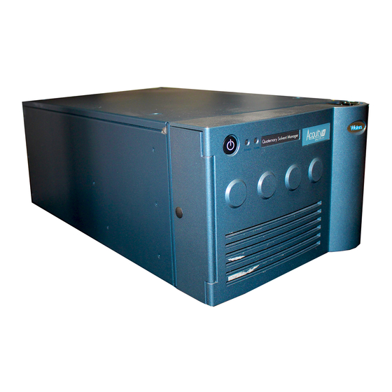
ACQUITY Isocratic Solvent Manager Waters designed the ACQUITY Isocratic Solvent Manager (ISM) to control the delivery of isocratic solvent as a make-up pump in a UPC system. The ISM, a single pump, operates at a maximum pressure of 103,421 kPa (1034 bar, 15,000 psi), and flow rates as high as 1 mL/min. -
Page 14: Location Of The Ism In A System
1 ACQUITY Isocratic Solvent Manager Location of the ISM in a system The following diagram shows the location of the ISM as a make-up pump in a typical system that includes a QDa (Quadrupole Dalton) mass detector: The ISM is typically located in the rightmost stack in a system. -
Page 15: Major Components
Major components Major components The following diagram shows the major components of the ISM: Location of pressure transducer cable connector (2) Accumulator ISM mobile phase Accumulator pump degasser chamber Power LED Run LED check valve Vent valve On/off switch Inline 22-μL filter Primary pump... - Page 16 1 ACQUITY Isocratic Solvent Manager ISM components: (Continued) Component Description Accumulator check A ball check valve that allows flow in only one valve direction. Degasser vent Vents exhaust from the degasser pump. tubing Drip tray Collects and routes fluid leaks.
-
Page 17: Optional Ism Kits
Several optional ISM kits provide for flow splitting and post-column addition. The flow-splitter kits allow you to adjust the amount of analytical flow diluted and diverted to the QDa detector. Four splitter kits are available, each specific to a Waters instrument class: ® ®... - Page 18 The Post-column Addition kit is not compatible with the UPC Note: Flow-splitter kits. Visit www.waters.com/wqp for information about optional ISM kits, including how to order them. Split ratio The split ratio depends on various factors including, but not limited to, all flow-path components downstream of the split and chromatographic conditions (flow rate and solvent composition for both LC and make-up flows).
- Page 19 Major components General guidelines When using the ACQUITY UPLC and Alliance Flow-splitter kits, observe these guidelines: • If the signal intensity in the QDa detector is low, switch to a restrictor module with a lower numeric label that allows more analytical flow to the QDa detector.
- Page 20 1 ACQUITY Isocratic Solvent Manager Restrictor module 100: Mobile phase concentration at Make-up flow QDa detector Organic Composition Minimum % Maximum % Isopropanol 10% organic 50% organic Methanol 10% organic 50% organic Acetonitrile 10% organic 50% organic Restrictor module 250:...
- Page 21 Major components Restrictor module 5: (Continued) Mobile phase concentration at Make-up flow QDa detector Organic Composition Minimum % Maximum % Methanol 10% organic 27.2 50% organic 25.1 Acetonitrile 10% organic 28.2 50% organic 29.3 Restrictor module 10: Mobile phase concentration at Make-up flow QDa detector Organic...
-
Page 22: Flow Path Through The Ism With An Installed Flow-Splitter Or Post-Column Addition Kit
1 ACQUITY Isocratic Solvent Manager Flow path through the ISM with an installed Flow-splitter or Post-column Addition kit The following diagrams show the flow path through the ISM with an installed Flow-splitter or Post-column Addition kit. Flow through the ISM with an installed ACQUITY UPLC or Alliance... - Page 23 Flow path through the ISM with an installed Flow-splitter or Post-column Addition kit The accumulator piston delivers solvent, under pressure, to the vent valve and the inline 22-µL filter. From the inline 22-µL filter, the solvent flows to the ACQUITY UPLC or Alliance flow-splitter.
- Page 24 1 ACQUITY Isocratic Solvent Manager The primary piston delivers solvent to the accumulator, the vent valve, and the inline 22-µL filter during transfer. The accumulator piston delivers solvent, under pressure, to the vent valve and the inline 22-µL filter. From the inline 22-µL filter, the solvent flows to the UPC Flow-splitter.
- Page 25 Flow path through the ISM with an installed Flow-splitter or Post-column Addition kit The primary piston delivers solvent to the accumulator, the vent valve, and the inline 22-µL filter during transfer. The accumulator piston delivers solvent, under pressure, to the vent valve and the inline 22-µL filter.
- Page 26 1 ACQUITY Isocratic Solvent Manager The filtered solvent flows through the primary check valve and into the piston chamber. The primary piston delivers solvent to the accumulator, the vent valve, and the inline 22-µL filter during transfer. The accumulator piston delivers solvent, under pressure, to the vent valve and the inline 22-µL filter.
-
Page 27: Preparing For Operation
Preparing for Operation Preparing the ISM for operation involves installing the leak sensors and flow-splitters, plumbing the waste tubing, priming the device, and monitoring system status. Contents: Topic Page Stacking system modules ..............28 Installation recommendations for fittings ........29 Installing the optional leak sensor.......... -
Page 28: Stacking System Modules
2 Preparing for Operation information and Controlling Contamination in Ultra Performance LC/MS and HPLC/MS Systems on the ACQUITY Chromatography System CD. To avoid damaging components of the ISM, do not pressurize Caution: solvent reservoirs in excess of 34.5 kPa (0.34 bar, 5 psi). To ensure the solvent manager’s optimal performance, Recommendation: elevate the solvent bottles above the pump inlet and vent properly. -
Page 29: Installation Recommendations For Fittings
Installation recommendations for fittings If the next module does not have alignment pins and slots, place it Note: atop the ISM. Lower the front of the added module so that its front alignment pin rests in the front alignment slot on the ISM. Repeat step 3 step 4... - Page 30 2 Preparing for Operation When tightening system fittings, consult the following table. Installation recommendations for ACQUITY ISM fittings: Fitting Recommended tightening Long 1/4-28 fitting with flangeless Finger-tight ferrule and stainless-steel lock ring, installed on 1/8-inch outside diameter (OD) tubing. End of lock ring with smaller inside diameter (ID) TP03377 Lock ring...
- Page 31 Installation recommendations for fittings Installation recommendations for ACQUITY ISM fittings: (Continued) Fitting Recommended tightening Short 1/4-28 fitting with flangeless Finger-tight ferrule and stainless-steel lock ring, installed on .062-inch OD tubing. End of lock ring with smaller ID TP03379 Lock ring Ferrule Stainless-steel (gold-plated) fitting with Finger-tight, plus 3/4-turn...
- Page 32 2 Preparing for Operation Installation recommendations for ACQUITY ISM fittings: (Continued) Fitting Recommended tightening Stainless-steel (gold-plated) fitting with Finger-tight, plus 3/4-turn short flats and 2-piece stainless-steel using wrench ferrule. 3/4-turn TP03375 Short flats 2-piece ferrule Stainless-steel (gold-plated) fitting with Finger-tight, plus up to short flats and 2-piece stainless-steel 1/6-turn using wrench ferrule.
-
Page 33: Installing The Optional Leak Sensor
Installing the optional leak sensor Installing the optional leak sensor The ISM can employ an optional leak sensor for detecting and collecting leakage. To prevent injury, always observe Good Laboratory Practices Warning: when you handle solvents, change tubing, or operate the ISM. Consult the Material Safety Data Sheets regarding the solvents you use. - Page 34 2 Preparing for Operation Turn the vent tubing retainer counterclockwise, and then lift the vent tubing from the drip tray by pulling upward on it and moving it to the right-hand side of the leak sensor. Vent tubing Vent tubing retainer Carefully unpack the new leak sensor.
-
Page 35: Resolving Leak Sensor Errors
Resolving leak sensor errors Plug the leak sensor connector into the receptacle on the front of the instrument. Leak sensor connector receptacle Power-on the ISM. 10. In the Instrument console, select Isocratic Solvent Manager from the system tree. 11. In the ISM information window, click Control > Reset ISM, to reset the ISM. - Page 36 2 Preparing for Operation Required materials • Cotton swabs • Gloves: clean, powder-free, chemical-resistant • Nonabrasive, lint-free wipes To resolve a leak sensor error: In the Instrument console’s Leak Sensors dialog box, confirm that the ISM’s leak sensor detected a leak. If a leak is detected, a “Leak Detected”...
- Page 37 Resolving leak sensor errors Turn the vent tubing retainer counterclockwise, and then lift the vent tubing from the drip tray by pulling upward on it and moving it to the right-hand side of the leak sensor. Vent tubing Vent tubing retainer To avoid damaging the leak sensor, do not grasp it by the Caution: ribbon cable.
- Page 38 2 Preparing for Operation Use a nonabrasive, lint-free wipe to dry the leak sensor ISM. Prism Lint-free wipe TP02891 Roll up a nonabrasive, lint-free wipe, and use it to absorb the liquid from the leak sensor reservoir and its surrounding area. Rolled up lint-free wipe Leak sensor...
- Page 39 Resolving leak sensor errors 10. Align the leak sensor’s T-bar with the slot in the side of the leak sensor reservoir, and slide the leak sensor into place. T-bar Slot in leak sensor reservoir 11. If you detached the connector from the receptacle on the front of the instrument, reattach it.
-
Page 40: Installing The Waste Tubing And Vent Tubing For The Degasser
2 Preparing for Operation Installing the waste tubing and vent tubing for the degasser To install the tubing: To prevent contamination and possible contact with Caution: solvent, wear clean, chemical-resistant, powder-free gloves when installing or removing the waste and degasser vent tubing. Wet the barbed drain fitting at the bottom of the ISM with methanol. - Page 41 Installing the waste tubing and vent tubing for the degasser To avoid releasing solvent vapors into the room, route Warning: the degasser’s vent tubing to a fume hood or other suitable exhaust system, or to a suitable waste container, ensuring the tubing's discharge end is at all times above the fluid level.
-
Page 42: Installing The Optional Acquity Uplc Or Alliance Flow-Splitter Kit
2 Preparing for Operation Representation of a suitable waste container: Waste tubing (from stack of system modules) Location of degasser vent tubing and waste tubing Waste container (from stack of system vent tubing modules) (to fume hood) Waste container TP03477 Installing the optional ACQUITY UPLC or Alliance Flow-splitter kit Install the flow-splitter kit on the ISM to dilute the eluent entering the... - Page 43 Installing the optional ACQUITY UPLC or Alliance Flow-splitter kit The ACQUITY UPLC and Alliance Flow-splitter kits are similar in Note: design, but include different restrictor modules. Required materials • Gloves: clean, powder-free, chemical-resistant • ACQUITY UPLC or Alliance Flow-splitter kit Required tool ®...
- Page 44 2 Preparing for Operation Using the T10 TORX driver, remove the five screws that secure the blank face plate to the front face of the ISM chassis. Screws securing Blank face plate blank face plate Screws securing blank face plate Disconnect the vacuum tubing that is attached to the back of the degassing chamber.
- Page 45 Installing the optional ACQUITY UPLC or Alliance Flow-splitter kit Using the T10 TORX driver, remove the screw that secures the degassing chamber and label to the front of the face plate, and then remove them from the face plate. Screw securing degasser and label to face plate Install the degasser and label on the flow-splitter face plate assembly.
- Page 46 2 Preparing for Operation Reconnect the vacuum tubing that was removed in step 3 to the back of the degassing chamber that is now attached to the flow-splitter face plate assembly. Location of vacuum tubing Install the flow-splitter face plate assembly in the front face of the ISM chassis.
- Page 47 Installing the optional ACQUITY UPLC or Alliance Flow-splitter kit Connect the tubing to one of the three restrictor modules, as shown in the following diagram. Recommendations: • Use one-piece, finger-tight, PEEK fittings for all restrictor module tubing connections. • When installing the Alliance Flow-splitter kit, use a .009-inch ID × 40.6 cm (16 inches) length of tubing to connect outlet 1 to the optical detector.
-
Page 48: Changing The Split Ratio
Degasser Degasser outlet inlet Waters recommends connecting a 1724 kPa (17 bar, Recommendation: 250 psi) backpressure regulator assembly to the outlet of the optical detector when splitting in an Alliance or ACQUITY UPLC system. For an Alliance system, the backpressure regulator is included in the Alliance splitter kit;... -
Page 49: Installing The Optional Acquity Upc Flow-Splitter Kits
Installing the optional ACQUITY UPC Flow-splitter kits To change the split ratio: Disconnect the inlet 1, outlet 1, inlet 2, and outlet 2 tubing from the restrictor module. Restrictor module (3) Outlet 1: Inlet 2: Inlet 1: Outlet 2: From ISM From To optical To QDa... - Page 50 2 Preparing for Operation Required tool T10 TORX driver (startup kit) To install the optional ACQUITY UPC Dual-Detection Flow-splitter kit: Disconnect the finger-tight fittings from the outlet and inlet of the degasser. Degasser Degasser outlet inlet Using the T10 TORX driver, remove the five screws that secure the blank face plate to the front face of the ISM chassis.
- Page 51 Installing the optional ACQUITY UPC Flow-splitter kits Disconnect the vacuum tubing that is attached to the back of the degassing chamber. Location of vacuum tubing Using the T10 TORX driver, remove the screw that secures the degassing chamber and label to the front of the face plate, and then remove them from the face plate.
- Page 52 2 Preparing for Operation Using the T10 TORX driver, tighten the captive screws on the restrictor module to the extent possible. Captive screws Install the degasser and label on the flow-splitter face plate assembly. Secure the degasser and label to the face plate assembly with the screw removed in step 4, using the T10 TORX driver to tighten the screw.
- Page 53 Installing the optional ACQUITY UPC Flow-splitter kits Reconnect the vacuum tubing that was removed in step 3 to the back of the degassing chamber that is now attached to the flow-splitter face plate assembly. Location of vacuum tubing Install the Flow-splitter assembly in the front face of the ISM chassis. Secure the face plate to the ISM with the screws removed in step using the T10 TORX driver to tighten the screws.
- Page 54 2 Preparing for Operation 10. Connect outlet 1 to inlet 3, as shown in the following diagram. Tighten the fittings 3/4 to 7/8-turn past finger-tight. Notes: • Remove the black O-rings prior to installing the tubing. The O-rings on the tubing are used to hold the fittings in place during shipping. •...
- Page 55 Installing the optional ACQUITY UPC Flow-splitter kits • The optical detector outlet tubing, ISM filter outlet tubing, and Convergence Manager tee inlet tubing are supplied in the splitter kit. Inlet 1: From optical detector Inlet 2: Outlet 2: Outlet 3: To Convergence From ISM To QDa detector...
-
Page 56: Flow-Splitter Kit
2 Preparing for Operation Installing the optional ACQUITY UPC Triple-Detection Flow-splitter kit Required materials • Gloves: clean, powder-free, chemical-resistant • ACQUITY UPC Triple-Detection Flow-splitter kit To install the optional ACQUITY UPC Triple-Detection Flow-splitter kit: Disconnect the finger-tight fittings from the outlet and inlet of the degasser. - Page 57 Installing the optional ACQUITY UPC Flow-splitter kits Disconnect the vacuum tubing that is attached to the back of the degassing chamber. Location of vacuum tubing Using the T10 TORX driver, remove the screw that secures the degassing chamber and label to the front of the face plate, and then remove them from the face plate.
- Page 58 2 Preparing for Operation Using the T10 TORX driver, tighten the captive screws on the restrictor module to the extent possible. Captive screws Install the degasser and label on the flow-splitter face plate assembly. Secure the degasser and label to the face plate assembly with the screw removed in step 4, using the T10 TORX driver to tighten the screw.
- Page 59 Installing the optional ACQUITY UPC Flow-splitter kits Reconnect the vacuum tubing that was removed in step 3 to the back of the degassing chamber that is now attached to the flow-splitter face plate assembly. Location of vacuum tubing Install the Flow-splitter assembly in the front face of the ISM chassis. Secure the face plate to the ISM with the screws removed in step using the T10 TORX driver to tighten the screws.
- Page 60 2 Preparing for Operation 10. Connect outlet 1 to inlet 3, as shown in the following diagram. Tighten the fittings 3/4 to 7/8-turn past finger-tight. Notes: • Remove the black O-rings prior to installing the tubing. The O-rings on the tubing are used to hold the fittings in place during shipping. •...
-
Page 61: Installing The Optional Post-Column Addition Kit
Installing the optional Post-column Addition kit • The optical detector outlet tubing, ISM filter outlet tubing, and Convergence Manager tee inlet tubing are supplied in the splitter kit. Inlet 1: From optical detector Inlet 2: Outlet 4: Outlet 2: Outlet 3: From ISM To third To Convergence... - Page 62 2 Preparing for Operation introduces additional solvent immediately upstream from the QDa detector. Any additional detectors upstream from the QDa detector remain unaffected by the kit's installation. Required materials • Gloves: clean, powder-free, chemical-resistant • Post-column Addition kit Required tool T10 TORX driver (startup kit) To install the optional Post-column Addition kit: Hold the post-column addition bracket securely against the blank plate...
- Page 63 Installing the optional Post-column Addition kit Secure the post-column addition bracket with the two bracket screws that are provided in the Post-Column Addition kit, and then use the T10 TORX driver to tighten them. Blank plate Bracket screw (2) Post-column Addition bracket Connect the tubing as shown in the following diagram.
-
Page 64: Connecting To The Electricity Source
2 Preparing for Operation Connecting to the electricity source Each system module requires a separate, grounded power source. The ground connection in all electrical outlets must be common and physically close to the system. To avoid electrical shock, observe these precautions: Warning: •... - Page 65 Priming the seal-wash system Caution: • To avoid damaging the solenoid valve seats and seals in the solvent path, do not use a nonvolatile buffer as the seal-wash solvent. • To avoid clogging system tubing, ensure the seal-wash solvent is 100% compatible with the mobile phase conditions.
- Page 66 2 Preparing for Operation The seal-wash routine is self-priming. Nevertheless, using a syringe to Tip: draw seal wash through the system hastens the process. To prime the seal-wash system: Remove the seal wash outlet tubing from the seal wash waste fitting (on the right-hand side of the drip tray).
-
Page 67: Priming The Ism
Priming the ISM Priming the ISM You must prime the ISM when it or the system that it is part of has never been used. You must also prime it when you restart a system, after the system has been idle for more then four hours, or when you change reservoirs or solvents. -
Page 68: Priming A Dry Ism Using A Syringe
2 Preparing for Operation In the Time box, specify the number of minutes from 0.1 through 60.0. 2.0 minutes Default: All solvent tubing must contain solvent. Prime the ISM Requirement: until a steady flow exits the vent tubing (typically requires 7 to 10 minutes). - Page 69 Priming the ISM Follow the stainless-steel solvent vent tubing from port 4 on the vent valve, and lift it from the drip tray. Vent valve Solvent vent tubing Drip tray Push the syringe plunger fully into the syringe barrel. Connect the tubing adapter to the syringe. Connect the syringe assembly to a short length of Pharmed tubing, and then connect the short length of Pharmed tubing to the solvent vent tubing you lifted from the drip tray in...
-
Page 70: Monitoring Leds
2 Preparing for Operation In the Time box, specify the number of minutes, from 0.1 through 60.0. The default setting is 2.0 minutes. Nevertheless, Recommendation: prime the isocratic solvent manager until a steady flow exits the vent tubing (typically 3 minutes). 10. -
Page 71: Ism Control Panel
Indicates a failure of the ISM that prevents its further operation. Power-off the module, and then restart it. If the LED is still steady red, contact your Waters service representative. ISM control panel The control panel of the ISM displays flow status, system pressure and total flow rate. - Page 72 2 Preparing for Operation The following table describes the items in the ISM control panel. ISM control panel items: Control panel item Description Flow LED Displays on the front panel of the solvent manager the status of the flow state, unless communications are lost.
- Page 73 ISM control panel Additional functions in the ISM control panel: (Continued) Control panel function Description Prime seal wash Starts priming the seal wash which lubricates the plungers, fills the tubing paths with solvent and flushes away solvent and or any precipitated salts that have been dragged past the plunger seals from the high-pressure side of the piston chambers.
- Page 74 2 Preparing for Operation September 26, 2013, 715004208 Rev. A...
-
Page 75: Maintenance Procedures
Maintenance Procedures Keep to a maintenance schedule, and perform maintenance as required and described in this chapter. Contents: Topic Page Maintaining the ISM ............... 76 Maintenance schedule ..............77 Spare parts ..................79 Safety and handling ................. 79 Replacing the seal wash solvent filter ..........80 Replacing the ISM solvent filter ............. -
Page 76: Maintaining The Ism
Waters Technical Service (800 252-4752). From elsewhere, phone the Waters corporate headquarters in Milford, Massachusetts (USA), or contact your local Waters subsidiary. The Waters web site includes phone numbers and e-mail addresses for Waters locations worldwide. Visit www.waters.com. -
Page 77: Maintenance Schedule
Maintenance schedule Be prepared to provide the serial numbers of the instruments or devices in your system when you contact Waters customer support. To view the information for a system module: In the Instrument console, select a module from the system tree. - Page 78 3 Maintenance Procedures Recommended routine maintenance schedule: (Continued) Maintenance Required frequency For information... procedure Replace the air filter in During scheduled page 83. the door routine maintenance or as needed Replace the optional As needed page leak sensor Replace a restrictor As needed page 87 module in the optional...
-
Page 79: Spare Parts
Spare parts Spare parts To ensure that your system operates as designed, use only Waters Quality ® Parts . Visit www.waters.com/wqp for information about Waters Quality Parts, including how to order them. Safety and handling Bear in mind the following safety considerations when performing... -
Page 80: Replacing The Seal Wash Solvent Filter
3 Maintenance Procedures Replacing the seal wash solvent filter To prevent injury, always observe Good Laboratory Practices Warning: when you handle solvents, change tubing, or operate the ISM. Consult the Material Safety Data Sheets regarding the solvents you use. Wear clean, chemical-resistant, powder-free gloves when Caution: handling the solvent filter. -
Page 81: Replacing The Ism Solvent Filter
Replacing the ISM solvent filter Replacing the ISM solvent filter To prevent injury, always observe Good Laboratory Practices Warning: when you handle solvents, change tubing, or operate the ISM. Consult the Material Safety Data Sheets regarding the solvents you use. Wear clean, chemical-resistant, powder-free gloves when Caution: handling the solvent filter. - Page 82 3 Maintenance Procedures Unscrew the finger-tight fitting and remove the old ISM solvent filter, ferrule, and fitting from the solvent tubing. Finger-tight fitting Ferrule Filter Separate the new filter assembly and place the new finger-tight fitting and ferrule onto the solvent tubing. Insert the solvent tubing into the filter, ensuring that it bottoms out in the filter.
-
Page 83: Cleaning The Air Filter In The Door
Cleaning the air filter in the door Cleaning the air filter in the door Required materials Mild detergent and water To clean the air filter: Lift the air filter, removing it from the frame. Frame Air filter Using a mild detergent and water clean the filter and then dry it. Align the cleaned air filter within the air filter frame. -
Page 84: Replacing The Optional Leak Sensor
3 Maintenance Procedures To replace the air filter: Remove the old air filter from the air filter frame, and discard it. Frame Air filter Align the new air filter within the air filter frame. Replacing the optional leak sensor To prevent injury, always observe Good Laboratory Practices Warning: when you handle solvents, change tubing, or operate the ISM. - Page 85 Replacing the optional leak sensor To replace the leak sensor: To avoid damaging electrical components or circuitry of a Caution: system module, do not disconnect an electrical assembly from the module while the module remains connected to the ac supply source. Follow this procedure to completely interrupt power to the module: Set the module’s power switch to Off.
- Page 86 3 Maintenance Procedures Remove the leak sensor from its reservoir, grasping it by its serrations, and pull upward on it. Serrations Unpack the new leak sensor. Align the leak sensor’s T-bar with the slot in the side of the leak sensor reservoir, and slide the leak sensor into place.
-
Page 87: Replacing A Restrictor Module In The Optional Acquity Uplc Or Alliance Flow-Splitter Kit
Replacing a restrictor module in the optional ACQUITY UPLC or Alliance Flow-splitter kit Replacing a restrictor module in the optional ACQUITY UPLC or Alliance Flow-splitter kit Required materials • Gloves: clean, powder-free, chemical-resistant • Restrictor module Required tool T10 TORX driver (startup kit) To replace a restrictor module: Disconnect the inlet 1, outlet 1, inlet 2, and outlet 2 tubing from the restrictor module that you are replacing. -
Page 88: Replacing The Restrictor Module In The Optional Acquity Upc Flow-Splitter Kit
3 Maintenance Procedures Using the T10 TORX driver, loosen the two captive screws on the restrictor module you are replacing, and then remove the module. Restrictor module (3) Captive screws Insert the new restrictor module into the flow-splitter assembly. Using the T10 TORX driver, tighten the captive screws on the restrictor module to the extent possible. - Page 89 Replacing the restrictor module in the optional ACQUITY UPC Flow-splitter kit If you are replacing the restrictor module in the ACQUITY UPC Note: Triple Detection Flow-splitter kit, you must also disconnect the outlet 4 tubing from the restrictor module. Inlet 3 Outlet 2: Outlet 3: To Convergence...
-
Page 90: Replacing The Inline 22-Μl Filter
3 Maintenance Procedures If you are replacing the restrictor module in the ACQUITY UPC Note: Triple Detection Flow-splitter kit, you must also connect the outlet 4 tubing to the new restrictor module. To prevent contamination, install plugs on any unused restrictor Tip: modules. - Page 91 Replacing the inline 22-µL filter The inlet side of the filter is denoted by the inscription “INLET”. Note: Inlet compression fitting Holding the 22-μL filter with the 5/8-inch, open-end wrench, disconnect the outlet compression fittings using the 1/4-inch wrench. Location of outlet compression fitting Remove the old 22-μL filter from the bracket.
-
Page 92: Replacing The Low-Pressure Filter Cartridge
3 Maintenance Procedures Replacing the low-pressure filter cartridge To avoid the harmful effects of personal contact with solvents, Warning: including inhalation, observe Good Laboratory Practice when you handle them. See the Material Safety Data Sheets for the solvents you use. Wear clean, chemical-resistant, powder-free gloves when Caution: handling the low-pressure filter cartridge. - Page 93 Replacing the low-pressure filter cartridge Unscrew the cap nut on the low-pressure inlet filter assembly. Cap nut Pull the cap nut off the tube to remove the low-pressure filter cartridge. Low-pressure filter cartridge Cap nut Tube Low-pressure filter cartridge and cap nut: Low-pressure Cap nut filter cartridge...
- Page 94 3 Maintenance Procedures Put the cap nut over the end of the tube (see the figure following step Slide the metal locking ring onto the tube, ensuring that the thicker end of the metal locking ring is facing toward the cap nut. Metal locking ring: Thinner end of Thicker end of...
- Page 95 Replacing the low-pressure filter cartridge Insert the low-pressure filter cartridge with tubing into the ferrule holder fitting. Ferrule holder fitting Low-pressure filter Cap nut 10. Screw the cap nut onto the ferrule holder fitting, ensuring that the tube is bottomed out in the in-line filter cartridge. Finger-tighten it to the extent possible.
-
Page 96: Replacing The Vent-Valve Cartridge
3 Maintenance Procedures Replacing the vent-valve cartridge To prevent injury, always observe Good Laboratory Practices Warning: when you handle solvents, change tubing, or operate the ISM. Consult the Material Safety Data Sheets regarding the solvents you use. To avoid spreading contamination, wear clean, Caution: chemical-resistant, powder-free gloves when replacing the vent-valve cartridge. - Page 97 Replacing the vent-valve cartridge Interactive display showing vent-valve setting: Filter Use the 1/4-inch wrench to remove the fittings attached to the vent-valve cartridge. Vent-valve cartridge: Hex screw in 10 o’clock position Outlet to filter Plugged From accumulator Vent to waste Use the 2-mm Allen wrench to remove the hex screw at the 10 o’clock position on the vent-valve cartridge.
- Page 98 Orient the new cartridge exactly as the old one was oriented. • The vent-valve cartridge must slide fully into the vent-valve assembly. If it does not, contact Waters Technical Service. 11. Insert the 2-mm hex screw at the 10 o’clock position on the vent-valve cartridge.
-
Page 99: Replacing The Cartridge In The Optional Solvent-Selection Valve
Replacing the cartridge in the optional solvent-selection valve Replacing the cartridge in the optional solvent-selection valve To prevent injury, always observe Good Laboratory Practice Warning: when you handle solvents, change tubing, or operate the isocratic solvent manager. Consult the Material Safety Data Sheets regarding the solvents you use. - Page 100 3 Maintenance Procedures Remove the finger-tight fittings attached to the solvent-selection valve cartridge. Solvent-selection valve cartridge: Hex screw in 10 o’clock position Outlet of valve to the low-pressure inlet filter Use the 2-mm Allen wrench to remove the hex screw at the 10 o’clock position on the cartridge.
-
Page 101: Replacing The Primary Check Valve
• The cartridge must slide fully into the solvent-selection valve assembly. If it does not, contact Waters Technical Service. 10. Insert the 2-mm hex screw at the 10 o’clock position on the cartridge, and tighten using the 2-mm Allen wrench. - Page 102 3 Maintenance Procedures Unscrew the low-pressure filter holder from the primary check valve inlet. Primary check valve inlet Low-pressure filter holder When you remove the valve assembly, ensure the PEEK Caution: washer, which is normally on the top face of the check valve, does not remain in the head (see the figure after step Use the 1/2-inch, open-end wrench to loosen the check valve, and then...
- Page 103 Replacing the primary check valve Ensure the new PEEK washer is inserted into the new check valve so that its chamfered edge faces away from the check valve. Chamfered edge PEEK washer facing away from check valve Check valve 1/2-inch Hex nut 5/16-inch, open-end wrench flat Insert the check valve assembly into the head, and use the 1/2-inch wrench to tighten the check valve nut 1/8-turn beyond finger-tight.
-
Page 104: Replacing The Accumulator Check Valve
3 Maintenance Procedures Replacing the accumulator check valve To prevent injury, always observe Good Laboratory Practices Warning: when you handle solvents, change tubing, or operate the ISM. Consult the Material Safety Data Sheets regarding the solvents you use. To prevent contamination, wear clean, chemical-resistant, Caution: powder-free gloves when replacing the check valve. - Page 105 Replacing the accumulator check valve While holding the check valve in place with the 5/16-inch, open-end wrench, use the 1/4-inch, open-end wrench to disconnect the compression fitting. Accumulator check valve Place 5/16-inch wrench here Compression fitting When you remove the valve assembly, ensure the PEEK Caution: washer, which is normally on the top face of the check valve, does not remain in the head (see the figure after...
- Page 106 3 Maintenance Procedures Make sure the new PEEK washer is inserted into the new check valve so that its chamfered edge faces away from the check valve. Chamfered edge PEEK washer facing away from check valve Check valve 1/2-inch Hex nut 5/16-inch, open-end wrench flat Insert the check valve assembly into the head, and use the 1/2-inch wrench to tighten the check valve nut 1/8-turn beyond finger-tight.
-
Page 107: Removing The Primary Head And Replacing Its Seals
Removing the primary head and replacing its seals Removing the primary head and replacing its seals See the ACQUITY online Help to help determine whether you need to replace the primary head seals. To prevent injury, always observe Good Laboratory Practices Warning: when you handle solvents, change tubing, or operate the ISM. - Page 108 3 Maintenance Procedures To remove the primary head: Flush the ISM with nonhazardous solvent. In the Instrument console, select Isocratic Solvent Manager from the system tree. In the ISM information window, click Maintain > Heads. In the Head Maintenance dialog box, select the primary head. Click Move Backward, and then wait for the plunger to stop.
- Page 109 Removing the primary head and replacing its seals Remove the seal wash tubing secured to the seal wash housing by barbed fittings, by using a tool or by pulling on the tubing as close to the pump head as possible. Seal wash Seal wash tubing...
- Page 110 3 Maintenance Procedures 11. Disconnect the pressure transducer cable from the bulkhead by squeezing on the tabs and pulling gently. Pressure transducer cable connector Tabs 12. Using the T27 TORX driver, loosen the two head bolts 1/2-turn. The bolts are accessible from the front of the pressure transducer. Head bolt (2) September 26, 2013, 715004208 Rev.
- Page 111 Removing the primary head and replacing its seals To avoid damaging the plunger, support the head from Caution: below as you remove it. 13. Using the T27 TORX driver, loosen and remove the 2 support plate bolts, and then gently pull the head and support plate off the actuator housing, making sure not to tilt the head during the extraction.
- Page 112 3 Maintenance Procedures To avoid hand lacerations, use care when removing the Warning: old plunger. Bending the plunger shaft can cause it to break. 14. Use the recessed side of the plunger removal tool to apply pressure to both sides of the release collar, and then remove the old plunger. Recessed lip of plunger removal tool TP02990...
- Page 113 Removing the primary head and replacing its seals To remove the primary plunger seals: Stand the head upright on a clean surface. Using the T27 TORX driver, completely loosen the two head bolts to release the support plate from the pump head. If you remove the transducer and head bolts, be sure to Requirement: reuse the head bolt washers when reassembling the pump head.
- Page 114 3 Maintenance Procedures Remove the old seal wash seal and discard it. Head seals: Head Fluoropolymer O-ring Seal wash housing Seal wash Plunger seal seal Plunger seal spacer Using the smooth end of the seal extraction tool, remove the plunger seal spacer from the head.
- Page 115 Removing the primary head and replacing its seals To avoid scratching any metal surfaces, use care when Caution: screwing the threaded end of the seal extraction tool into the plunger seal. Taking care not to scratch any surfaces, screw the threaded end of the seal extraction tool into the plunger seal and carefully withdraw the seal from the head.
- Page 116 3 Maintenance Procedures Inspect the pump head surface, ensuring it is free from scratches and particulates. Lubricate the new fluoropolymer O-ring with methanol, and press the O-ring into its seat with your thumbs. 10. Spray the new plunger seal with compressed air to remove any particulates.
- Page 117 Removing the primary head and replacing its seals 12. Center the new plunger seal spacer over the plunger seal so that the cross-side faces upward. Plunger seal spacer with cross-side facing up 13. Orient the seal wash housing so that the holes on its side align with the holes on the side of the head, and then guide it into place.
- Page 118 3 Maintenance Procedures 15. Install the new seal wash seal in the seal wash housing. Seal wash seal Seal wash housing 16. Place the support plate on top of the pump head, ensuring the round side of the plate is oriented toward the bottom side of the head. Round side of support plate Bottom side of...
- Page 119 Removing the primary head and replacing its seals 17. Holding the assembly together, use the T27 TORX driver, fully tighten the two head bolts until screw bottoms out then unscrew 1/4-turn. Head bolt (2) To reattach the primary head: Flip the assembly over, and then lubricate the seals with methanol. Seals Carefully insert the sapphire plunger shaft into the pump head until the plunger shaft is no longer visible, ensuring the shaft does not contact the...
- Page 120 3 Maintenance Procedures Replace the plunger whenever you replace the Recommendation: plunger seal. Plunger shaft Support plate To avoid damaging the plunger, ensure that the head Caution: assembly is not tilted relative to the actuator housing when you position it on the ISM. Carefully slide the head assembly and sapphire plunger into the actuator housing, making sure not to tilt the head.
- Page 121 Removing the primary head and replacing its seals Hold the head assembly securely against the actuator housing, and then use the T27 TORX driver to tighten the support plate bolts securely. Support plate bolt (2) Connect the pressure transducer cable to the bulkhead. Power-on the ISM.
- Page 122 3 Maintenance Procedures 14. Reattach the low-pressure filter holder to the primary check valve and finger-tighten it to the extent possible. Primary check valve inlet Low-pressure filter holder 15. Return the solvent bottles to their original location. 16. Prime the ISM (see page 67).
-
Page 123: Removing The Accumulator Head And Replacing Its Seals
Removing the accumulator head and replacing its seals Removing the accumulator head and replacing its seals See the Instrument console online Help to help determine whether you need to replace the accumulator plunger seals. To avoid the harmful effects of personal contact with solvents, Warning: including inhalation, observe Good Laboratory Practice when you handle them. - Page 124 3 Maintenance Procedures To remove the accumulator head: Flush the ISM with nonhazardous solvent. In the Instrument console, select Isocratic Solvent Manager from the system tree. In the Isocratic Solvent Manager information window, click Maintain > Heads. In the Head Maintenance dialog box, select the accumulator head. Click Move Backward, and then wait for the plunger to stop.
- Page 125 Removing the accumulator head and replacing its seals Remove the seal wash tubing secured to the seal wash housing by barbed fittings, by using a tool or by pulling on the tubing as close to the pump head as possible. Seal wash tubing Seal wash...
- Page 126 3 Maintenance Procedures 10. Using the 5/16-inch open-end wrench to hold the check-valve cartridge in place, disconnect the tubing connection from the check valve with the 1/4-inch open-end wrench. Accumulator check valve Place 5/16-inch open-end wrench here Compression fitting 11. Disconnect the pressure transducer cable from the bulkhead by squeezing on the tabs and pulling gently.
- Page 127 Removing the accumulator head and replacing its seals 12. Using the T27 TORX driver, loosen the two head bolts 1/2-turn. The bolts are accessible from the front of the pressure transducer. Tip: Head bolt (2) To avoid damaging the plunger, support the pump head Caution: from below as you remove it.
- Page 128 3 Maintenance Procedures Pulling head and support plate off actuator housing: Plunger Head and support plate September 26, 2013, 715004208 Rev. A...
- Page 129 Removing the accumulator head and replacing its seals To avoid hand lacerations, use care when removing the Warning: old plunger. Bending the plunger shaft can cause it to break. 14. Use the recessed side of the plunger removal tool to apply pressure to both sides of the release collar, and then remove the old plunger.
- Page 130 3 Maintenance Procedures To remove the accumulator head seals: Stand the head upright on a clean surface. Using the T27 TORX driver, completely loosen the two head bolts to release the support plate from the pump head. If you remove the transducer and head bolts, be sure to Requirement: reuse the head bolt washers when reassembling the pump head.
- Page 131 Removing the accumulator head and replacing its seals Remove the old seal wash seal and discard it. Head seals: Head Fluoropolymer O-ring Seal wash housing Seal wash Plunger seal seal Plunger seal spacer Using the smooth end of the seal extraction tool, remove the plunger seal spacer from the head.
- Page 132 3 Maintenance Procedures To avoid scratching any metal surfaces, use care when Caution: screwing the threaded end of the seal extraction tool into the plunger seal. Taking care not to scratch any surfaces, screw the threaded end of the seal extraction tool into the plunger seal and carefully withdraw the seal from the head.
- Page 133 Removing the accumulator head and replacing its seals Lubricate the new fluoropolymer O-ring with methanol, and press the O-ring into its seat with your thumbs. 10. Spray the new plunger seal with compressed air to remove any particulates. 11. Lubricate the new plunger seal with methanol, and use the smooth end of the seal extraction tool to place it in the head.
- Page 134 3 Maintenance Procedures 12. Center the new plunger seal spacer over the plunger seal so that the cross-side faces upward. Plunger seal spacer with cross-side facing up 13. Orient the seal wash housing so that the holes on its side align with the holes on the side of the head, and then guide it into place.
- Page 135 Removing the accumulator head and replacing its seals 14. Spray the seal wash seal with compressed air to remove any particulates. 15. Install the new seal wash seal in the seal wash housing. Seal wash seal Seal wash housing September 26, 2013, 715004208 Rev. A...
- Page 136 3 Maintenance Procedures 16. Place the support plate on top of the pump head, ensuring the round side of the plate is oriented toward the bottom side of the head. Round side of support plate Bottom side of pump head 17.
- Page 137 Removing the accumulator head and replacing its seals To reattach the accumulator head: Flip the assembly over, and then lubricate the seals with methanol. Seals Carefully insert the sapphire plunger shaft into the pump head until the plunger shaft is no longer visible, ensuring the shaft does not contact the support plate.
- Page 138 3 Maintenance Procedures Replace the plunger whenever you replace the Recommendation: plunger seal. Plunger shaft Support plate To avoid damaging the plunger, ensure that the head Caution: assembly is not tilted when you position it onto the actuator housing. Carefully slide the head assembly and sapphire plunger into the actuator housing, making sure not to tilt the head.
- Page 139 Removing the accumulator head and replacing its seals Hold the head assembly securely against the actuator housing, and then use the T27 TORX driver to tighten the support plate bolts securely. Support plate bolt (2) Connect the pressure transducer cable to the bulkhead. Power-on the ISM.
-
Page 140: Cleaning The Instrument's Exterior
3 Maintenance Procedures 15. Prime the ISM (see page 67). 16. Perform the ISM leak test (see the ACQUITY online Help). If the leak test results are not satisfactory, pressurize the head plunger seals to properly seat them. To pressurize the seals: Run the ISM at 96,527 kPa (965 bar, 14,000 psi) for a half-hour, or run the leak test until results are satisfactory. -
Page 141: A Safety Advisories
Waters offers. Contents: Topic Page Warning symbols................142 Caution advisory ................144 Warnings that apply to all Waters instruments and devices ..145 Electrical and handling symbols ............. 150 September 26, 2013, 715004208 Rev. A... -
Page 142: Warning Symbols
The following symbols warn of risks that can arise when you operate or maintain a Waters instrument or device, or a component of an instrument or device. When one of these symbols appear in a manual’s narrative sections or procedures, an accompanying statement identifies the applicable risk and explains how to avoid it. -
Page 143: Specific Warnings
Material Safety Data Sheets regarding the solvents you use. Biohazard warning The following warning applies to Waters instruments and devices that can process material containing biohazards, which are substances that contain biological agents capable of producing harmful effects in humans. -
Page 144: Caution Advisory
A Safety Advisories Biohazard and chemical hazard warning This warning applies to Waters instruments and devices that can process biohazards, corrosive materials, or toxic materials. To avoid personal contamination with biohazards, Warning: toxic materials, or corrosive materials, you must understand the hazards associated with their handling. -
Page 145: Warnings That Apply To All Waters Instruments And Devices
Warnings that apply to all Waters instruments and devices Warnings that apply to all Waters instruments and devices When operating this device, follow standard quality-control procedures and the equipment guidelines in this section. Changes or modifications to this unit not expressly approved by the Attention: party responsible for compliance could void the user’s authority to operate the... - Page 146 A Safety Advisories Use caution when working with any polymer tubing under pressure: Warning: • Always wear eye protection when near pressurized polymer tubing. • Extinguish all nearby flames. • Do not use tubing that has been severely stressed or kinked. •...
- Page 147 Warnings that apply to all Waters instruments and devices fare attenzione quando si utilizzano tubi in materiale polimerico Attenzione: sotto pressione: • Indossare sempre occhiali da lavoro protettivi nei pressi di tubi di polimero pressurizzati. • Spegnere tutte le fiamme vive nell'ambiente circostante.
- Page 148 A Safety Advisories 警告:当有压力的情况下使用管线时,小心注意以下几点: • 当接近有压力的聚合物管线时一定要戴防护眼镜。 • 熄灭附近所有的火焰。 • 不要使用已经被压瘪或严重弯曲的管线。 • 不要在非金属管线中使用四氢呋喃或浓硝酸或浓硫酸。 • 要了解使用二氯甲烷及二甲基亚枫会导致非金属管线膨胀,大大降低管线的耐压能力。 경고: 가압 폴리머 튜브로 작업할 경우에는 주의하십시오. • 가압 폴리머 튜브 근처에서는 항상 보호 안경을 착용하십시오. • 근처의 화기를 모두 끄십시오. • 심하게 변형되거나 꼬인 튜브는 사용하지 마십시오. •...
- Page 149 Warnings that apply to all Waters instruments and devices The user shall be made aware that if the equipment is used in a Warning: manner not specified by the manufacturer, the protection provided by the equipment may be impaired. L’utilisateur doit être informé que si le matériel est utilisé d’une Attention: façon non spécifiée par le fabricant, la protection assurée par le matériel risque...
-
Page 150: Electrical And Handling Symbols
A Safety Advisories Electrical and handling symbols Electrical symbols The following electrical symbols and their associated statements can appear in instrument manuals and on an instrument’s front or rear panels. Electrical power on Electrical power off Standby Direct current Alternating current Protective conductor terminal Frame, or chassis, terminal Fuse... -
Page 151: Handling Symbols
Electrical and handling symbols Handling symbols The following handling symbols and their associated statements can appear on labels affixed to the packaging in which instruments, devices, and component parts are shipped. Keep upright! Keep dry! Fragile! Use no hooks! September 26, 2013, 715004208 Rev. A... - Page 152 A Safety Advisories September 26, 2013, 715004208 Rev. A...
-
Page 153: B Specifications
Specifications The specifications presented here depend on the conditions in individual laboratories. Refer to the ACQUITY System Site Preparation Guide, or contact ® the Waters Technical Service organization for additional information about specifications. Contents: Topic Page Physical specifications ..............153 Environmental specifications ............ -
Page 154: Environmental Specifications
B Specifications Environmental specifications The following table lists the environmental specifications for the ISM. Environmental specifications: Attribute Specification Operating temperature range 4 to 40 °C Operating relative humidity range 20 to 80%, non-condensing Transportation and storage temperature -30 to 60 °C range Transportation and storage humidity 20 to 85%, non-condensing... -
Page 155: Input/Output Specifications
Input/output specifications d. Moisture Protection – Normal (IPX0) – IPX0 means that no Ingress Protection against any type of dripping or sprayed water exists. The “X” is a placeholder that identifies protection against dust, if applicable. Input/output specifications The following table lists the input and output specifications for the ISM. Input and output specifications: Attribute Specification... - Page 156 B Specifications ISM performance specifications: (Continued) Item Specification Solvent conditioning One integrated vacuum degassing channel Solvent lines Two factory installed inlet tubing assemblies for solvent and seal wash Solvent and seal wash containers Located in separate bottle tray Seal wash pump Equipped with a wash system to flush the rear of the high pressure seal and the plunger.
-
Page 157: Ism Flow-Splitter Kits
Performance specifications ISM performance specifications: (Continued) Item Specification Flow precision <0.075% RSD or <0.020 min SD, whichever is greater, based on six replicates. Test conditions: • Mobile phase: 60:40 water/methanol premix • Flow rate: 0.5 mL/min • Sample: alkylphenone mix (5.0-μL injection volume) •... -
Page 158: Wetted Materials Of Construction
B Specifications ® ® ACQUITY UPLC and Alliance Flow-splitter kit performance specifications: Item Specification Restrictor module reproducibility ± 15.0% of split ratio This specification applies to Note: replacing an individual restrictor module only. For ACQUITY UPLC and Alliance flow-splitter kits, the split ratio and Note: detector offset time are dependent on all chromatographic conditions and on the system configuration. -
Page 159: Acquity Uplc Flow-Splitter Kit
Wetted materials of construction ACQUITY UPLC Flow-splitter kit The following table lists the wetted materials of construction for the ACQUITY UPLC Flow-splitter kit. Wetted materials of construction: Description Specification Wetted materials 316 stainless-steel, fused silica Alliance Flow-splitter kit The following table lists the wetted materials of construction for the Alliance Flow-splitter kit. - Page 160 B Specifications September 26, 2013, 715004208 Rev. A...
Need help?
Do you have a question about the ACQUITY Isocratic Solvent Manager and is the answer not in the manual?
Questions and answers