
Related Manuals for Waters ACQUITY Refractive Index Detector


Summary of Contents for Waters ACQUITY Refractive Index Detector
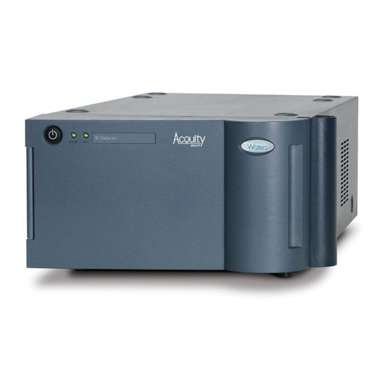
- Page 1 ACQUITY Refractive Index Detector Overview and Maintenance Guide 715003547 / Revision C Copyright © Waters Corporation 2014 All rights reserved...
- Page 2 October 13, 2014, 715003547 Rev. C...
-
Page 3: Copyright Notice
Corporation assumes no responsibility for any errors that may appear in this document. This document is believed to be complete and accurate at the time of publication. In no event shall Waters Corporation be liable for incidental or consequential damages in connection with, or arising from, its use. For the most recent revision of this document, consult the Waters Web site (waters.com). -
Page 4: Contacting Waters
Contacting Waters ® Contact Waters with enhancement requests or technical questions regarding the use, transportation, removal, or disposal of any Waters product. You can reach us via the Internet, telephone, or conventional mail. Waters contact information: Contacting medium Information Internet The Waters Web site includes contact information for Waters locations worldwide. -
Page 5: High Voltage Hazard
High voltage hazard To avoid electric shock, do not remove protective panels from Warning: ® the ACQUITY Refractive Index Detector. The components within are not user-serviceable. FCC radiation emissions notice Changes or modifications not expressly approved by the party responsible for compliance, could void the users authority to operate the equipment. -
Page 6: Safety Advisories
For compliance with the Waste Electrical and Electronic Equipment Directive (WEEE) 2012/19/EU, contact Waters Corporation for the correct disposal and recycling instructions. October 13, 2014, 715003547 Rev. C... -
Page 7: Audience And Purpose
This guide is intended for use by individuals who operate and maintain the ACQUITY refractive index detector. Intended use of the ACQUITY refractive index detector Waters designed the ACQUITY Refractive Index Detector for use in ultra-performance liquid chromatography and advanced polymer chromatography applications. It provides sensitivity, stability, and reproducibility for the analysis of components, with limited or no UV absorption. -
Page 8: Ism Classification
Class B products are suitable for use in both commercial and residential locations and can be directly connected to a low voltage, power-supply network. EC authorized representative Waters Corporation Stamford Avenue Altrincham Road Wilmslow SK9 4AX UK Telephone:... -
Page 9: Table Of Contents
Safety advisories ....................vi Operating this instrument ................. vi Applicable symbols ..................... vi Audience and purpose..................vii Intended use of the ACQUITY refractive index detector ....... vii Calibrating ......................vii Quality-control ....................vii ISM classification ....................viii ISM Classification: ISM Group 1 Class B ............viii EC authorized representative ................ - Page 10 Common refractive index detection problems ........... 23 Environmental factors ..................23 Inhomogeneities in solution ................23 Range and attenuation ..................24 Features ....................... 24 Fluid path components ..................25 Flow path......................25 Purge mode......................27 Recycle mode ...................... 29 Countercurrent heat exchanger ................ 30 Flow cell......................
- Page 11 Shutting down the detector ................66 Removing buffered mobile phase ..............67 4 Maintenance Procedures ..............69 Maintaining the detector ................. 70 Contacting Waters technical service..............70 Maintenance schedule ..................71 Configuring maintenance warnings ..............72 Spare parts ......................72 Troubleshooting with Connections INSIGHT ..........
- Page 12 Warning symbols ....................81 Task-specific hazard warnings................81 Specific warnings ....................82 Caution advisory ....................84 Warnings that apply to all Waters instruments and devices ....85 Electrical and handling symbols ..............90 Electrical symbols ....................90 Handling symbols ....................91 B Specifications ..................
-
Page 13: The Acquity Refractive Index Detector
The ACQUITY Refractive Index Detector The ACQUITY refractive index detector is designed for ultra-performance liquid chromatography and advanced polymer chromatography applications. It operates as a component of Waters ® ACQUITY systems. Refer to Appendix B, for system specifications, and to... - Page 14 1 The ACQUITY Refractive Index Detector Contents: Topic Page Location of the refractive index detector in an example system ..................15 Operating principles ................ 15 Common refractive index detection problems ........ 23 Features.................... 24 Optics ....................32 Selecting the appropriate sampling rate ........33 Filtering noise ..................
-
Page 15: Location Of The Refractive Index Detector In An Example System
Location of the refractive index detector in an example system Location of the refractive index detector in an example system The following diagram shows the location of a refractive index detector in a typical system. Bottle tray Refractive index detector TP03471 Column heater Sample manager -... - Page 16 1 The ACQUITY Refractive Index Detector The extent to which a medium refracts light is its refractive index (RI), calculated as the ratio of the velocity of light in a vacuum to the velocity of light in the medium. It is a physical property of the medium, with a dimensionless integer value represented by the letter n.
- Page 17 Operating principles over this range of compositions, but a methanol solution exhibits a nonlinear region between concentrations of 45 and 55%. Effect of density on RI: Weight percent sucrose in water Density (g/mL) Weight percent methanol in water Density (g/mL) October 13, 2014, 715003547 Rev.
- Page 18 1 The ACQUITY Refractive Index Detector Measuring refraction The extent to which a beam of light undergoes refraction when it enters a medium depends on these properties: • The angle at which the light enters a changed medium (the angle of incidence) •...
- Page 19 Operating principles The relationship between the refractive indices of the two media and the angles of incidence and refraction is described by Snell’s law: (sin θ ) = n (sin θ where = Angle of incidence θ θ = Angle of refraction = RI of medium 1 = RI of medium 2 You can use Snell’s law to calculate the RI of a sample solution from the angle...
-
Page 20: Differential Refractometry
1 The ACQUITY Refractive Index Detector Presence of sample changes the photodiode signal: Dual-element photodiode Sample in sample Collimating lens side of flow cell Sample side Reference side of flow cell of flow cell Reference side of flow cell Incident light... - Page 21 Operating principles External angle of deflection The ratio of light on the two photodiode elements, which arises from a positional change of an image cast onto the photodiode, is determined by the external angle of deflection (φ), as shown in the figure below. The external angle of deflection determines the magnitude of the shift (Δx) of a slit image cast on the photodiode by the light beam.
- Page 22 1 The ACQUITY Refractive Index Detector quartz walls of the flow cell, the solvent in the reference side of the flow cell, and the solution in the sample side of the flow cell. Of these refractive media, only the solution in the sample side of the flow cell changes over the course of a run.
-
Page 23: Common Refractive Index Detection Problems
Common refractive index detection problems By detecting how far the image shifts (Δx), the refractometer measures the difference in RI (Δn) between the solvent-sample solution and the solvent alone. The shift in the ratio of the amount of the light beam striking each element of the dual-element photodiode results in a change in the output voltage from the refractive index detector. -
Page 24: Range And Attenuation
1 The ACQUITY Refractive Index Detector Range and attenuation The total refractive index range of the detector is 1.00 to 1.75. However, for optimum performance, the usable solvent refractive index range is 1.24 to 1.60. The measurement range of the instrument is 7 × 10 to 5 ×... -
Page 25: Fluid Path Components
Detector features: (Continued) Feature Description Relief valve Prevents overpressuring the flow cell and, consequently, possible flow cell damage. Fluid path components The fluid path of the ACQUITY refractive index detector includes these components: • Countercurrent heat exchanger • End-cap heat exchanger •... - Page 26 1 The ACQUITY Refractive Index Detector Flow path during analysis: End cap heat Flow cell exchanger Fluid path for normal mode Counter current heat exchanger Relief valve Purge valve (closed) (open) Sample in Purge out Waste out October 13, 2014, 715003547 Rev. C...
-
Page 27: Purge Mode
Features Purge mode When you purge the detector, solvent flows as indicated in the following sequence: Enters through inlet tubing port. Passes through the inlet tube of the countercurrent heat exchanger. Flows through the end-cap heat exchanger. Flows through the sample side of the flow cell. Flows out to the cross fitting, bypassing the countercurrent heat exchanger. - Page 28 1 The ACQUITY Refractive Index Detector Flow path during purge: End cap heat Flow cell exchanger Cross connection Fluid path for purge mode Counter current heat exchanger Tee connection Relief valve Purge valve (open) (closed) Sample in Purge out Waste out It is best to purge the flow cell before an analysis.
-
Page 29: Recycle Mode
The recycle valve’s ports and their corresponding outlet lines are labelled accordingly. For additional information about recycling solvent, consult the See also: ACQUITY Console online Help. ACQUITY refractive index detector external plumbing and valves: Purge Pressure valve relief valve Recycle valve October 13, 2014, 715003547 Rev. -
Page 30: Countercurrent Heat Exchanger
1 The ACQUITY Refractive Index Detector Countercurrent heat exchanger Achieving a stable baseline requires precise control of the temperature of the flow cell and the fluid entering it. The low-dispersion, countercurrent heat exchanger minimizes temperature fluctuations in the sample side of the flow cell. -
Page 31: Recycle Valve
Features withstand, thus protecting the flow cell from exceeding the maximum pressure rating. The pressure rating of the relief valve is 206.8 kPa (2 bar, 30 psi). During purging, fluid moving through the sample and reference sides of the flow cell exits through the pressure relief valve and then to the waste reservoir. -
Page 32: Optics
1 The ACQUITY Refractive Index Detector Optics The detector’s optics bench assembly consists of these components: • Source lamp • Lamp lens mask • Lamp lens • Flow cell, with sample and reference sides • Mirror • Mirror mask •... -
Page 33: Selecting The Appropriate Sampling Rate
Selecting the appropriate sampling rate The detector’s optics bench directs light as follows: • Light from the source lamp is focused by the focusing lens through the aperture and collimating lens, forming a beam. • The light beam passes through the sample and reference sides of the flow cell to the mirror. -
Page 34: Filtering Noise
1 The ACQUITY Refractive Index Detector Filtering noise The detector's digital, finite-impulse-response Hamming filter minimizes noise by degrading peak height and enhancing the filtering of high frequency noise. The filter’s performance depends on the filter time-constant you select. You can program a filter time to be fast, slow, normal, or other. If you select Fast, Slow, or Normal, you need not enter a value;... -
Page 35: Polarity
Polarity The following figure shows the relationship between increased filter time-constant and absorbance. Filter time-constant comparison 0 sec 1 sec 2 sec Time (minutes) Although the peak shape shows some distortion and the signal output is Tip: delayed with different time-constants, the peak area remains the same. Polarity Detected peaks can be positive or negative. -
Page 36: Temperature Control
1 The ACQUITY Refractive Index Detector Temperature control The detector oven, which controls the temperature of the flow cell, has a temperature-setting range of 30 to 55 °C, settable to ±0.1 °C. The detector flow cell temperature reading is accessible via the console or control panel. -
Page 37: Preparing The Detector
Preparing the detector Proper solvent selection and preparation are critical in differential refractometry to prevent baseline changes such as drift, noise, or an erratic baseline. To avoid back injuries, do not attempt to lift the detector Warning: without assistance. Contents: Topic Page Stacking the modules............... -
Page 38: Stacking The Modules
2 Preparing the detector Stacking the modules To avoid back injuries, do not attempt to lift the detector Warning: without assistance. To stack the modules: Place the rear feet of the detector atop the previously added module in the system stack, and slide it backward until its rear alignment pin rests in the rear alignment slot on the module. -
Page 39: Installing The Leak Sensor
Installing the leak sensor Installing the leak sensor To avoid the harmful effects of personal contact with solvents, Warning: including inhalation, always wear chemical-resistant, powder-free gloves and observe Good Laboratory Practice when you handle them. See the Material Safety Data Sheets for the solvents you use. To avoid the harmful effects of personal contact with leaking Warning: solvents, flush the detector with an appropriate miscible solvent prior to... - Page 40 2 Preparing the detector Align the leak sensor’s T-bar with the slot in the side of the leak sensor reservoir, and slide the leak sensor into place. TP03559 T-bar Slot in leak sensor reservoir Plug the leak sensor connector into the port on the front of the detector. Leak sensor connector port on front of detector: Power-on the detector.
-
Page 41: Installation Recommendations For Fittings
Installation recommendations for fittings Installation recommendations for fittings To avoid the harmful effects of personal contact with solvents, Warning: including inhalation, always wear chemical-resistant, powder-free gloves and observe Good Laboratory Practice when you handle them. See the Material Safety Data Sheets for the solvents you use. To avoid the harmful effects of personal contact with leaking Warning: solvents, flush the detector with an appropriate miscible solvent prior to... -
Page 42: Connecting A Column Or Second Detector
2 Preparing the detector When tightening system fittings, consult the following table. Installation recommendations for detector fittings: Fitting Recommended tightening Standard 1/16-inch fitting Finger-tight, plus as much Gold-plated Ferrule as an additional 1/4-turn compression screw 1/4-turn Connecting a column or second detector Use only the insulating sample inlet tubing assembly supplied in the startup kit when connecting a column or second detector. -
Page 43: Connecting To Waste
Connecting to waste To connect a column or other detector to the refractive index detector: Insert one end of the inlet tubing assembly into the inlet port of the refractive index detector. Ensure the inlet tubing bottoms in the inlet port before Important: tightening the gold-plated compression screw. -
Page 44: Making The Recycle Connection
2 Preparing the detector Location of waste tubing on recycle valve: Location of waste tubing Making the recycle connection To make the recycle connection: Place the free end of the recycle tubing in the solvent container. If the recycle tubing was previously placed in the waste container, Note: remove it from the waste container, and then place it in the solvent container. -
Page 45: Installing The Multi-Detector Drip Tray
Installing the multi-detector drip tray Location of recycle tubing on recycle valve: Location of recycle tubing Installing the multi-detector drip tray If your system has more than one detector, you must install the multi-detector drip tray. For information on how to install the multi-detector drip tray, refer to the instructions included in the multi-detector drip tray kit. - Page 46 2 Preparing the detector I/O signal connectors: 1 2 3 4 5 6 For electrical specifications, see Appendix Refractive index detector analog-out/event-in/event-out connections: Signal connection Description Inject Start Indicates (with a contact closure output) that an injection has started. Switch Output switch to trigger external devices.
- Page 47 Making signal connections To make signal connections: Insert the connector into the connector port on the back of the detector. Connector port Connector Using the flat-blade screwdriver, attach the positive and negative leads of the signal cable to the connector. Screw Connector Signal cable...
-
Page 48: Connecting To The Electricity Source
2 Preparing the detector Use the 9/32-inch nut driver to tighten the locking nut until the fork Tip: terminal does not move. Fork terminal Locking nut Grounding stud Connecting to the electricity source Each system module requires a separate, grounded power source. The ground connection in all power outlets must be common and physically close to the system. -
Page 49: Typical Solvent Problems
Typical solvent problems Connect the male end of the power cord to a suitable wall outlet. If the system includes the optional FlexCart, ensure the Alternative: detector is powered off. Connect the female end of the cart's power supply cable (included in the startup kit) to the receptacle on the rear panel of the detector. -
Page 50: Preparation Checklist
2 Preparing the detector A dirty or impure solvent can cause these problems: • Baseline noise and drift • Plugged columns • Blockages in the fluid path Preparation checklist The following solvent preparation guidelines help to ensure stable baselines and good resolution: •... -
Page 51: Tetrahydrofuran (Thf)
Selecting a solvent Tetrahydrofuran (THF) When you use unstabilized THF, ensure that it is fresh. Previously opened containers of THF contain peroxide contaminants, which cause baseline drift. To avoid an explosion caused by unstable contaminants Warning: (peroxides) in THF, do not evaporate or otherwise concentrate THF to a state approaching dessication. -
Page 52: Solvent Degassing
2 Preparing the detector Refractive indices of common solvents: (Continued) Solvent Solvent Isopropyl chloride 1.378 Ethylene dichloride 1.445 Isopropanol 1.38 Carbon tetrachloride 1.466 n-Propanol 1.38 Dimethyl sulfoxide 1.477 (DMSO) Methylethylketone 1.381 Toluene 1.496 Diethyl amine 1.387 Xylene ~1.50 n-Propyl chloride 1.389 Benzene 1.501... -
Page 53: Solvent Degassing Methods
Solvent degassing Effects of intermolecular forces Nonpolar gases (N , CO , He) are more soluble in nonpolar solvents than in polar solvents. Generally, a gas is most soluble in a solvent with intermolecular attractive forces similar to those in the gas (“like dissolves like”). -
Page 54: Solvent Degassing Considerations
2 Preparing the detector Vacuum degassing can possibly change the composition of mixed Note: solvents. Sonication Sonication with high-energy sound waves drives energy into the solvent and causes the submicron-sized “bubbles” of gas to aggregate. As the gas bubbles aggregate, they become large enough to float out of the solvent and dissipate. Sonication alone degasses 4 liters of solvent in approximately 20 minutes. - Page 55 Solvent degassing To avoid injury from flying glass fragments, do not apply Warning: vacuum to the brown glass bottles in which solvent is shipped. Doing so creates a high risk of implosion. Use a thick-walled container designed for vacuum applications. October 13, 2014, 715003547 Rev.
- Page 56 2 Preparing the detector October 13, 2014, 715003547 Rev. C...
-
Page 57: Using The Detector
Using the detector Contents: Topic Page Starting the detector................ 58 Resolving leak sensor errors............63 Shutting down the detector ............. 66 October 13, 2014, 715003547 Rev. C... -
Page 58: Starting The Detector
3 Using the detector Starting the detector Starting the ACQUITY refractive index detector entails powering-on the detector and each system module individually, as well as the ACQUITY workstation. It also entails starting the operating software (Empower). To start the detector: Power-on the workstation. -
Page 59: Monitoring Detector Leds
Starting the detector To avoid wasting solvent when equilibrating the detector, Recommendation: set the recycle valve to the recycle position. Monitoring detector LEDs Light emitting diodes on the detector indicate its state of functioning. Power LED The power LED, to the left-hand side of the detector’s front panel, indicates when the detector is powered-on or powered-off. -
Page 60: About The Detector Control Panel
3 Using the detector About the detector control panel The detector’s control panel appears at the bottom of the Sample Set Editor page. Detector control panel: Run LED Status Recycle indicator Current flow cell Detector signal temperature Set flow cell temperature The detector control panel displays the detector status, set and current flow cell temperatures, detector signal, polarity, and recycle status. - Page 61 Starting the detector Non-modifiable detector control panel items: Control panel item Description Status Displays the status of the current operation. (Appears only if the detector is running.) Status can be: • Initializing • Getting Ready • Ready • Running • Purging •...
- Page 62 3 Using the detector You can access additional functions by right-clicking anywhere in the detector control panel. Additional functions in the detector control panel: Control panel function Description Auto zero Sets the signal output to zero immediately. Purge Starts or ends the reference flow cell purging function.
-
Page 63: Resolving Leak Sensor Errors
Resolving leak sensor errors Resolving leak sensor errors After approximately 1.5 mL of liquid accumulates in the leak sensor reservoir, an alarm sounds indicating that the leak sensor detected a leak. To avoid the harmful effects of personal contact with solvents, Warning: including inhalation, always wear chemical-resistant, powder-free gloves and observe Good Laboratory Practice when you handle them. - Page 64 3 Using the detector To avoid damaging the electronic components or circuitry Caution: of a system module, do not disconnect an electrical assembly from the module while the module remains connected to the ac supply source. Follow this procedure to completely interrupt power to the module: Set the module’s power switch to Off.
- Page 65 Resolving leak sensor errors Use a nonabrasive, lint-free wipe to dry the leak sensor prism. Prism Lint-free wipe TP03562 Roll up a nonabrasive, lint-free wipe, and use it to absorb the liquid from the leak sensor reservoir and its surrounding area. Rolled up lint-free wipe Leak sensor...
-
Page 66: Shutting Down The Detector
3 Using the detector Align the leak sensor’s T-bar with the slot in the side of the leak sensor reservoir, and slide the leak sensor into place. TP03559 T-bar Slot in leak sensor reservoir 10. Plug the leak sensor connector into the port on the front of the detector. 11. -
Page 67: Removing Buffered Mobile Phase
Shutting down the detector If you are not running the detector for less than 24 hours, set the flow rate to 0.1 mL/min, and keep the solvent manager operating to minimize the amount of time the detector needs for reequilibration when you use it again. To shut down the detector for more than 24 hours: Flush all flow paths with 100% organic solution. - Page 68 3 Using the detector October 13, 2014, 715003547 Rev. C...
-
Page 69: Maintenance Procedures
Maintenance Procedures Keep to a maintenance schedule, and perform maintenance procedures as required and described in this chapter. Contents: Topic Page Maintaining the detector ..............70 Spare parts ..................72 Troubleshooting with Connections INSIGHT ........ 72 Safety and handling ................. 74 Replacing the leak sensor .............. -
Page 70: Maintaining The Detector
Waters Technical Service (800 252-4752). From elsewhere, phone the Waters corporate headquarters in Milford, Massachusetts (USA), or contact the local Waters subsidiary. The Waters web site includes phone numbers and e-mail addresses for Waters locations worldwide. Visit www.waters.com. -
Page 71: Maintenance Schedule
Be prepared to provide the serial numbers of the instruments or devices in the system when you contact Waters customer support. To view the information for a system module: In the ACQUITY Console, select a module from the system tree. -
Page 72: Configuring Maintenance Warnings
For information on setting maintenance warnings, consult the ACQUITY Console online Help. Spare parts ® To ensure that a system operates as designed, use only Waters Quality Parts Visit www.waters.com/wqp for information about Waters Quality Parts, including how to order them. Troubleshooting with Connections INSIGHT ®... - Page 73 A .zip file containing your Connections INSIGHT profile is Result: forwarded to Waters customer support for review. Saving a service profile or plot file from the Instrument Console can Tip: require as much as 150 MB of file space.
-
Page 74: Safety And Handling
To avoid electric shock, do not remove protective panels from Warning: the refractive index detector. The panels cover components that are serviceable only by Waters technicians. To avoid damaging the electronic components or circuitry of a Caution: system module, do not disconnect an electrical assembly from the module while the module remains connected to the ac supply source. -
Page 75: Replacing The Leak Sensor
Replacing the leak sensor Replacing the leak sensor To avoid the harmful effects of personal contact with solvents, Warning: including inhalation, always wear chemical-resistant, powder-free gloves and observe Good Laboratory Practice when you handle them. See the Material Safety Data Sheets for the solvents you use. To avoid the harmful effects of personal contact with leaking Warning: solvents, flush the detector with an appropriate miscible solvent prior to... - Page 76 4 Maintenance Procedures To avoid damaging the electronic components or circuitry Caution: of a system module, do not disconnect an electrical assembly from the module while the module remains connected to the ac supply source. Follow this procedure to completely interrupt power to the module: Set the module’s power switch to Off.
-
Page 77: Decontaminating The Fluid Path
Decontaminating the fluid path Align the leak sensor’s T-bar with the slot in the side of the leak sensor reservoir, and slide the leak sensor into place. TP03559 T-bar Slot in leak sensor reservoir Plug the leak sensor connector into the port on the front of the detector. Leak sensor connector port on front of detector: Power-on the refractive index detector. - Page 78 4 Maintenance Procedures • HPLC-grade water • A strong cleaning solvent suitable for the system and application (6N nitric acid is used frequently) • A separate waste container for acid waste • If you use an acid as a cleaning solvent, a means of measuring the pH of the acid effluent If you use 6N nitric acid and operate the detector at high Caution:...
-
Page 79: Cleaning The Refractive Index Detector's Exterior
Cleaning the refractive index detector’s exterior Switch the solvent manager back to the mobile phase, and flush for 5 minutes. 10. Take the detector out of purge mode and stop the pump or solvent delivery system. 11. Reattach the column and reequilibrate the detector. Cleaning the refractive index detector’s exterior Clean surfaces of the detector using only a clean, soft, lint-free paper or clean cloth dampened with water. - Page 80 4 Maintenance Procedures October 13, 2014, 715003547 Rev. C...
-
Page 81: A Safety Advisories
Heed all warnings when you install, repair, and operate Waters instruments. Waters assumes no liability for the failure of those who install, repair, or operate its instruments to comply with any safety precaution. -
Page 82: Specific Warnings
A Safety Advisories (General risk of danger. When this symbol appears on an Warning: instrument, consult the instrument’s user documentation for important safety-related information before you use the instrument.) (Risk of burn injury from contacting hot surfaces.) Warning: (Risk of electric shock.) Warning: (Risk of fire.) Warning:... - Page 83 Biohazard warning This warning applies to Waters instruments that can be used to process material that can contain biohazards: substances that contain biological agents capable of producing harmful effects in humans.
-
Page 84: Caution Advisory
A Safety Advisories Chemical hazard warning This warning applies to Waters instruments that can process corrosive, toxic, flammable, or other types of hazardous material. Waters instruments can be used to analyze or Warning: process potentially hazardous substances. To avoid injury... -
Page 85: Warnings That Apply To All Waters Instruments And Devices
Warnings that apply to all Waters instruments and devices Warnings that apply to all Waters instruments and devices When operating this device, follow standard quality-control procedures and the equipment guidelines in this section. Changes or modifications to this unit not expressly approved by the Attention: party responsible for compliance could void the user’s authority to operate the... - Page 86 A Safety Advisories Use caution when working with any polymer tubing under pressure: Warning: • Always wear eye protection when near pressurized polymer tubing. • Extinguish all nearby flames. • Do not use tubing that has been severely stressed or kinked. •...
- Page 87 Warnings that apply to all Waters instruments and devices fare attenzione quando si utilizzano tubi in materiale polimerico Attenzione: sotto pressione: • Indossare sempre occhiali da lavoro protettivi nei pressi di tubi di polimero pressurizzati. • Spegnere tutte le fiamme vive nell'ambiente circostante.
- Page 88 A Safety Advisories 警告:当有压力的情况下使用管线时,小心注意以下几点: • 当接近有压力的聚合物管线时一定要戴防护眼镜。 • 熄灭附近所有的火焰。 • 不要使用已经被压瘪或严重弯曲的管线。 • 不要在非金属管线中使用四氢呋喃或浓硝酸或浓硫酸。 • 要了解使用二氯甲烷及二甲基亚枫会导致非金属管线膨胀,大大降低管线的耐压能力。 경고: 가압 폴리머 튜브로 작업할 경우에는 주의하십시오. • 가압 폴리머 튜브 근처에서는 항상 보호 안경을 착용하십시오. • 근처의 화기를 모두 끄십시오. • 심하게 변형되거나 꼬인 튜브는 사용하지 마십시오. •...
- Page 89 Warnings that apply to all Waters instruments and devices The user shall be made aware that if the equipment is used in a Warning: manner not specified by the manufacturer, the protection provided by the equipment may be impaired. L’utilisateur doit être informé que si le matériel est utilisé d’une Attention: façon non spécifiée par le fabricant, la protection assurée par le matériel risque...
-
Page 90: Electrical And Handling Symbols
A Safety Advisories Electrical and handling symbols Electrical symbols These can appear in instrument user manuals and on the instrument’s front or rear panels. Electrical power on Electrical power off Standby Direct current Alternating current Protective conductor terminal Frame, or chassis, terminal Fuse October 13, 2014, 715003547 Rev. -
Page 91: Handling Symbols
Electrical and handling symbols Handling symbols These handling symbols and their associated text can appear on labels affixed to the outer packaging of Waters instrument and component shipments. Keep upright! Keep dry! Fragile! Use no hooks! October 13, 2014, 715003547 Rev. C... - Page 92 A Safety Advisories October 13, 2014, 715003547 Rev. C...
-
Page 93: Physical Specifications
Physical specifications Specifications The specifications presented in this document depend on the conditions in individual laboratories. Refer to the site preparation guide or contact ® Waters Technical Service for more information on specifications. Contents: Topic Page Physical specifications ..............93 Environmental specifications ............ -
Page 94: B Specifications
B Specifications Environmental specifications The following table lists the environmental specifications for the ACQUITY refractive index detector. Environmental specifications: Attribute Specification Operating temperature 15 to 40 °C (59 to 104 °F) Operating humidity 20 to 80%, noncondensing Shipping and storage temperature −30 to 60 °C (−40 to 140 °F) Shipping and storage humidity 10 to 85%, noncondensing... -
Page 95: Input/Output Specifications
Input/output specifications – b. Overvoltage Category II Pertains to instruments that receive their electrical power from a local level such as an electrical wall outlet. – c. Pollution Degree 2 A measure of pollution on electrical circuits that can produce a reduction of dielectric strength or surface resistivity. - Page 96 B Specifications Performance specifications: (Continued) Item Specification Compatible flow rate range 0.05 to 2.0 mL/min Light source 870 nm infrared LED lamp Refractive index range 1.00 to 1.75 Usable solvent refractive index 1.24 to 1.60 range Measurement range 7.0 × 10 RIU to 5.0 ×...
-
Page 97: Wetted Materials Of Construction
<50 dB(A) above a reference sound pressure of 20 μPA in front of unit in operator position. Wetted materials of construction The following table lists the wetted materials of construction for the ACQUITY refractive index detector. Wetted materials of construction: Description Specification Wetted materials... - Page 98 B Specifications October 13, 2014, 715003547 Rev. C...
Need help?
Do you have a question about the ACQUITY Refractive Index Detector and is the answer not in the manual?
Questions and answers