Table of Contents
Advertisement
Quick Links
Advertisement
Table of Contents

Related Manuals for SATO FX3-LX


Summary of Contents for SATO FX3-LX
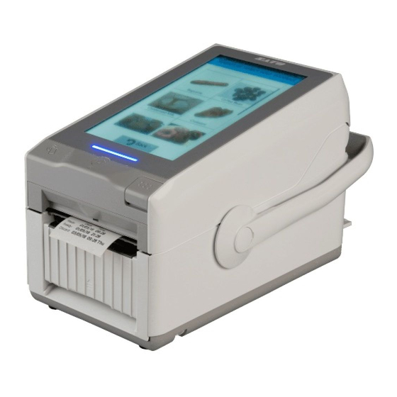
- Page 1 FX3-LX...
-
Page 2: Table Of Contents
Table of Contents Before You Start......................8 About This Manual..........................8 Features of the Product........................9 Safety Precautions........................... 10 Safety Precautions for the Battery Pack..................17 Precautions for Installation and Handling..................21 Select a Safe Location........................21 Power Supply..........................22 Printing............................23 Regulatory Approval......................... 24 Environmentally Hazardous Materials....................27 Copyrights/Limitation of Liability/Trademarks...................28 Copyrights............................28... - Page 3 Side View..........................80 Bottom View........................... 82 Installing the Options........................84 Installing the Optional Cutter Kit/Partial Cutter Kit..............84 Installing the Optional Linerless Kit..................86 Installing the Optional Wireless LAN/Bluetooth Kit..............89 Installing the Optional Wall Mount Kit..................92 Powering On/Off the Printer......................98 Connecting to Power........................98 Connecting the AC Adapter and the Power Cord..............
- Page 4 Loading the Media Roll (Printing in Cutter Mode/Partial Cutter Mode)........200 Loading the Media Roll (Printing in Linerless Tearoff Mode)..........204 Loading the Media Roll (Printing in Linerless Cutter Mode)..........208 Loading the Fan-fold Media...................... 212 When to Replace Media.........................215 Printer Settings.......................218 The [Settings] Menu........................
- Page 5 [Test Print]..........................292 [HEX-Dump]..........................297 [Profiles]..........................302 [Service]..........................303 [Factory]..........................304 [Wi-Fi Site Survey]....................... 304 [Install Certificates]....................... 304 [Delete Certificates]......................305 [Clone]..........................305 [Startup Guide]........................306 [Information] Menu........................307 [Help]............................ 307 [Build Version]........................309 [Applications]........................309 [Print Module]........................309 [Sensor Module]........................309 [Counters]..........................310 [LAN] (USB+LAN Model Only).....................310 [Wi-Fi]...........................
- Page 6 Operating the Notification Screen of the SOS (SATO Online Services) On-Demand Mode (SOS users only)..........................436 Operating the Date and Time Settings Notification Screen of SOS (SATO Online Services) (SOS users only)..........................438 SOS (SATO Online Services) Application (SOS users only)............442...
- Page 7 When an Error Message Appears....................443 Error Message Indication and Operating Procedure When the SOS (SATO Online Services) Is Enabled (SOS users only)......................483 Contact Information for When You Are in Trouble.................484 Product Specifications...................485 Printer Specifications........................485 Hardware........................... 485 Interface............................. 489 Supported Interfaces......................
-
Page 8: Before You Start
About This Manual Thank you for purchasing this SATO FX3-LX printer (hereafter referred to as "the printer"). This manual supplies basic information on how to operate the FX3-LX. Read the manual carefully to understand each function of FX3-LX before operation. -
Page 9: Features Of The Product
Features of the Product FX3-LX is an All-in-One printing solution which offers intuitive printing applications and can be customized to meet the customer's requirements. This printer optimizes business processes in a wide range of markets like food, retail, healthcare, event ticketing and manufacturing. The main features are as follows: •... -
Page 10: Safety Precautions
Safety Precautions Safety Precautions This topic describes how to use the product safely. Be sure to read the following information carefully before using the product. Pictographic Symbols This operator manual and the product labels use a variety of pictographic symbols. These symbols emphasize the safe and correct use of the product and to prevent injury to others and property damage. - Page 11 If they are spilled and get inside the product, immediately turn off the power switch, unplug the power cord from the outlet, and contact your SATO reseller or technical support center. Using the product in this condition could cause a fire or electric shock.
- Page 12 If the product is dropped or broken, immediately turn off the power switch, unplug the power cord from the outlet, and contact your SATO reseller or technical support center. Using the product in this condition could cause a fire or electric shock.
- Page 13 • If the AC adapter is damaged (the wires exposed or broken), contact your SATO reseller or technical support center. If you operate the product in this condition, it may cause fire or electric shock. Handling the AC Adapter •...
- Page 14 Safety Precautions • If you notice any unusual odor, deformation, fluid leakage or other unusual conditions during use, charging or storage, stop using the battery to avoid risk of fire, personal injury and electric shock. • If you notice any leakage or unusual odor, keep the battery away from fire immediately.
- Page 15 It may cause skin rashes. • If you notice any rust, unusual odor, overheating, or other unusual Battery pack conditions during your first use after purchase, stop using the battery pack and contact your SATO reseller or technical support center.
- Page 16 Safety Precautions • Be sure to charge the battery pack before its first use or when it has not been used for a long time. • When not using the battery pack, store it in a location with low humidity to avoid the battery from leaking or rusting. •...
-
Page 17: Safety Precautions For The Battery Pack
Safety Precautions for the Battery Pack Always observe the following safety precautions for battery use. Mishandling the battery may cause electric shock, battery leakage, overheating, smoke, rupture, or fire. Pictographic Symbols This operator manual and the product labels use a variety of pictographic symbols. These symbols emphasize the safe and correct use of the product and to prevent injury to others and property damage. - Page 18 • When charging the battery as fitted in the product, use an AC adapter specified by SATO Corporation. • When connecting the battery to an AC outlet, a car cigarette lighter...
- Page 19 • Do not rub your eyes if the battery liquid leaks and comes into contact with your eyes. Rinse well with clean water such as tap water, and seek medical attention immediately. • If charging is not completed after the specified time elapses, remove the battery from the product or charger and stop charging.
- Page 20 Safety Precautions for the Battery Pack • Even when the battery is expected not to be used for a long time, do the following about every six months to enable the battery to maintain its performance: fully charge the battery and use it to drive your product until its remaining capacity decreases to approximately 40%, then remove the battery from the product and store it in a cool room with low humidity.
-
Page 21: Precautions For Installation And Handling
Precautions for Installation and Handling Select a Safe Location Printer operation can be affected by the printer environment. Refer to the following instructions for installation and handling of the FX3-LX printer. • Place the printer on a surface that is flat and level. -
Page 22: Power Supply
Power Supply Power Supply Printer operation can be affected by the printer environment. Refer to the following instructions for installation and handling of the FX3-LX printer. • The printer requires an AC power supply or a battery. Connect the printer to an AC power supply or install the battery included with the optional battery mount kit . -
Page 23: Printing
(media), and the printer settings (the print speed, the print darkness, etc.). Please sufficiently test the printer in your use environment, and use it with the optimal combination. If anything is unclear, or if you have any questions, contact your SATO sales representative or reseller. -
Page 24: Regulatory Approval
Regulatory Approval Regulatory Approval FCC Warning You are cautioned that changes or modifications not expressly approved by the party responsible for compliance could void your authority to operate the equipment. This device complies with Part 15 of the FCC Rules. Operation is subject to the following two conditions: (1) this device may not cause harmful interference, and (2) this device must accept any interference received, including interference that may cause undesired operation. - Page 25 installed and operated keeping the radiator at least 20 cm or more away from person’s body (excluding extremities: hands, wrists, feet and ankles). Le présent appareil est conforme aux CNR d’Industrie Canada applicables aux appareils radio exempts de licence. L’exploitation est autorisée aux deux conditions suivantes : •...
- Page 26 Regulatory Approval Disposal of Old Electrical & Electronic Equipment (Applicable in the European Union and other European countries with separate collection systems) A product marked with this symbol on itself or on its packaging shall not be treated as household waste. Instead it shall be handed over to an appropriate collection point for the recycling of electrical and electronic equipment in accordance with local regulations.
-
Page 27: Environmentally Hazardous Materials
Environmentally Hazardous Materials RoHS Directive This printer restricts the use of the six hazardous materials listed below, as specified by RoHS directive. Hexavalent chromium Max. 0.1% Lead and lead compounds Max. 0.1% Mercury and mercury compounds Max. 0.1% Cadmium and cadmium compounds Max. -
Page 28: Copyrights/Limitation Of Liability/Trademarks
Copyrights Copyrights/Limitation of Liability/Trademarks Copyrights Any unauthorized reproduction of the contents of this document, in part or whole, is strictly prohibited. © 2018 SATO Corporation. All rights reserved. -
Page 29: Limitation Of Liability
Specifications and contents in this document are subject to change without notice. • Be sure to perform a virus check for the USB memory before connecting it to the printer. SATO Corporation shall not be held responsible for any printer malfunctions caused by a virus spread via USB memory. -
Page 30: Trademarks
Trademarks Trademarks • SATO is a registered trademark of SATO Holdings Corporation and its subsidiaries in Japan, the U.S. and other countries. • NiceLabel is a trademark or registered trademark of Euro Plus d.o.o. in the U.S.A and other countries. -
Page 31: Basic Information
Bundled Accessories After unpacking the printer, make sure that you have all the bundled accessories. If there are any missing items, contact the SATO reseller where you purchased the printer. • User documents (Quick Guide, Safety Instructions, Global Warranty Program leaflet, and Biocidal Products Regulation Information) •... -
Page 32: Optional Devices
Optional Devices Optional Devices The optional devices for the printer are as follows. Optional Devices Description Battery Power can be supplied from the battery. Set to the battery mount kit for use. Battery mount kit Power can be supplied from a charged battery without connecting an AC adapter. - Page 33 Wall mount kit The printer can be installed on the wall for use. Wireless LAN/Bluetooth kit Wireless LAN and Bluetooth interfaces can be used. • For more details about the optional devices, contact your SATO sales representative.
-
Page 34: Parts Identification
Parts Identification Parts Identification Front View (1) LCD/Touch panel (2) LED indicator (Standby/Home) button To power on the printer, press the (Standby/Home) button until the LED lights blue. Press the (Standby/Home) button when the printer is powered on to switch to the Home screen. - Page 35 • Be sure to perform a virus check on the USB memory before connecting it to the printer. SATO Corporation shall not be held responsible for any printer malfunctions caused by a virus spread via USB memory. (4) USB connector (Type B) To connect the printer to the computer using the USB interface.
- Page 36 Enable the storage of printer settings information with USB memory. • Be sure to perform a virus check on the USB memory before connecting it to the printer. SATO Corporation shall not be held responsible for any printer malfunctions caused by a virus spread via USB memory. •...
-
Page 37: Using The Operator Panel
Using the Operator Panel Display and Operation of the Operator Panel LED Indicator The LED indicator lights up or flashes to show the current status of the printer. The printer statuses which the LED indicator shows are as follows: LED Indicator Color Description Blue... -
Page 38: Operations In The Home Screen
Operations in the Home Screen Lightly touch the screen, and then release your finger. Swipe/Slide With your finger lightly touching the screen, move it across the screen to the desired direction. Operations in the Home Screen You can enter the Settings mode or start installed custom applications from the Home screen. The Home screen appears after you power on the printer. -
Page 39: Operations In Online/Offline Mode
The Home screen does not appear when print jobs remain in the printer. (1) Enters the Settings mode. Various settings of the printer can be operated here. (2) Starts applications. Installed custom applications for AEP mode are added here. Operations in Online/Offline Mode Online Mode In Online mode, you can execute the print job. - Page 40 Operations in Online/Offline Mode You can switch to Online mode from the Home screen by pressing the (Standby/Home) button. (1) Change to Offline mode. • When [Start Online] in the [Printing] menu is enabled and [AEP] in the [Standalone] menu is disabled, the Online screen appears after you power on the printer. Offline Mode In Offline mode, the print job will stop.
-
Page 41: Operations In The Swipe Down Menu
After you complete or cancel the print job, you can show the Settings mode. (1) Change to Online mode. (2) Cancel the print job. (3) Shows the Adjustments mode when the print job is paused. Shows the Settings mode when there are no print jobs. (4) Feed the media. - Page 42 Operations in the Swipe Down Menu To open the swipe down menu, swipe down the status bar at the top of the screen. (1) Slide the bar to adjust the brightness of the LCD. You can do the settings equivalent to [System] > [LCD Brightness] in the Settings mode. (2) Slide the bar to adjust the volume.
-
Page 43: Status Icon
Status Icon The icons on the status bar of the display show the printer status. (1) Status bar Communication Interface Status Icon Description Bluetooth is enabled but not connected. Bluetooth is enabled and connected. Bluetooth startup failed. - Page 44 Status Icon Icon Description Network link is enabled but not connected. Network link is enabled and connected. NFC is disabled. NFC is enabled and connected. Not connected to the NTP time server. Wi-Fi is enabled, but not connected. Wi-Fi is authenticated, but not connected. Wi-Fi startup failed.
- Page 45 Wi-Fi Direct is connected or the printer is set to act as an access point. Printer is connected to USB host. Standard code is disabled. The On-Demand mode of the SOS (SATO Online Services) is enabled. The Real Time mode of the SOS is enabled. The printer is connected to the SOS cloud.
- Page 46 Status Icon Icon Description The periodic notification in the On-Demand mode of SOS as set previously has arrived. Scan the QR code and send the information to the SOS cloud. IP address could not be acquired. Or a communication error has occurred. USB Memory Status Icon Description...
- Page 47 Icon Description Defective print head is detected. Replace the print head. Incompatible print head is detected. Replace the print head. Maintenance Status Icon Description Clean the print head or platen roller. Replace the print head. Replace the platen roller. Replace the cutter kit. Battery Status (When Eco Charge Function is Disabled) Icon Description...
- Page 48 Status Icon Icon Description Shows that the battery is charging. Shows that the battery is not in a chargeable temperature range and cannot be charged. Shows that it is time to replace the battery. Battery Status (When Eco Charge Function is Enabled) Icon Description Shows the remaining battery level in percent.
-
Page 49: Operations When Errors Occur
Change to Settings mode. • Play the guidance video. • Scan the QR code for the SOS (SATO Online Services) or contact your SATO technical support center via their phone number. • The available operations vary, depending on the situation. - Page 50 Operations When Errors Occur (4) Perform possible operations for each error. (5) The icon appears when the Settings mode or guidance video is available. Error Icon Icon Description Paper end is detected. Print data is larger than the media size. Sensor error is detected.
- Page 51 Icon Description Calendar error is detected. • Wireless LAN setting error is detected. • Authentication with the server failed. • Authentication with the server timed out. • Printer error is detected. • The power cord was pulled out while printing. •...
-
Page 52: Guidance Videos
Guidance Videos Icon Description • The battery has deteriorated. • A defect is detected with the battery. The battery is exhausted. Guidance Videos The printer contains the guidance videos for visual reference of printer operations. List of the Guidance Videos The printer contains the following guidance videos for visual reference of printer operations. - Page 53 Guidance Videos Show video from Error screen Startup Guide [Information] Menu Cradle kit installation (with the Possible battery mount kit connected) Print head replacement Possible Possible Platen roller replacement Possible Battery replacement Possible Possible Cleaning Possible Media roll replacement Possible (Continuous mode/Tear-Off mode) Playing the Guidance Video from the Error Screen...
- Page 54 Guidance Videos Getting Access to the Guidance Video in Online Mode When in the Online mode, play the guidance video according to the following procedure. 1. Tap [PAUSE] in Online mode. The printer enters Offline mode.
- Page 55 2. Tap The printer enters Settings mode. 3. Input the password if it is enabled. 4. Tap [Information].
- Page 56 Guidance Videos 5. Tap [Help]. The guidance video list appears. 6. Tap the video for playback. The guidance video starts. Operating the Guidance Video Indication buttons appear when the video is tapped.
-
Page 57: Adjusting The Print Settings During Printing
(1) Pause or playback the video. (2) Tap to perform continuous playback. When this function is active, the icon changes to blue. (3) Slide or tap the bar to rewind or fast forward the video. Tap the left end of the bar to playback the video from the start. - Page 58 Adjusting the Print Settings During Printing 1. Tap [PAUSE] to pause the print job and change the printer to Offline mode. 2. Tap The Adjustments mode appears.
-
Page 59: Canceling The Print Job
3. Select an item and adjust the setting. 4. Tap or press the (Standby/Home) button to return to Offline mode. 5. Tap [PRINT] or press the (Standby/Home) button to change to Online mode. The print job resumes with the adjusted settings. •... - Page 60 Canceling the Print Job 1. Tap [PAUSE] to change the printer to Offline mode. 2. Tap [CANCEL]. A message appears, confirming that you want to cancel the print job.
- Page 61 3. Tap The print job is canceled.
-
Page 62: Settings Mode
Settings Mode Menus Settings Mode In the Settings mode, various setting of the printer can be operated. The topics here explain how to operate the Settings mode. Settings Mode Menus There are the following menus in the Settings mode and each menu contains many layers of submenus. -
Page 63: Changing To The Settings Mode
Changing to the Settings Mode The Settings mode appears when no print jobs remain in the printer. Change the printer to the Settings mode according to the following procedure: 1. Tap [PAUSE] in Online mode. The printer enters Offline mode. - Page 64 Changing to the Settings Mode 2. Tap 3. Input the password if it is enabled. The printer enters Settings mode.
-
Page 65: Logging In To/Logging Out Of The Settings Mode
• You can also enter the Settings mode from the Home screen. Press the (Standby/Home) button while in Online mode or Offline mode to show the Home screen. • To exit the Settings mode, press the (Standby/Home) button to show the Home screen, or tap to return to the previous screen. - Page 66 Logging In to/Logging Out of the Settings Mode • to log out of the Settings mode. Password is required to enter the Settings mode again. • When the password function is enabled, after inputting the password and logging in to the Settings mode, you can enter the mode again, for a certain period of time, without inputting the password.
-
Page 67: Settings Mode Operations
Settings Mode Operations Each menu in the Settings mode contains many layers of submenus, as follows: The operations differ depending on the following type of setting items. Display image Description Tap the item to open the hidden submenus. Then, changes to Tap the item again to hide the submenus. -
Page 68: Setting Value Input
Setting Value Input Display image Description Tap an item from the list to select it. The selected item is highlighted in the list. There are three ways to adjust the setting value. • Tapping • Inputting numbers from the on-screen keyboard Tap the text box to show the on-screen keyboard •... - Page 69 • Numeric Input • IP Address Input • Character Input (1) Tap the text box to show the on-screen keyboard manually. (2) Tap the on-screen keyboard to input characters. Hold the keys to show special characters. (3) Change the input mode. (4) Delete the character to the left of the cursor indicated in the text box.
- Page 70 Setting Value Input • Numeric Input (1) Tap the text box to show the on-screen keyboard manually. (2) Tap the on-screen keyboard to input numbers. Hold the keys to show special characters. (3) Change the input mode. (4) Delete the number to the left of the cursor indicated in the text box. (5) Confirm what was input.
- Page 71 • IP Address Input (1) Tap each text box for input. After three digits are input, the cursor moves to the next text box automatically. (2) Tap the on-screen keyboard to input numbers. (3) Delete the number to the left of the cursor indicated in the text box. (4) Move the cursor to the left or right.
-
Page 72: Memory Of The Printer
Register user data such as fonts, external characters, or graphics. • Be sure to perform a virus check on the USB memory before connecting it to the printer. SATO Corporation shall not be held responsible for any printer malfunctions caused by a virus spread via USB memory. •... -
Page 73: Connecting The Usb Memory Inside The Printer
Connecting the USB Memory Inside the Printer The USB memory can be connected not only at the back side of the printer but also inside the printer. When using the printer with the USB memory at all times, it is convenient to connect it inside the printer. - Page 74 Connecting the USB Memory Inside the Printer 4. Disconnect the USB connector cover (5). 5. Insert the USB memory into the USB connector (6). 6. Reload the media if you removed it in step 2. 7. Close the top cover. Push both ends of the top cover, and close it firmly until it clicks.
- Page 75 • appears on the status bar.
-
Page 76: Getting Started
Videos The FX3-LX has 14 preset help videos which instruct the user on how to load media, replace wear parts, install accessories and clean the printer. The customers can also upload and play their videos for training and promo purposes. - Page 77 This provides maintenance support the same as if a customer engineer is right on site.
-
Page 78: Installation
Installation Precautions Installation Installation Precautions Install the printer in a location as follows: • A location that is horizontal and stable. • A location that has sufficient space for operating the printer. • A location with a wall able to secure the mount bracket securely (when using the optional wall mount kit). - Page 79 • A location with a lot of electrical noise. • A location with a large fluctuation in power. • A location that blocks the sides of the printer. • A location with an explosive atmosphere (flammable gas or vapor).
-
Page 80: Installation Space
Side View Installation Space Front View The dimensions of the front view of the printer are as follows: Standard model When the printer is mounted on the optional battery mount kit and cradle kit Side View Make sure that there is sufficient space around the printer so that the top cover can be fully opened when operating or cleaning the printer, or replacing consumables. - Page 81 Standard model...
-
Page 82: Bottom View
Bottom View When the printer is mounted on the optional battery mount kit and cradle kit Bottom View The bottom surface dimensions of the printer are as follows: Standard model • The arrow indicates the front of the printer. - Page 83 When the printer is mounted on the optional battery mount kit and cradle kit • The arrow indicates the front of the printer.
-
Page 84: Installing The Options
Installing the Optional Cutter Kit/Partial Cutter Kit Installing the Options Installing the Optional Cutter Kit/Partial Cutter Kit • Do not connect or disconnect the power cord while your hands are wet. Doing so could cause an electric shock. • Do not touch the terminals with wet hands. •... - Page 85 4. Insert the pins of the cutter kit so that they are aligned with the guides ( ), and attach the top of the cutter kit so that it fits onto the printer and the buttons on both sides click ( 5.
-
Page 86: Installing The Optional Linerless Kit
Installing the Optional Linerless Kit When the [Printing] > [Auto-mode] function in the Settings mode is enabled, the print mode is set automatically according to the status of the installed option. To select a print mode manually, disable [Auto-mode] and select the print mode in the [Printing] > [Print Mode] menu. Installing the Optional Linerless Kit •... - Page 87 4. Turn the levers (5) on both sides of the platen roller (6) toward the front and pull it out. 5. Install the linerless platen roller (7) and turn the levers (8) on both sides toward the back. 6. Attach the feed roller (9) while tilting the levers on both sides toward the center.
- Page 88 Installing the Optional Linerless Kit 7. Make sure the tabs are parallel to the printer's frame on both sides ( ) and the two rollers rotate in an interlocked manner ( 8. Align the tab on the back of the inner cover for linerless kit (10) with the tab slot to attach the cover and press it in until it clicks.
-
Page 89: Installing The Optional Wireless Lan/Bluetooth Kit
• When closing the top cover, be careful not to pinch your fingers. Set the print mode according to its usage. To select a print mode manually, disable [Auto-mode] and select the print mode in [Print Mode] in the [Printing] menu of the Settings mode. Installing the Optional Wireless LAN/Bluetooth Kit •... - Page 90 Installing the Optional Wireless LAN/Bluetooth Kit 3. Pull down the hook to open the cover for the place where the wireless LAN/ Bluetooth kit is to be installed. 4. Align the projections of the wireless LAN/Bluetooth kit to the position inside the cover.
- Page 91 6. Open the top cover again and close the cover for the place where the wireless LAN/ Bluetooth kit is to be installed. • If the cover does not close, open the top cover to an angle of 50° or less, pull out the wireless LAN/Bluetooth kit, and redo the procedures from step 4.
-
Page 92: Installing The Optional Wall Mount Kit
Installing the Optional Wall Mount Kit Installing the Optional Wall Mount Kit Preparation for Installing the Optional Wall Mount Kit • We are not liable for the printer falling due to the installation not being strong enough. Confirming the condition of the wall and installing the printer is your responsibility. •... - Page 93 2. Attach the mount bracket to the wall. a. Secure the four bracket mounting holes (6) of the mount bracket (5) to the wall by using the screws you prepared. b. Make sure that the mount bracket is completely fixed and fastened to the wall.
- Page 94 Installing the Optional Wall Mount Kit • Dimensions of the bracket mounting holes are as follows: 3. Attach the AC adapter to the mount bracket. a. Wind the AC adapter cable in a circle with a diameter of about 50 mm (1.97"). b.
- Page 95 • Use the wire saddle for the AC adapter cable as necessary. 4. Load the media in the printer. 5. Install the printer to the mount bracket. a. Put protrusions A on both sides of the joint plate into the guides (12) on the mount bracket. b.
- Page 96 Installing the Optional Wall Mount Kit Unmounting the Printer from the Mount Bracket When opening the top cover to replace media, etc., unmount the printer from the mount bracket. • Do not connect or disconnect the power cord while your hands are wet. Doing so could cause an electric shock.
-
Page 98: Powering On/Off The Printer
Make sure that the AC voltage of your region is in the range of AC 100 - 240 V, 50 - 60 Hz. If your local voltage is not in the stated range, contact your SATO reseller or technical support center. -
Page 99: Using The Optional Battery Mount Kit/Battery
• The shape of the power plug varies depending on the region in which it was purchased. • This printer is also designed for IT power distribution system with phase-to-phase voltage 230 V. Using the Optional Battery Mount Kit/Battery Connecting the Battery Mount Kit 1. - Page 100 Using the Optional Battery Mount Kit/Battery • Be careful not to pinch your fingers when mounting the printer on the battery mount kit. Inserting the Battery into the Battery Mount Kit 1. Open the battery cover of the battery mount kit. a.
- Page 101 • The battery cover may come off if it is forced opened or if it is hit very hard. Be careful not to force it open. 2. Insert the battery (3). Face the battery terminal (4) upward, insert the terminal side of the battery first, and press it all the way in.
- Page 102 Using the Optional Battery Mount Kit/Battery • If you open the battery cover to remove the battery, the battery may fall out. Be careful not to injure yourself with the battery. Releasing the Battery Mount Kit 1. Release the battery mount kit. a.
- Page 103 Charging the Battery by Connecting the AC Adapter The AC adapter, supplied with the printer, charges the battery while the printer is mounted on the battery mount kit. • Do not connect or disconnect the power cord while your hands are wet. Doing so could cause an electric shock.
-
Page 104: Using The Optional Cradle Kit
Using the Optional Cradle Kit 1. Remove the terminal protection seal (2) on the bottom of the battery mount kit (1). You can now see the charging terminal (3). • Do not touch the charging terminal with wet hands. • If the charging terminal is dirty, clean the dirt using a dry cloth or a cotton swab. - Page 105 3. Fix the ferrite core (3) of the AC adapter and wind the AC adapter cord around the cable rewinder. Wind the cord in the direction of the engraved arrows on the cable rewinder and wind it firmly, leaving no space between cord lines. Place the AC adapter facing its SATO logo (4) upward.
- Page 106 Using the Optional Cradle Kit • Note the following when you wind the AC adapter cord around the cable rewinder. ◦ (A) Do not fold the cord forcibly near the DC output plug. This may damage the cord. ◦ (B) Do not pass the cord over the ferrite core, and do not make the cord go outside the cable rewinder.
- Page 107 5. Connect the DC outlet plug (6) to the DC input jack (7) of the cradle kit. 6. Insert the cover and connect the power cord. a. Insert the cover removed in step 1 ( ) and push the tabs downward to secure it in place ( b.
- Page 108 Using the Optional Cradle Kit • Do not touch the charging terminal with wet hands. • If the charging terminal is dirty, clean the dirt using a dry cloth or a cotton swab. • Do not remove the terminal protection seal on the bottom of the printer if you will not be using the optional battery mount kit or cradle kit.
- Page 109 • When mounting the printer on the cradle kit, be careful not to pinch your fingers. Releasing the Printer from the Cradle Kit 1. Make sure that the printer is powered off. 2. Hold the release button (1) pressed down on the front side of the cradle kit ( and lift the printer ( •...
-
Page 110: Powering On The Printer
Powering On the Printer Powering On the Printer • Do not connect or disconnect the power cord while your hands are wet. Doing so could cause an electric shock. • You can power on/off the printer from the main power source by enabling [Start on AC] in the [System] menu. - Page 111 The Home screen appears on the screen.
-
Page 112: Powering Off The Printer
Powering Off the Printer Powering Off the Printer • Do not connect or disconnect the power cord while your hands are wet. Doing so could cause an electric shock. • Do not power off the printer during operation, such as when printing or updating. Doing so could cause a malfunction of the printer. - Page 113 2. Press the (Standby/Home) button (1) for more than two seconds. 3. Tap on the confirmation screen.
-
Page 114: Initial Setup (Startup Guide)
Initial Setup (Startup Guide) Initial Setup (Startup Guide) The topics here explain how to complete the startup guide that appears when you power on the printer for the first time after purchase. -
Page 115: Startup Guide Flow
Startup Guide Flow The startup guide is a function to help you through the initial printer settings, such as setting date and time, and loading the media. You can cancel the startup guide and perform the configuration later from the menu. •... - Page 116 Startup Guide Flow 1. Press the (Standby/Home) button of the operator panel until the LED lights blue to power on the printer. The startup guide screen appears. 2. Tap the language name from the list.
- Page 117 3. Tap the city from the list. To change the region, tap and then tap the region on the world map. 4. Tap the unit from the list. The options are as follows: ◦ ◦ " (inch) ◦...
- Page 118 Startup Guide Flow 5. Set the current date by tapping the date on the calendar. • To change the month, tap • To change the year, tap "YYYY-MM" indicated on the upper part of the calendar, and then tap The confirmation screen appears. 6.
- Page 119 7. Set the current time by tapping 8. Tap • The time is set in the 24-hour format. The confirmation screen appears. 9. Tap on the message to confirm.
- Page 120 Startup Guide Flow 10. Tap the media sensor type from the list. [None] Disable the media sensor. [Gap] Select this option when using gap type media. Use the transmissive type sensor. [I-Mark] Select this option when using I-mark type media. Use the reflective type sensor. •...
- Page 121 11. Tap the I-mark position from the list. [Center I-Mark] Select when the I-mark is positioned at the center. The I-mark position is determined by the label size. [Bottom I-Mark] Select when the I-mark is positioned at the bottom. [Top I-Mark] Select when the I-mark is positioned at the top.
- Page 122 Startup Guide Flow 12. Tap a video in the list to play the media loading procedures according to the print mode in which you want to print and the media you want to use. The video starts. 13. Load the media while checking the video. 14.
- Page 123 15. If you want the startup guide to show the next time you start up, tap . If not, tap The Home screen appears.
- Page 124 Startup Guide Flow • If a message prompting you to restart the printer appears on the Home screen, reboot the printer to apply the settings. • You can enable or disable the startup guide in [Startup Guide] in the [Tools] menu.
-
Page 125: Startup Guide Cancelation
Startup Guide Cancelation You can cancel the startup guide at any time. 1. Press the (Standby/Home) button while configuring the startup guide. The screen to confirm whether or not to show the startup guide again appears. 2. Select whether or not to show the startup guide during the next startup. Tap [CANCEL] to return to the startup guide setting without canceling it. -
Page 126: Configuring The Printer According To Media And Options
Configuring the Printer According to Media and Options Configuring the Printer According to Media and Options Before starting to print with the printer, configure the printer according to the media to be used and the installed options. -
Page 127: Media Sensor Type
Media Sensor Type The printer adjusts the print position precisely by detecting I-marks or Gaps on the media (label) using media sensors. The I-marks or Gaps on each type of media are as follows: Label Type Position I-mark Label Center I-mark (1) Media feed direction Bottom I-mark (1) Media feed direction... - Page 128 Media Sensor Type Label Type Position This I-mark position is an example. (1) Media feed direction Gap label (1) Media feed direction I-mark journal paper/linerless label (1) Media feed direction Set the sensor type to detect the print position according to the media to be used. Set the sensor type according to the following procedure: 1.
- Page 129 3. Tap [Printing]. 4. Tap [Sensor Type].
- Page 130 Media Sensor Type 5. Tap the sensor type to detect the print position. [None] Disables the media sensor. [Gap] Select this option when using gap type media. Use the transmissive type sensor. [I-Mark] Select this option when using I-mark type media. Use the reflective type sensor. Set the I-mark position in the [I-Mark Position] menu.
-
Page 131: I-Mark Position
I-Mark Position If you selected [I-Mark] in [Sensor Type], set the I-mark position. Set the I-mark position according to the following procedure: 1. Tap on the Home screen or Offline screen to show the [Settings] menu. 2. Input the password if it is enabled. 3. - Page 132 I-Mark Position 4. Tap [I-Mark Position]. 5. Tap the I-mark position.
- Page 133 [Center I-Mark] Select when the I-mark is positioned at the center. The I-mark position is determined by the label size. (1) Media feed direction [Bottom I-Mark] Select when the I-mark is positioned at the bottom. (1) Media feed direction [Top I-Mark] Select when the I-mark is positioned at the top.
- Page 134 I-Mark Position of the I-mark. The stop position and the printed image will be adjusted accordingly but the backfeed distance will not change. This I-mark position is an example. (1) Media feed direction...
-
Page 135: Print Mode
Print Mode You can change the print mode of the printer according to its usage and installed options. The printer has the following print modes: [Continuous] Prints the specified number of media. The media remains in position for printing at all times. [Tear-Off] After printing the specified number of media, the printer feeds the last printed media so that it is fully extended out of the printer’s front for removal. - Page 136 Print Mode 3. Tap [Printing]. 4. Disable [Auto-mode].
- Page 137 5. Tap [Print Mode]. 6. Tap the print mode.
- Page 138 Print Mode • The selectable print modes differ in accordance with the installed option.
-
Page 139: Connecting The Printer To A Computer
Connecting the Printer to a Computer The topics here explain how to connect the printer to a computer, and how to install the printer driver and the All-In-One Tool. -
Page 140: Procedure For Connecting The Printer To A Computer
Procedure for Connecting the Printer to a Computer Procedure for Connecting the Printer to a Computer The printer supports various interfaces and can be connected to a computer in an optimum way for your environment. When you have installed the printer driver to the computer, the data created with the computer (documents and illustrations) can be printed to a label through easy operations. -
Page 141: Connecting Interfaces
Connecting Interfaces Available Interfaces The printer supports the following interfaces. • A printer connected with multiple interface cables can continue to operate when receiving data. However, you cannot receive data from more than one interface at a time. Normally, do not use multiple interfaces at a time. •... -
Page 142: Usb Interface Connection (Standard)
NFC Interface Connection (Standard) (4) Wireless LAN/Bluetooth (optional) • The NFC interface supports the handover function that simplifies the Bluetooth/Wi-Fi connection setup with Android devices. In addition, the NFC interface can be used for changing printer settings with an Android device while the printer is powered off and the power cord is not connected. -
Page 143: Lan Interface Connection (Usb+Lan Model Only)
• If it does not communicate well, shift the Android device to the front, back, left and right, and then hold it up again. • For the operation of the NFC for the Android device, refer to the user manual for the Android device. -
Page 144: Bluetooth Interface Connection (Optional)
Bluetooth Interface Connection (Optional) The printer performs data communication using the wireless LAN/Bluetooth kit. The communication condition settings must be configured according to your network environment. Set the IP address of the printer. The IP address of the printer can be set through the printer's [Wi-Fi] menu or the All-In-One Tool. •... - Page 145 Make sure that the Bluetooth function of the printer and the computer is enabled, and then add the printer as a Bluetooth device on the computer. The printer's Bluetooth function is enabled by default and can be configured from the [Bluetooth] menu or the All-In-One Tool.
-
Page 146: Configuring The Interface Settings
Configuring the Interface Settings from the Settings Mode of the Printer Configuring the Interface Settings Interface Setting Methods Configure the interface settings of the printer according to the communication conditions of the connected network and computer. You can set the interface settings of the printer doing either of the following. •... -
Page 147: Configuring The Interface Settings Using The All-In-One Tool
Installing the All-In-One Tool When you use the All-In-One Tool, you can easily set and manage the printer. Download the All-In-One Tool and All-In-One Tool Manual from the SATO All-In-One Tool download site http://www.satoworldwide.com/software/all-in-one-tool.aspx, and install the software to a computer. -
Page 148: Installing The Printer Driver
The printer driver is software that can send data created on the computer (documents and illustrations) to the printer and print it to a label. Compatible OS For OS compatible with the printer driver, access the SATO printer driver download site http:// www.satoworldwide.com/software/gallerydriver.aspx and refer to the "Support OS"... - Page 149 3. Download the printer driver from the SATO printer driver download site. http:// www.satoworldwide.com/software/gallerydriver.aspx 4. Extract the downloaded compressed file of the printer driver. 5. Execute PrnInst.exe to start the installer. 6. If a user account control message appears, click [Yes] or [Continue].
- Page 150 Installing the Printer Driver (USB) 9. Click [USB Port]. 10. Follow the instructions on the screen to power on the printer.
- Page 151 11. Click [Install]. 12. When the security warning screen appears, click [Install]. The printer driver is installed. • The warning screen above may not appear depending on the version of the printer driver or your computer environment. • If a security warning screen indicating that another process is blocking access appears, follow the steps on the screen, and click [Next].
-
Page 152: Installing The Printer Driver (Lan/Wireless Lan)
Installing the Printer Driver (LAN/Wireless LAN) 13. Click [Exit] to complete the installation. 14. In [Devices and Printers], confirm that the printer is added to [Printers]. • The settings of the printer driver should be performed by the Administrator Privilege. Installing the Printer Driver (LAN/Wireless LAN) Do the following procedures to install the printer driver using a LAN/Wireless LAN. - Page 153 1. Power on the printer, and confirm that the printer is connected to the network. 2. Start Windows. 3. Download the printer driver from the SATO printer driver download site. http:// www.satoworldwide.com/software/gallerydriver.aspx 4. Extract the downloaded compressed file of the printer driver.
- Page 154 Installing the Printer Driver (LAN/Wireless LAN) 8. Click [Install Printer Driver]. 9. Click [Network Port]. A list of the printers found on the network appears.
- Page 155 10. Select the printer to add and click [Add]. If the printer is not shown on the list, click [Refresh]. If the printer is still not shown on the list, add the printer using the following procedures. a. Click [Manual].
- Page 156 Installing the Printer Driver (LAN/Wireless LAN) b. Select the model of the printer and click [Next]. c. Select the network port, and click [Next]. If you have selected [Create a new network port], proceed to step d. If you have selected [Use an existing port] and then selected a port from the list, proceed to step 11.
- Page 157 d. Enter the printer name or IP address, and click [Next]. 11. Click [Install]. 12. When the security warning screen appears, click [Install]. The printer driver is installed.
- Page 158 Installing the Printer Driver (LAN/Wireless LAN) • The warning screen above may not appear depending on the version of the printer driver or your computer environment. • If a security warning screen indicating that another process is blocking access appears, follow the steps on the screen, and click [Next]. 13.
-
Page 159: Installing The Printer Driver (Bluetooth)
Note down this information because it is needed to connect to the printer. • The initial value of the device name for the printer is "SATO PRINTER_xxxxxxxxxxxx (BD address)". 5. Right-click the Bluetooth icon at the lower-right corner of the Windows desktop... - Page 160 Installing the Printer Driver (Bluetooth) • The screen layout and the steps hereafter differ in versions before Windows 10 Creators Update. 6. Click [Add Bluetooth or other device]. 7. Click [Bluetooth].
- Page 161 8. Select the name of the device that you checked in step 4 in the search device list. 9. Make sure the number displayed on the computer screen matches the pairing code on the printer's screen, and tap on the printer, and click [Connect] on the computer.
- Page 162 Installing the Printer Driver (Bluetooth) 10. Click [Done]. The printer is added as a Bluetooth device.
- Page 163 11. Open [Devices and Printers], right-click the printer added as a Bluetooth device, and select [Properties]. 12. Confirm the port assigned as the [Serial port (SPP)] in the [Services] tab, and click [OK]. Note down this information as it will be necessary for the printer driver installation.
- Page 164 Installing the Printer Driver (Bluetooth) 13. Download the printer driver from the SATO printer driver download site. http:// www.satoworldwide.com/software/gallerydriver.aspx 14. Extract the downloaded compressed file of the printer driver. 15. Execute PrnInst.exe to start the installer. 16. If a user account control message appears, click [Yes] or [Continue].
- Page 165 19. Click [Other]. 20. Select the model of the printer and click [Next].
- Page 166 Installing the Printer Driver (Bluetooth) 21. Click [Add] and add a port manually. 22. Select [SERIAL (COM)] from the [Select port type] drop down list and click [OK]. 23. Configure the port setting. a. Enter the port name. b. In [Serial port], select the port of the Bluetooth device checked in step 12. c.
- Page 167 d. Click [OK]. 24. Click [Next]. 25. Click [Install]. 26. When the security warning screen appears, click [Install].
- Page 168 Installing the Printer Driver (Bluetooth) The printer driver is installed. • The warning screen above may not appear, depending on the version of the printer driver or your computer environment. • If a security warning screen indicating that another process is blocking access appears, follow the steps on the screen, and click [Next].
-
Page 169: Uninstalling The Printer Driver
When you do the printer driver setup, the properties settings, or the print settings, log in with Administrator Privilege. 1. Power off the printer. 2. Start Windows. 3. Download the printer driver from the SATO printer driver download site. http:// www.satoworldwide.com/software/gallerydriver.aspx 4. Extract the downloaded compressed file of the printer driver. - Page 170 Uninstalling the Printer Driver 8. Click [Uninstall Printer Drivers]. 9. Check the check box of the printer you want to uninstall and click [Next]. You can select multiple printers. The printer driver is uninstalled. • When the multiple printers are shown, as long as you do not remove all of the printers, the files related to the installed printer drivers are not removed.
- Page 171 10. Click [Exit].
-
Page 172: Printer Driver Features
Configuring the Printer Driver Settings as an Administrator Printer Driver Features The topics here explain how to open the printer driver setting screens and provide an overview of the printer driver features. Configuring the Printer Driver Settings as an Administrator Configuring the Printer Driver Settings as an Administrator (Windows 7/8.1/10/Server 2008 R2/Server 2012/Server2012 R2/Server 2016) When printing a layout created by an application software, configure the printer driver settings first. - Page 173 3. Open the [Sharing] tab.
- Page 174 Configuring the Printer Driver Settings as an Administrator 4. Click [Change Sharing Options].
- Page 175 If [Change Sharing Options] is not shown, do the following procedures. a. Open the [Control Panel] and select [Network and Sharing Center].
- Page 176 Configuring the Printer Driver Settings as an Administrator b. Select [Change advanced sharing settings].
- Page 177 c. In [File and printer sharing], select [Turn off file and printer sharing] and click the [Save changes] button. Configuring the Printer Driver Settings as an Administrator (Windows Server 2008) When printing a layout created by an application software, configure the printer driver settings first. The settings of the printer driver should be done by the administrator.
-
Page 178: Configuring The Driver Settings
Configuring the Driver Settings 2. Right-click the icon of the printer you use and select [Run as administrator], and then [Properties]. Configuring the Driver Settings In the printer driver [Properties] > [Driver settings] tab, various settings can be configured, such as adding media size and fonts and importing/exporting the driver settings. - Page 179 Sets the display language of the tab for printer driver settings and the tab for displaying the version. • Be sure to manage the master data for fonts by customer. SATO do not take responsibility for font data stored on the printer.
-
Page 180: Configuring The Printer Settings
Configuring the Printer Settings Configuring the Printer Settings [Printing Defaults] and [Printing Preferences] These functions can configure the media settings and printing modes of the printer from the printer driver and send them to the printer. Use [Printing Defaults] or [Printing Preferences] from the properties screen of the printer. When configuring the printer driver for all users, use [Printing Defaults]. - Page 181 • When you right-click the printer in [Devices and Printers] and select [Printing preferences], the same screen as the settings screen for the [Printing Preferences] appears. Overview of the Printer Settings The printer settings can be configured from the printer settings screen of [Printing Defaults] or [Printing Preferences].
-
Page 182: Outputting A Label From An Application Software
Selects the unit to be used. (8) [About] Shows the version of the printer driver and provides access to the SATO homepage. Outputting a Label from an Application Software The method for starting a print job varies depending on application software. In general, print jobs begin when you click [Print] button in the dialog that is displayed after selecting [Print] from the [File] menu. -
Page 183: Printer Driver Sharing Function
Printer Driver Sharing Settings The following shows how to set the printer driver when using the printer driver with sharing settings. 1. In both the print server and clients, download and install the printer driver from the SATO download site. http://www.satoworldwide.com/software/gallerydriver.aspx •... - Page 184 Printer Driver Sharing Function Environment Setting Method Windows Server 2008 In the printer driver, open [Properties] > [Ports] > [Add Port] > [Local Port], and specify the port name as "\\Sharing computer name\Sharing printer name". Windows 7/8.1/10/Server 2008 R2/ In the printer driver, open [Printer properties] > [Ports] > Server 2012/Server 2012 R2/Server [Add Port] >...
-
Page 185: All-In-One Tool Features
When you add the printer to the All-In-One Tool, you can easily set and manage the printer. • For details of the All-In-One Tool, download and read the All-In-One Tool Manual from the SATO All-In-One Tool download site. http://www.satoworldwide.com/software/all-in- one-tool.aspx... -
Page 186: Loading Media
Usable Media Loading Media Usable Media The printer can print on the following two types of media. • Media roll • Fan-fold media The printer uses media sensors to detect I-marks or Gaps on the media in order to precisely print the content. - Page 187 Label Type Position (1) Media feed direction Labels with I-marks other than our specifications (Custom I-mark) This I-mark position is an example. (1) Media feed direction Gap label (1) Media feed direction I-mark journal paper/linerless label...
- Page 188 Usable Media Label Type Position (1) Media feed direction...
-
Page 189: Wind Direction Of The Media
Wind Direction of the Media The media either winds face-out or face-in. Load the media with the print side facing up. Face-out Face-in The print side faces the outer side of the media. The print side faces the inner side of the media. (1) Print side... -
Page 190: Loading The Media
Precautions for Loading the Media Loading the Media Precautions for Loading the Media Use our specified supply products for the printer, for optimum print quality. • The print head and its surroundings are hot after printing. Be careful not to touch it, to avoid being burned. -
Page 191: Changing The Flap Position Of The Media Guide
Changing the Flap Position of the Media Guide Change the flap position of the media guide in accordance with the core diameter of the media roll. Set it to the upper position when using the φ40 mm (φ1.5") core, or the lower position when using the φ26 mm (φ1") core. - Page 192 Changing the Flap Position of the Media Guide 4. Slide the flap upward when using the φ40 mm (φ1.5") core, or downward when using the φ26 mm (φ1") core. Then insert the groove of the flap (5) into the protrusion of the media guide (4). •...
-
Page 193: Loading The Media Roll
Loading the Media Roll Loading the Media Roll (Printing in Continuous Mode/Tear-Off Mode) • The print head and its surroundings are hot after printing. Be careful not to touch it, to avoid being burned. Do not replace the media immediately after printing. •... - Page 194 Loading the Media Roll (Printing in Continuous Mode/Tear-Off Mode) 3. Load the media roll. Set the media roll with the print side (5) facing the print head (6) and push it diagonally from the front. If the media roll is loaded correctly, the indicator part (7) of the media guide that moved to side returns to its original position.
- Page 195 5. Close the top cover. Push both ends of the top cover, and close it firmly until it clicks. • When closing the top cover, be careful not to pinch your fingers. 6. Tap [FEED]. The media is fed to the print start position.
-
Page 196: Loading The Media Roll (Printing In Dispenser Mode)
Loading the Media Roll (Printing in Dispenser Mode) Loading the Media Roll (Printing in Dispenser Mode) • The print head and its surroundings are hot after printing. Be careful not to touch it, to avoid being burned. Do not replace the media immediately after printing. •... - Page 197 3. Load the media roll. Set the media roll with the print side (5) facing the print head (6) and push it diagonally from the front. If the media roll is loaded correctly, the indicator part (7) of the media guide that moved to the side returns to its original position.
- Page 198 Loading the Media Roll (Printing in Dispenser Mode) (A) About 10 cm (3.94") 5. Pass the media below the tabs (8). 6. Lift the dispenser frame (9) on the front of the printer ( ) and tilt it toward the front ( 7.
- Page 199 8. Pull the liner lightly so that the liner or labels do not loosen. 9. Close the top cover. Push both ends of the top cover, and close it firmly until it clicks. • When closing the top cover, be careful not to pinch your fingers.
-
Page 200: Loading The Media Roll (Printing In Cutter Mode/Partial Cutter Mode)
Loading the Media Roll (Printing in Cutter Mode/Partial Cutter Mode) 10. Tap [FEED]. The media is fed to the print start position. Loading the Media Roll (Printing in Cutter Mode/Partial Cutter Mode) • The print head and its surroundings are hot after printing. Be careful not to touch it, to avoid being burned. - Page 201 1. Press the cover open button (1) to open the top cover (2). 2. While pushing the slide lever (3), move the media guide (4) which is on the right side to adjust its width to match the width of the media roll. •...
- Page 202 Loading the Media Roll (Printing in Cutter Mode/Partial Cutter Mode) 3. Load the media roll. Set the media roll with the print side (5) facing the print head (6) and push it diagonally from the front. If the media roll is loaded correctly, the indicator part (7) of the media guide that moved to side returns to its original position.
- Page 203 4. Insert the media from the inside of the printer into the media discharge outlet (8). 5. Pass the media below the tabs (9). 6. Close the top cover. Push both ends of the top cover, and close it firmly until it clicks. •...
-
Page 204: Loading The Media Roll (Printing In Linerless Tearoff Mode)
Loading the Media Roll (Printing in Linerless Tearoff Mode) 7. Tap [FEED]. The media is fed to the print start position. Loading the Media Roll (Printing in Linerless Tearoff Mode) • The print head and its surroundings are hot after printing. Be careful not to touch it, to avoid being burned. - Page 205 1. Press the cover open button (1) to open the top cover (2). 2. While pushing the slide lever (3), move the media guide (4) which is on the right side to adjust its width to match the width of the media roll. •...
- Page 206 Loading the Media Roll (Printing in Linerless Tearoff Mode) 3. Load the media roll. Set the media roll with the print side (5) facing the print head (6) and push it diagonally from the front. If the media roll is loaded correctly, the indicator part (7) of the media guide that moved to side returns to its original position.
- Page 207 • When closing the top cover, be careful not to pinch your fingers. 6. Tap [FEED]. The media is fed to the print start position.
-
Page 208: Loading The Media Roll (Printing In Linerless Cutter Mode)
Loading the Media Roll (Printing in Linerless Cutter Mode) Loading the Media Roll (Printing in Linerless Cutter Mode) • The print head and its surroundings are hot after printing. Be careful not to touch it, to avoid being burned. Do not replace the media immediately after printing. •... - Page 209 3. Load the media roll. Set the media roll with the print side (5) facing the print head (6) and push it diagonally from the front. If the media roll is loaded correctly, the indicator part (7) of the media guide that moved to side returns to its original position.
- Page 210 Loading the Media Roll (Printing in Linerless Cutter Mode) 5. Pass the media below the tabs (9). 6. Close the top cover. Push both ends of the top cover, and close it firmly until it clicks. • When closing the top cover, be careful not to pinch your fingers. 7.
- Page 211 8. Tap [FEED]. The media is fed to the print start position.
-
Page 212: Loading The Fan-Fold Media
Loading the Fan-fold Media Loading the Fan-fold Media • The print head and its surroundings are hot after printing. Be careful not to touch it, to avoid being burned. Do not replace the media immediately after printing. • Touching the edge of the print head with your bare hand could cause injury. •... - Page 213 3. Press the cover open button (2) to open the top cover (3). 4. Pull out the fan-fold media inserted from the back of the printer. 5. Move the media guide (5) while pressing the slide lever (4), and adjust to the media width.
- Page 214 Loading the Fan-fold Media • When closing the top cover, be careful not to pinch your fingers. 7. Tap [FEED]. The media is fed to the print start position.
-
Page 215: When To Replace Media
When to Replace Media The printer has a paper end detection function that detects when the media runs out. When the printer detects paper end, an icon and an error message are shown on the printer's screen. The conditions that trigger paper end vary depending on the operation of the printer. Conditions That Trigger Paper End in the Feeding Operation A paper end error occurs while paper is being fed when the paper end sensor detects there is no paper and continues to detect no paper for 15 mm (0.59") of continuous feeding. - Page 216 When to Replace Media (1) Print head position (2) Paper end sensor: I-mark sensor/Gap sensor Select in [Printing] > [Advanced] > [Paper End] menu, or specify by command. (3) Media feed direction If a paper end error is detected while printing, operation varies depending on the amounts of printing and media remaining when the error was detected.
- Page 217 • When the Amount of Printing Remaining Is Less Than the Amount of Media Remaining If the amount of printing remaining is less than the amount of media remaining, the printer will finish the print job and a paper end error will occur. (1) Print head position (2) Paper end sensor (3) Amount of media remaining...
-
Page 218: Printer Settings
The [Settings] Menu Printer Settings The [Settings] Menu There are menus of the following categories in the [Settings] menu of this printer. Click the icon to jump to the description of each menu item. -
Page 219: [Printing] Menu
[Printing] Menu The following settings are available in the [Printing] menu: [Label Length] Set the length of the media. The setting range of the label length is 1 to 6000 dots. • The length of 1 dot is 0.083 mm (0.0033"). •... -
Page 220: [Auto Measure]
[Speed] • The length of 1 dot is 0.083 mm (0.0033"). • You can change the unit to dots or inches in the [System] > [Regional] > [Unit] menu. • Set the label size to a value that includes the liner. [Auto Measure] The printer automatically measures the length of the media. -
Page 221: [Sensor Type]
[Sensor Type] Set the sensor type for detecting the media. The options are as follows: None Disable the media sensor. Select when using the media of Gap type. Use the transmissive type sensor. I-Mark Select when using the media of I-mark type. Use the reflective type sensor. •... -
Page 222: [Label Size]
[Label Size] Bottom I-Mark Select when the I-mark is positioned at the bottom. (1) Media feed direction Top I-Mark Select when the I-mark is positioned at the top. (1) Media feed direction Custom I-Mark Custom I-mark allows using labels where the I-mark position does not correspond with [Center I- Mark], [Bottom I-Mark] and [Top I-Mark]. -
Page 223: [I-Mark Offset]
Appears only if you have selected [Center I-Mark] in the [I-Mark Position] menu. The options are as follows: • [16mm] • [20mm] • [25mm] • [35mm] • [38mm] (1) Media feed direction (2) Print position (3) I-mark position (4) Label size The center I-mark position (3) is determined by the label size (4). -
Page 224: [Auto-Mode]
[Print Mode] The setting range is from 0 to 999 dots. (1) Media feed direction (2) I-mark position (3) Print position • The length of 1 dot is 0.083 mm (0.0033"). • You can change the unit to dots or inches in the [System] > [Regional] > [Unit] menu. [Auto-mode] When [Auto-mode] is enabled, the print mode changes automatically according to the status of the installed option or the way media is loaded. -
Page 225: [Backfeed]
Dispenser Peels the liner from the printed label as the label is fed to the printer’s front. Once the printed label has been removed from the printer for application, the next label retracts and positions itself for printing. Cutter Cuts each media while printing the specified number of media. You can specify this option only if you have installed the cutter kit. -
Page 226: [Eject Cut]
[Imaging] Before Before printing, backfeed the front part of the next media to the print head position. • If you have selected [Tear-Off] or [Partial cutter] in the [Print Mode], only [Before] is available. • If you have selected [Linerless tearoff] or [Linerless cutter] in the [Print Mode], only [After] is available. - Page 227 Vertical Set the print position in the vertical direction. Set the correction value from the standard printing position as "-" for the direction of the paper feed and "+" for the direction opposite to the paper feed. (1) Feed direction The setting range is from -792 to +792 dots.
-
Page 228: [Advanced]
[Advanced] • The length of 1 dot is 0.083 mm (0.0033"). • You can change the unit to dots or inches in the [System] > [Regional] > [Unit] menu. Adjusting direction of the print reference position and base reference point (1) Feed direction (2) Liner (3) Label... - Page 229 The options are as follows: Gap + I-Mark Adjusts both the Gap sensor and I-mark sensor. Adjusts the Gap sensor. I-Mark Adjusts the I-mark sensor. Dispenser Adjusts the dispenser sensor. ◦ Does not appear when the optional cutter kit or partial kit is installed. Linerless Adjusts the linerless sensor.
- Page 230 [Advanced] • If the media is not fed correctly after [Auto-calibration], contact your SATO reseller or technical support center. [GAP Levels] Manually set the Gap sensor level. The setting procedure is as follows: First, adjust the "Low" level (voltage) of the Gap sensor.
- Page 231 1. Use the following formula to calculate the slice level: (High level - Low level) x 0.3 + Low level = slice level 2. Tap [GAP Slice Level] in the [Calibrate] menu. 3. Change the [Gap Slice Level] value. Set the [Gap Slice Level] to the level calculated in step 1. 4.
- Page 232 [Advanced] The setting procedure is as follows: 1. Use the following formula to calculate the slice level: (High level - Low level) x 0.7 + Low level = slice level 2. Tap [I-Mark Slice Level] in the [Calibrate] menu. 3. Change the [I-Mark Slice Level] value. Set the [I-Mark Slice Level] to the slice level calculated in step 1.
- Page 233 [Linerless Levels] Manually set the linerless sensor level. Appears only if the optional cutter kit or partial cutter kit is installed. The setting procedure is as follows: First, adjust the "Low" level (voltage) of the linerless sensor. 1. Remove the media. 2.
- Page 234 [Advanced] • Head check is a reference for checking for a broken element of the print head. This function does not guarantee barcode readability. A regular barcode reader test is required. When a void of printing got up, the head check function may not work immediately.
- Page 235 Set the value '+' to move the offset position in the direction opposite to the feed direction and '-' to move in the feed direction. The setting range is from -45 to +45 dots. • The length of 1 dot is 0.083 mm (0.0033"). •...
- Page 236 [Advanced] [Feed After Error] Set whether to automatically feed the media when recovering from an error and changing to Online mode. Feed the media when changing to Online mode after recovering from an error. Do not feed the media when changing to Online mode after recovering from an error. However, if [Feed At Power On] is enabled, the printer feeds the media when it is powered on and changes to Online mode.
- Page 237 [Prioritize] For printer settings, set whether to prioritize the settings through the printer or through commands. The options are as follows: Commands Prioritize the settings through commands. Settings Prioritize the settings through the printer. [Reprint] Enable or disable the reprint function. If you enabled [Reprint], you can tap [REPRINT] on the Online screen to print the previous data again.
-
Page 238: [Interface] Menu
[Network] [Interface] Menu The following settings are available in the [Interface] menu: [Network] This menu is to use LAN for the interface between the host and the printer. The setting items are as follows: [Settings] (USB+LAN Model Only) Set the LAN settings. The setting items are as follows: [LAN] (USB+LAN Model Only) Set the IPv4, IPv6, TCP/IP port number or proxy for the LAN. - Page 239 • After doing the settings, tap or press the (Standby/Home) button. A message asking you whether to save the settings appears. Tap on the message to enable the new settings. Tap to cancel the new settings and return to the previous settings.
- Page 240 [Network] [Gateway] (USB+LAN Model Only) Set and check the default gateway address. If you have selected [DHCP] in the [Mode] menu, the screen shows the gateway address you received from the DHCP server. If you have selected [Static] in the [Mode] menu, set the default gateway address. The setting range is as follows: 000.000.000.000 to 255.255.255.255 •...
- Page 241 Auto Automatically generate the IP address and gateway (stateless mode). DHCP Automatically retrieve the IP address and gateway from the DHCP server (stateful mode). Static Manually set the IP address, gateway and prefix length. [DHCP] (USB+LAN Model Only) Update the lease time and get the IP address from the DHCP server again. Appears only if you have selected [DHCP] in the [Mode] menu.
- Page 242 [Network] [Ports] (USB+LAN Model Only) Set the TCP/IP port number. Roles of Port1 to Port3 In the socket server function of TCP/IP, either of the following connection methods can be used. The ports to be used and their roles change depending on the connection method and communication protocol.
- Page 243 [Port2] (USB+LAN Model Only) Set the port number of Port2. For the two-port connection of Status4, this port is used for returning the printer status. The setting range is from 1 to 65535. • Each port (1, 2 and 3) must be set to different values. •...
- Page 244 [Network] • When you enable the setting, be sure to use one port connection for Status3, Status4, and Status5. Operation using two port connections for Status4 is not guaranteed. [Legacy Status for Port 9100] (USB+LAN Model Only) Set whether to change the return status format of Port3 to legacy status. Does not appear if you have selected [NONE] in the [Flow Control] menu.
- Page 245 Status5 Mode Data format Normal ([Legacy Status for Port 9100] is disabled) Legacy status ([Legacy Status for Port 9100] is enabled) [BCC] (USB+LAN Model Only) Enable or disable the BCC check function. Appears only if you have selected [STATUS5] in the [Flow Control] menu. [Delay Reply ENQ] (USB+LAN Model Only) Set the period to delay status reply to status request ENQ.
- Page 246 Set names, IP addresses or domains for the proxy to exclude. • Exclude must contain at least 127.0.0.1 and localhost. [Services] Set the NTP, LPD, FTP, SNMP, or SOS (SATO Online Services). The setting items are as follows: [NTP] Set the functions for NTP.
- Page 247 [FTP] Set the functions for FTP. The setting items are as follows: [Enable] Enable or disable the functions for FTP. [FTP Timeout] Set the connection timeout period between the printer's FTP server and clients. Specify the maximum number of seconds that the printer's FTP server will allow clients to stay connected without receiving any data on either the control or data connection.
- Page 248 [Network] [Enable] Enable or disable the functions for Agent. [Read-Only] Set the read-only function. The setting items are as follows: [SNMP Version] Set the SNMP version. The options are as follows: • [1|2c|3] • [1|2c] • • [Disabled] [Community] Set the read-only community name. Appears only if you have selected [1|2c|3] or [1|2c] in the [SNMP Version] menu.
- Page 249 [Authentication Passphrase] Set the authentication passphrase. Appears only if you have selected [Authentication] or [Privacy] in the [User Security] menu. You can enter 8 to 32 characters. Alphabets, numbers and symbols can be used. Initial setting: mypassword [Privacy Protocol] Set the privacy protocol. Appears only if you have selected [Privacy] in the [User Security] menu.
- Page 250 [Network] [User Security] Set the read-write security level. Appears only if you have selected [1|2c|3] or [3] in the [SNMP Version] menu. The options are as follows: • [None] • [Authentication] • [Privacy] [Authentication Protocol] Set the authentication protocol. Appears only if you have selected [Authentication] or [Privacy] in the [User Security] menu. The options are as follows: •...
- Page 251 [SNMP Version] Set the SNMP version. The options are as follows: • • [2c] • [IP Version] Set the IP version to use for trap destinations. The options are as follows: Set the IP version to IPv4. Set the IP version to IPv6. [Destinations] Set the number of trap destinations.
- Page 252 [Network] Appears only if you have selected [3] in the [SNMP Version] menu. You can enter 1 to 32 characters. Alphabets, numbers and symbols can be used. Initial setting: trapuser [Engine ID] Set the engine ID. Appears only if you have selected [3] in the [SNMP Version] menu. Initial setting: Created from the MAC address.
- Page 253 Real-Time mode, tap [Allow Remote Control] (SOS users only) Set whether or not to allow setting the printer (remote control) from SOS (SATO Online Services). Appears only if you have selected [Real-Time] in the [SOS Mode] menu. The options are as follows: Deny Does not allow remote control from SOS.
- Page 254 [Network] In Real-Time Mode The screen shown below appears after the standby screen. 1. In the SOS specialized application, scan the QR code or input the information displayed on the screen. 2. Tap to complete SOS association. In On-Demand Mode 1.
- Page 255 2. When a PIN code input screen appears, input the PIN code shown on the application and tap on the on-screen keyboard. The screen including the association code appears. 3. In the SOS specialized application, scan the QR code or input the information displayed on the screen.
- Page 256 To add a printer to SOS, refer to the SOS user manual. http://www.sato-sos.com/en/support/sos_usermanual.pdf [Contact Information] (SOS users only) Sets the SOS (SATO Online Services) contact information that is displayed at the time of the error outbreak. Appears only if you have selected [On-Demand] or [Real-Time] in the [SOS Mode] menu.
- Page 257 [Counter] (SOS users only) You can select the counter for the print head, cutter, or both for the timing to perform the periodic notification. Appears only if you have selected [Counter] in the [Type] menu. Advanced setting items appear on the [Periodic Notification] menu according to the selected options. The options are as follows: •...
- Page 258 Appears only if you have selected [Weekly] or [Monthly] in the [Type] menu. [Update Screen] (SOS users only) Sets whether to print a QR code displayed with SOS (SATO Online Services) periodic notification or SOS update. Appears only if you have selected [On-Demand] in the [SOS Mode] menu.
- Page 259 Normal Shows the scan screen of a normal QR code. Print Prints with the scan screen for the QR code. Tap [PRINT] to print the QR code. To print the QR code, use media of more than 40 mm (1.57") in length and more than 40 mm (1.57") in width (not including the liner).
- Page 260 [Network] Horizontal Specify the offset position of the QR code in the horizontal direction. Set the correction value from the standard printing position when facing the printer as "-" to adjust to the right side and "+" to adjust to the left side. (1) Feed direction The setting range is from -792 to +792 dots.
-
Page 261: [Usb]
The setting items are as follows: [Additional] Set the additional ARP announcement. Enable the additional ARP announcement. The ARP is sent at 1, 2, 4, 8 and 16 seconds after the link up/DHCP assignment. Disable the additional ARP announcement. The ARP is only sent at 1 second after the link up/ DHCP assignment. -
Page 262: [Nfc]
[Ignore CAN/DLE] Returns the factory set USB serial number (unique to each printer). This option is suitable when you want to set the printer driver for each printer. • If two printers that have the same USB serial number connected to the same computer, it may cause the computer to show a blue screen error. -
Page 263: [Applications] Menu
[Applications] Menu The following settings are available in the [Applications] menu: [Protocol] Set the printer language. The options are as follows: AUTO Automatically analyze the received print data and set the printer language. In [AUTO] mode, the printer can change the language after startup by receiving another language. SBPL Set when you use the SBPL printer language or XML. -
Page 264: [Sbpl]
Printer language is finalized with the received print data. • When [SBPL] > [Standard Code] in the [Applications] menu is disabled, the [Protocol] setting will be changed to [SBPL]. [SBPL] SBPL (Sato Barcode Printer Language) is the common command that controls SATO barcode label printers. - Page 265 To use SBPL as a printer command, set the following items: [Show Error] Enable or disable the command error indication when incorrect command or parameter is detected in the print data. Enable the command error indication. The command error is shown and the print operation is paused when incorrect command or parameter is detected in the print data.
- Page 266 [SBPL] [Zero Slash] Set whether to print the number zero (0) with or without a slash (/). This setting is applied to the following bitmap fonts: U, S, M, WB, WL, XU, XS, XM, XL, X20, X21, X22, X23, X24 Print zero with a slash.
- Page 267 When set to [BIG5] • ◦ [BIG5] • When set to [KSC5601] ◦ [KSC5601] [Kanji Style] Set the font to be used. The options are as follows: • [Mincho] • [Gothic] [Proportional] Set whether to print each character using a proportional pitch or fixed pitch. Print each character with a proportional pitch.
-
Page 268: [Szpl]
[SZPL] [Kanji Command] Set the printer behavior when the received data includes the Kanji command ESC+K5, ESC+K6 or ESC+K7. Change the Kanji commands ESC+K5, ESC+K6 and ESC+K7 in the received data to the proper commands and print. ◦ ESC+K5: 16x16 dots Kanji in horizontal line with one-byte character ◦... - Page 269 • The length of 1 dot is 0.083 mm (0.0033"). • You can change the unit to dots or inches in the [System] > [Regional] > [Unit] menu. [Top] Set the top offset position of the label. The setting range is from -120 to +120 dots. •...
-
Page 270: [Sipl]
[New Font Encoding] Enable or disable new font encoding. • Contact your SATO sales representative for more information about the new font. [Proportional] Set whether to print each character using a proportional pitch or fixed pitch. Print each character with a proportional pitch. -
Page 271: [Stcl]
Do not save the user format data registered at printing in the printer. The user format data remains in the printer memory until the printer is powered off. You need to register a user format again after reboot. [STCL] To use STCL as a printer command, set the following items: [Command Head] Set the command head. - Page 272 [STCL] [3rd Byte Code] Set the third byte code. You can change the code only if you have selected [Custom] in the [Control Code] menu. The setting range is from 0 to 255. • Each code must be set to different values. [Font Settings] Set the font.
-
Page 273: [Sdpl]
[SDPL] To use SDPL as a printer command, set the following items: • [Format Attribute], [Pause Mode], [1 Byte Codepage], [SDPL Measure Unit] and [Scalable Font Style] are available only if [Settings] is selected for the corresponding setting item in the [Prioritize] menu. [Control Code] Set the control code. - Page 274 [SDPL] The label size set in the printer is used as a reference of rotation. The options are as follows: 0 degree Labels are printed in portrait orientation. 90 degree Labels are printed in landscape orientation. 180 degree Labels are printed in inverse-portrait orientation. 270 degree Labels are printed in inverse-landscape orientation.
- Page 275 Disabled All texts are printed from left to right. Auto When an Arabic font is detected, the Arabic text is printed from right to left. [Prioritize] Select the settings to be prioritized for each setting item of the SDPL command. You can set whether to prioritize settings through the printer or through commands.
- Page 276 [SDPL] [SDPL Measure Unit] Set whether to prioritize the settings through the printer or through commands for the measurement unit setting. The options are as follows: Commands Prioritize the settings through commands. Settings Prioritize the settings through the printer. [Scalable Font Style] Set whether to prioritize the settings through the printer or through commands for the scalable font style settings.
-
Page 277: [Sepl]
[1 Byte Codepage] Select the code page to be used for one-byte characters from the list. You can change this setting only if you have selected [Settings] in the [Prioritize] > [1 Byte Codepage] menu. [SDPL Measure Unit] Set the measurement unit. You can change this setting only if you have selected [Settings] in the [Prioritize] >... - Page 278 • Be sure to perform a virus check on the USB memory before connecting it to the printer. SATO Corporation shall not be held responsible for any printer malfunctions caused by a virus spread via USB memory. [Sim. 300 DPI Head] Enable or disable 300 dpi simulation mode.
-
Page 279: [Standalone] Menu
In AEP mode, you can use USB keyboards and barcode scanners to input data. • Contact your SATO sales representative for more information about the use of AEP mode. • A message prompting you to restart the printer will appear on the Home screen if you have made any changes. -
Page 280: [Initial Display At Start-Up]
[Show On-Screen Keyboard] [Initial Display at Start-Up] Select the screen to show at printer startup in AEP mode. The options are as follows: • [Home Screen] • [Application] • This setting is linked to the [Printing] > [Advanced] > [Start Online] menu. When [Application] is selected, [Start Online] is enabled. -
Page 281: [Home Key Confirmation]
[Home Key Confirmation] From the application screen in AEP mode, the Online screen, or the Offline screen, set whether to show a confirmation message or enable password input before returning to the Home screen. The options are as follows: None No confirmation message is shown and no password is required before returning to the Home screen. -
Page 282: [System] Menu
[Regional] [System] Menu The following settings are available in the [System] menu: [Regional] Set the display language, time zone, calendar and unit. The setting items are as follows: [Messages] Set the display language of the LCD. Select the display language from the list. [External Keyboard] Set the language for the external keyboard connected to the printer. - Page 283 • Japanese, Chinese, and Korean only support a change in the layout of the keyboard. The IME (Input Method Editor) is not compatible, so you cannot input hiragana, katakana, or kanji. [Locale] Set the locale to be used in AEP (Application Enabled Printing) mode. This setting determines the format of time, dates, numbers, prices, names of weekdays, months, etc.
-
Page 284: [Notifications]
[Notifications] By enabling this function, the [Language] icon is added to the [Settings] menu screen as below. You can directly access the display language setting screen. [Notifications] Set the function to notify when to clean and replace parts. The setting items are as follows: [Clean Printhead] Notify when the print head needs to be cleaned. - Page 285 The setting items are as follows: [Change Printhead] Enable or disable the notification function about when the print head needs to be replaced. [Printhead Interval] Set the notification interval about when the print head needs to be replaced. You can change the setting only if you enabled the [Change Printhead] menu. The printer shows the print distance as a setting value.
-
Page 286: [Sound]
[Energy Saving] [Sound] Set the volume and the key sounds. The setting items are as follows: [Volume] Set the volume for the printer sounds, such as the error buzzer and key sound. The setting range is from 0 to 8. 0 is the lowest and 8 is the highest. - Page 287 Conditions to Return from the Sleep Mode • When the top cover is closed and opened • While the printer receives the data (only via Bluetooth or NFC) • When the (Standby/Home) button is pressed • When the USB cable is removed or connected •...
-
Page 288: [Lcd Brightness]
[Show Total Count] • When the top cover is closed and opened • While the printer receives the data (only via Bluetooth or NFC) • When the (Standby/Home) button is pressed • When the AC adapter is removed or connected during battery use •... -
Page 289: [Password]
Password is required to install a pkg file from the USB memory or downloaded from computer. • The password used for installing a pkg file can be any passwords set in the [System] > [Password]. Contact your SATO reseller or technical support center for more information of the pkg file. -
Page 290: [Start On Ac]
You can enter 4 to 32 characters. Alphabets (capital and small letters), numbers and symbols can be used. The setting items are as follows: admin This is the setting item for factory. Strictly for SATO authorized personnel use. manager The password for accessing the [Service] menu. Strictly for SATO authorized personnel use. level1 The password for accessing the [Settings] menu. -
Page 291: [Theme]
Power on/off the printer by pressing the (Standby/Home) button of the printer. • Do not repeatedly power on/off the printer. • If you power the main power source off and then on again quickly, the printer may not be powered on because it is still in the powering off process. In such a case, press the (Standby/Home) button to power on the printer. -
Page 292: [Tools] Menu
[Test Print] [Tools] Menu The following settings are available in the [Tools] menu: [Test Print] Perform a test print. The setting items are as follows: [Factory] Perform the factory test print. 1. Check and set the items as listed on the [Factory] menu. 2. - Page 293 Label Width Shows the necessary media width of the test print. The necessary media width is 76.2 mm (3") for [Large]. Pitch Set the print position in the vertical direction. The setting range is from -45 to +45 dots. When you decrease the setting value, the print position moves in the feed direction. When you increase the setting value, the print position moves opposite the feed direction.
- Page 294 [Test Print] ◦ [Applications] ◦ [System] Label Width Shows the necessary media width of the test print. The necessary media width is 50.8 mm (2") for [Small]. Label Length Set the length of one piece of the media used for the test print. The setting range is from 600 to 2400 dots.
- Page 295 Category Select the category of the list to print. The options are as follows: ◦ [All] ◦ [Information] ◦ [Printing] ◦ [Interface] ◦ [Applications] ◦ [System] Label Width Shows the necessary media width of the test print. The necessary media width is 50.8 mm (2") for [Small]. Label Length Set the length of one piece of the media used for the test print.
- Page 296 [Test Print] 1. Check and set the items as listed on the [Paper Sensor] menu. 2. Tap to start the test print. Tap to pause the print. To stop the test print, first pause the print and then tap The setting items are as follows: Label Width Shows the necessary media width of the test print.
-
Page 297: [Hex-Dump]
The setting items are as follows: Label Width Shows the necessary media width of the test print. The necessary media width is 76.2 mm (3") for [Large]. Pitch Set the print position in the vertical direction. The setting range is from -45 to +45 dots. When you decrease the setting value, the print position moves in the feed direction. - Page 298 [HEX-Dump] • If you enable [Hex Dump Mode], the design of the Online/Offline screen changes. • You can save a maximum of 10 received data files for each type of interface. Depending on the file size, the number of files you can save will be less than 10. •...
- Page 299 • Be sure to perform a virus check on the USB memory before connecting it to the printer. SATO Corporation shall not be held responsible for any printer malfunctions caused by a virus spread via USB memory. The procedure to copy the log files is as follows: 1.
- Page 300 [HEX-Dump] 2. Tap the file to copy. The selected file name is highlighted. 3. Tap to copy the selected file to the USB memory. • When [Hex Dump Mode] is enabled, it may take some time before the files appear. [Remove] Delete the log files of the printer.
- Page 301 2. Tap the file to delete. The selected file name is highlighted. 3. Tap to delete the selected file. • When [Hex Dump Mode] is enabled, it may take some time before the files appear. [Print] Print a hex dump of the log files of the printer. The procedure to print the log files is as follows: 1.
-
Page 302: [Profiles]
[Profiles] 2. Tap the file to print. The Offline screen appears. 3. Tap [PRINT] to start printing. • Printing the contents of the file may use a lot of media. • When [Hex Dump Mode] is enabled, it may take some time before the files appear. [Profiles] Maintain the customized profile of the printer settings. -
Page 303: [Service]
The procedure to load the profile at printer startup is as follows: 1. Tap the profile to be loaded at printer startup. 2. Tap on the message. [Service] These are the setting items for service. Strictly for SATO authorized service personnel use. -
Page 304: [Factory]
• Be sure to perform a virus check on the USB memory before connecting it to the printer. SATO Corporation shall not be held responsible for any printer malfunctions caused by a virus spread via USB memory. The setting items are as follows: HTTPS Installs the HTTPS certificates from the USB memory. -
Page 305: [Delete Certificates]
The procedure to install the certificates and PAC files is as follows: 1. Save the certificate files to the USB thumb drive memory’s root folder. Acceptable file extensions are as follows: ◦ .pem, .crt, .cer, .der for Root CA and client certificate in PEM or DER format ◦... -
Page 306: [Startup Guide]
• Be sure to perform a virus check on the USB memory before connecting it to the printer. SATO Corporation shall not be held responsible for any printer malfunctions caused by a virus spread via USB memory. This function is useful when you take over the printer settings to be replaced to a new printer, and when you set up multiple printers with same printer settings. -
Page 307: [Information] Menu
[Information] Menu The following settings are available in the [Information] menu: [Help] Shows the guidance video. You can view the video for loading the media, installing the options, the cleaning method and replacement method of consumables. The items are as follows: [Install Paper] Shows the video for loading the media. - Page 308 [Help] Continuous/Tearoff Shows the video for loading the media roll to the printer to print in continuous/tear-off mode. Dispenser Shows the video for loading the media roll to the printer to print in dispenser mode. Cutter/Partial Cutter Shows the video for loading the media roll to the printer to print in cutter/partial cutter mode. Linerless tearoff Shows the video for loading the media roll to the printer to print in linerless tearoff mode.
-
Page 309: [Build Version]
[Cleaning] Shows the video for cleaning the printer. [Build Version] Shows the information and version of the printer. The items are as follows: Name Shows the name of the build version. Date Shows the build date. Checksum Shows the checksum of the build version. Kernel Version Shows the kernel version. -
Page 310: [Counters]
[Wi-Fi] [Counters] Shows the counter information of the printer. • Only SATO authorized service personnel are permitted to clear the counter. The setting items are as follows: [Head] Shows the head counter information of the printer. The items are as follows: Life Shows the current print distance. -
Page 311: [Wi-Fi Direct]
Wi-Fi IPv4 Address Shows the IPv4 address of the wireless LAN. Wi-Fi IPv6 Address Shows the IPv6 address of the wireless LAN. • When Wi-Fi Direct is active, this IPv6 address menu does not appear. Wi-Fi MAC Shows the MAC address of the wireless LAN. Wi-Fi Region Shows the region information of the wireless LAN. -
Page 312: [Battery] Menu
[Health] [Battery] Menu Appears only if you have installed the optional battery mount kit. The following settings are available in the [Battery] menu: [Health] Shows the battery condition. The statuses are as follows: Good Battery is in a good condition for use. Replace Battery is in a condition that requires replacement. -
Page 313: [Cycle Counts]
[Cycle Counts] Shows the cycle count (charge/discharge cycle). [Eco Charge] Enable or disable the Eco Charge function. The Eco Charge function is designed to extend the battery life by keeping the after-charged volume of the battery a little lower than the fully charged volume, thus delaying the degree of deterioration. •... -
Page 314: [Bluetooth] Menu
[Name] [Bluetooth] Menu Appears only when the optional wireless LAN/Bluetooth kit is installed. • Only [Paired devices] of the [Pairing] menu appears when the [Enable] menu is disabled. The following settings are available in the [Bluetooth] menu: [Enable] Enable or disable the functions for Bluetooth. [Name] Set the device name for the printer. -
Page 315: [Pin Code]
[PIN Code] Set the PIN code. You can enter 4 to 16 characters for the PIN code. Alphabets (capital and small letters), numbers and symbols can be used. [BD Address] Shows the BD address of the printer. (You cannot change this address.) [Firm Version] Shows the firmware version of the Bluetooth. -
Page 316: [Authentication]
[PSI] Manual The printer performs iOS reconnection when the printer is powered on or it switches to online or offline. [Authentication] Set the authentication level. The options are as follows: None None Level 2-1 PIN code authentication, service level, no encryption Level 2-2 PIN code authentication, service level, encryption Level 3... -
Page 317: [Psw]
[PSW] Set the PSW communication parameter. The setting range is from 18 to 4096. The setting range varies depending on the PSI communication parameter setting value. Set to a value that is less than the PSI communication parameter setting value. [CRC Mode] Enable or disable the CRC check function. -
Page 318: [Wi-Fi] Menu
[Enable] [Wi-Fi] Menu Appears only when the optional wireless LAN/Bluetooth kit is installed. • After doing the settings, tap or press the (Standby/Home) button. A message asking you whether to save the settings appears. Tap on the message to enable the new settings. Tap to cancel the new settings and return to the previous settings. -
Page 319: [Wi-Fi Setting]
[Wi-Fi Setting] Set the wireless LAN. The setting items are as follows: [IPv4 (Wi-Fi)] Configure IPv4 for Wi-Fi. • After doing the settings, tap or press the (Standby/Home) button. A message asking you whether to save the settings appears. Tap on the message to enable the new settings. - Page 320 [Wi-Fi Setting] [Netmask] Set and check the subnet mask address. If you have selected [DHCP] in the [Mode] menu, the screen shows the subnet mask address you received from the DHCP server. If you have selected [Static] in the [Mode] menu, set the subnet mask address. Each group of the address can be set among 0, 128, 192, 224, 240, 248, 252, 254 and 255.
- Page 321 • When [Wi-Fi Direct] is active, this [IPv6 (Wi-Fi)] menu does not appear. In addition, you cannot change [IP Address], [Prefix Length], [Gateway], or [DNS] if [Mode] is anything other than [Static]. The setting items are as follows: [Mode] Select the IP address assignment method or disable IPv6. The options are as follows: Disable Disable IPv6.
- Page 322 [Wi-Fi Setting] • The gateway address set here is shared with the settings in [Interface] > [Network] > [Settings] > [LAN] > [IPv6 (LAN)]. [DNS] If you have selected [Static] in the [Mode] menu, set the primary address of the DNS server. The setting range is as follows: 0:0:0:0:0:0:0:0 to ffff:ffff:ffff:ffff:ffff:ffff:ffff:ffff •...
- Page 323 Two-port connection is available when the communication protocol is Status4. One-port connection One port is used for both receiving print data and returning the printer status. When the communication protocol is Status4, Port3 is used. When the communication protocol is Status3 or Status5, Port1 or Port3 is used. The setting items are as follows: [Port1] Set the port number of Port1.
- Page 324 [Wi-Fi Setting] [Port3] Set the port number of Port3. For the one-port connection of Status3/Status4/Status5, this port is used for both receiving print data and returning the printer status. The setting range is from 1 to 65535. • Each port (1, 2 and 3) must be set to different values. •...
- Page 325 Status3 Mode Data format Normal ([Legacy Status for Port 9100] is disabled) Legacy status ([Legacy Status for Port 9100] is enabled) Status4 Mode Data format Normal ([Legacy Status for Port 9100] is disabled) Legacy status ([Legacy Status for Port 9100] is enabled) Status5 Mode...
- Page 326 [Wi-Fi Setting] Mode Data format Legacy status ([Legacy Status for Port 9100] is enabled) [BCC] Enable or disable the BCC check function. Appears only if you have selected [STATUS5] in the [Flow Control] menu. [Delay Reply ENQ] Set the period to delay status reply to status request ENQ. Available only if you have selected [STATUS3], [STATUS4 ENQ], [STATUS5], or [NONE] in the [Flow Control] menu.
- Page 327 [PIN] Set the wireless LAN connection using the PIN code method. 1. Tap [PIN] in the [Wi-Fi Protected Setup(WPS)] menu. 2. When [Scanning...] appears on the screen, set the PIN code shown on the screen to the access point of the wireless LAN or computer. 3.
- Page 328 [Wi-Fi Setting] 4. Select [Remove Group] to remove the persistent group in step 3. 5. Complete the connection according to the display on the printer or device you want to connect. 6. Tap [Disconnect] if you want to stop the connection. •...
- Page 329 You can enter a maximum of 32 characters. Alphabets (capital and small letters), numbers and symbols can be used. [Hidden SSID] Set the hidden SSID (stealth function). Appears only if you have selected [Infrastructure] in the [Mode] menu. [Mode] Set the communication method of the wireless LAN. The options are as follows: •...
- Page 330 [Wi-Fi Setting] The setting range is from 1 to 4. • Depending on the product, the range of the key index may be 0 to 3. In such a case, if you have set the printer to 1, set the product to 0. [Key #1] to [Key #4] Set the WEP key #1 - key #4.
- Page 331 • [FAST] • [LEAP] • [PEAP] • [TLS] • [TTLS] [Inner Method] Set the inner method. Appears only if you have selected [FAST], [PEAP], or [TTLS] in the [EAP Mode] menu. • If you have selected [FAST] in the [EAP Mode] menu, the inner method is set to [AUTO]. •...
- Page 332 [Wi-Fi Setting] You can enter 0 to 64 characters. Alphabets, numbers and symbols can be used.
-
Page 333: Configuring The Printer Settings From A Web Browser
Configuring the Printer Settings from a Web Browser Accessing to the Web Configuration Page The printer can be operated through a web configuration page using any browser. With an Ethernet LAN or WLAN connection, users can remotely get information from the printer or perform the printer settings. - Page 334 Accessing to the Web Configuration Page 3. Click on the page (3) you want to view.
-
Page 335: Dashboard
Dashboard [Dashboard] is the default page of WebConfig. Each section shows specific information or status of the printer. • You can view [Dashboard] page without logging in. (1) [Printer Status] Shows the current state (Online, Offline, error) and current status icons. (2) [Printing] Shows the print speed, darkness, sensor, print mode and backfeed setting. - Page 336 Dashboard (7) [Wi-Fi Strength] Shows the current Wi-Fi communication strength. • If the printer is P2P GO, the Wi-Fi Strength will not be shown.
-
Page 337: Settings
Settings The settings equivalent to the printer's Settings mode can be performed on the browser. • Login is required to view [Settings] page. Click [Login] to log in before opening [Settings] page. The default user is [settings], and the default password is "0310". •... - Page 338 Settings (7) [Information] You can do the settings equivalent to the [Information] menu in the Settings mode. (8) [Battery] You can do the settings equivalent to the [Battery] menu in the Settings mode. • This information is shown only when the optional battery mount kit is installed. (9) [Bluetooth] You can do the settings equivalent to the [Bluetooth] menu in the Settings mode.
-
Page 339: Tools
(3) [Install Package] Refer to "Section 2.8 Checking and Updating the Firmware" of the FX3-LX service manual. (4) [Logs] List all log files in the log directory. Users can click to download the file. - Page 340 Tools (8) [Support Info] List various information of the printer such as attached options, serial number, application versions and settings configuration. You can also get a screenshot of the current printer display and an image of the last printout. (9) [Reboot] Reboot the printer.
-
Page 341: Certificates
Certificates Shows the Root Certificate authority and client certificates installed on the printer. • The client certificate that is a PFX (PKCS #12) file will not be shown. -
Page 342: Various Ways To Output
Outputting with Standalone (AEP) Applications Various Ways to Output Outputting with Standalone (AEP) Applications Labels can be printed by running standalone (AEP) applications within the printer. • For details of the standalone applications, contact your SATO sales representative. -
Page 343: Outputting With General-Purpose Software
If you use software such as the "NiceLabel" series, labels can be easily output. • "NiceLabel" series This multifunctional, yet easy-to-operate, software allows you to create versatile layouts and print them on labels. • For details of the products, contact your SATO sales representative. -
Page 344: Outputting And Controlling With Dedicated Command
In addition, you can print characters, barcodes, and graphics in various styles by combining multiple SBPL commands. There are many functions for modifying the printed items, such as enlarging fonts, specifying a print direction, ruled line, and black and white reverse printing. For programming references, contact your SATO sales representative or technical support center. -
Page 345: Printer Adjustments
Printer Adjustments Printable Area The printable area of the printer is as follows: (1) Print head (2) Printable area (3) Media feed direction (4) Media guide (5) Maximum media width... -
Page 346: Media Sensor Positions And Media Stop Positions
Media Sensor Positions and Media Stop Positions Media Sensor Positions and Media Stop Positions The media stop positions with the media sensor and various operation modes are as follows: (1) Center position (2) Media stop position in tear-off mode (with the optional cutter kit) (3) Linerless sensor position (4) Dispenser sensor position (5) Media stop position in cutter mode... -
Page 347: Flow Of Printing Operations
Flow of Printing Operations Printing Operations Printing operations vary depending on the combination of the following settings. • Print Mode • Enabled/disabled media sensor • Enabled/disabled head check... -
Page 348: Operations In Continuous Mode
Operations in Continuous Mode Operations in Continuous Mode Operation 1: Continuous Mode (Head Check Disabled) Operation • The figure above shows the reference position when the Gap sensor is used. Timing Chart... - Page 349 Operation 2: Continuous Mode (Head Check Enabled) Operation • The figure above shows the reference position when the Gap sensor is used. Timing Chart...
-
Page 350: Operations In Tear-Off Mode
Operations in Tear-Off Mode Operations in Tear-Off Mode Operation 3: Tear-Off Mode (Head Check Disabled) Operation *1 After printing, if the period specified in Option Waiting Time <TW> (initial value: 0 ms) has passed and if there is no print data remaining, the printer will feed the media to the position for manual cutting. •... - Page 351 Timing Chart (When <TW> is 10)
- Page 352 Operation 4: Tear-Off Mode (Head Check Enabled) Operation *1 After printing, if the period specified in Option Waiting Time <TW> (initial value: 0 ms) has passed and if there is no print data remaining, the printer will feed the media to the position for manual cutting. •...
- Page 353 Timing Chart (When <TW> is 10)
-
Page 354: Operations In Cutter Mode
Operations in Cutter Mode Operations in Cutter Mode Operation 5: Cutter Mode and No Backfeed (Head Check Disabled) Operation *1 Because backfeeding is not done, the media in the head area becomes non-printable. • The figure above shows the reference position when the Gap sensor is used. Timing Chart... - Page 355 Operation 6: Cutter Mode and No Backfeed (Head Check Enabled) Operation *1 Because backfeeding is not done, the media in the head area becomes non-printable. • The figure above shows the reference position when the Gap sensor is used. Timing Chart...
- Page 356 Operation 7: Cutter Mode and Backfeed After Printing (Head Check Disabled) Operation • The figure above shows the reference position when the Gap sensor is used. Timing Chart...
- Page 357 Operation 8: Cutter Mode and Backfeed After Printing (Head Check Enabled) Operation • The figure above shows the reference position when the Gap sensor is used. Timing Chart...
- Page 358 Operation 9: Cutter Mode and Backfeed Before Printing (Head Check Disabled) Operation • The figure above shows the reference position when the Gap sensor is used. Timing Chart...
- Page 359 Operation 10: Cutter Mode and Backfeed Before Printing (Head Check Enabled) Operation • The figure above shows the reference position when the Gap sensor is used. Timing Chart...
-
Page 360: Operations In Partial Cutter Mode
Operations in Partial Cutter Mode Operations in Partial Cutter Mode Operation 11: Partial Cutter Mode and Backfeed Before Printing (Head Check Disabled) Operation *1 After printing, if the next data is received, printing will be done and the media will be cut on the cut position. - Page 361 Timing Chart...
- Page 362 Operation 12: Partial Cutter Mode and Backfeed Before Printing (Head Check Enabled) Operation *1 After printing, if the next data is received, printing will be done and the media will be cut on the cut position. *2 After printing, if the next data is not received and the waiting period for Eject Cut has passed, Eject Cut will be performed.
-
Page 363: Operations In Dispenser Mode
Operations in Dispenser Mode Operation 13: Dispenser Mode and No Backfeed (Head Check Disabled) Operation *1 The dispenser sensor confirms the dispensing condition and the printer does not perform the next operation until the label is dispensed. *2 Because backfeeding is not done, the media in this area is non-printable. •... - Page 364 Operation 14: Dispenser Mode and No Backfeed (Head Check Enabled) Operation *1 The dispenser sensor confirms the dispensing condition and the printer does not perform the next operation until the label is dispensed. *2 Because backfeeding is not done, the media in this area is non-printable. •...
- Page 365 Operation 15: Dispenser Mode and Backfeed After Printing (Head Check Disabled) Operation *1 The dispenser sensor confirms the dispensing condition and the printer does not perform the next operation until the label is dispensed. • The figure above shows the reference position when the Gap sensor is used. Timing Chart...
- Page 366 Operation 16: Dispenser Mode and Backfeed After Printing (Head Check Enabled) Operation *1 The dispenser sensor confirms the dispensing condition and the printer does not perform the next operation until the label is dispensed. • The figure above shows the reference position when the Gap sensor is used. Timing Chart...
- Page 367 Operation 17: Dispenser Mode and Backfeed Before Printing (Head Check Disabled) Operation *1 The dispenser sensor confirms the dispensing condition and the printer does not perform the next operation until the label is dispensed. • The figure above shows the reference position when the Gap sensor is used. Timing Chart...
- Page 368 Operation 18: Dispenser Mode and Backfeed Before Printing (Head Check Enabled) Operation *1 The dispenser sensor confirms the dispensing condition and the printer does not perform the next operation until the label is dispensed. • The figure above shows the reference position when the Gap sensor is used. Timing Chart...
-
Page 369: Operations In Linerless Mode
Operations in Linerless Mode Operation 19: Linerless Cutter Mode and Backfeed After Printing (Head Check Disabled) Operation *1 The dispenser sensor confirms the dispensing condition and the printer does not perform the next operation until the label is dispensed. • The figure above shows the reference position when the I-mark sensor is used. - Page 370 Operations in Linerless Mode Timing Chart...
- Page 371 Operation 20: Linerless Cutter Mode and Backfeed After Printing (Head Check Enabled) Operation *1 The dispenser sensor confirms the dispensing condition and the printer does not perform the next operation until the label is dispensed. • The figure above shows the reference position when the I-mark sensor is used. Timing Chart...
- Page 372 Operation 21: Linerless Tearoff Mode (Head Check Disabled) Operation *1 The dispenser sensor confirms the dispensing condition and the printer does not perform the next operation until the label is dispensed. • The figure above shows the reference position when the I-mark sensor is used. Timing Chart...
- Page 373 Operation 22: Linerless Tearoff Mode (Head Check Enabled) Operation *1 The dispenser sensor confirms the dispensing condition and the printer does not perform the next operation until the label is dispensed. • The figure above shows the reference position when the I-mark sensor is used. Timing Chart...
-
Page 374: Operations When The Media Sensor Is Disabled
Operations When the Media Sensor Is Disabled Operations When the Media Sensor Is Disabled Operation 23: Media Sensor Disabled When the media sensor is disabled, media stops at the specified print end line. -
Page 375: Adjusting The Base Reference Point
Adjusting the Base Reference Point About the Base Reference Point The base reference point is the point at which one determines the print position and stop/cut/ dispensing position. The base reference point differs depending on the operation mode, or I-mark position or gap of the media you use. - Page 376 About the Base Reference Point I-mark Position or Gap Base Reference Point Gap label (1) Feed direction (2) Print position Tear-Off Mode I-mark Position or Gap Base Reference Point Center I-mark Bottom I-mark Top I-mark Custom I-mark (Labels with I-marks other than our specifications) This I-mark position is an example.
- Page 377 I-mark Position or Gap Base Reference Point Gap label (1) Feed direction (2) Tear-off position (3) Print position Dispenser Mode I-mark Position or Gap Base Reference Point Center I-mark Bottom I-mark Top I-mark Custom I-mark (Labels with I-marks other than our specifications) This I-mark position is an example.
- Page 378 About the Base Reference Point I-mark Position or Gap Base Reference Point Gap label (1) Feed direction (2) Dispensing position (3) Print position Cutter/Partial Cutter Mode I-mark Position or Gap Base Reference Point Bottom I-mark Top I-mark Custom I-mark (Labels with I-marks other than our specifications) This I-mark position is an example.
- Page 379 (1) Feed direction (2) Cut position (3) Print position Linerless Cutter Mode I-mark Position Base Reference Point Bottom I-mark Top I-mark Custom I-mark (Labels with I-marks other than our specifications) When I-mark offset = 19 mm (0.75") (1) Feed direction (2) Print and cut position Linerless Tearoff Mode I-mark Position...
- Page 380 About the Base Reference Point I-mark Position Base Reference Point Top I-mark Custom I-mark (Labels with I-marks other than our specifications) When setting I-mark offset=19 mm (0.75") (1) Feed direction (2) Print and tear-off position...
-
Page 381: Adjusting The Print Position
Adjusting the Print Position Set the [Pitch] in the [Printing] > [Advanced] > [Adjustments] menu to adjust the print position. • The above base reference position (print position) becomes the stop position when the sensor type is set to Gap. 1. - Page 382 Adjusting the Print Position 3. Tap [Printing]. 4. Tap [Pitch] under [Advanced] > [Adjustments] menu. 5. Change the setting value. The setting range is from -45 to +45 dots.
- Page 383 • The length of 1 dot is 0.083 mm (0.0033"). • You can change the unit to dots or inches in the [System] > [Regional] > [Unit] menu. 6. Tap to save the setting value. 7. Press the (Standby/Home) button to show the Home screen. 8.
-
Page 384: Adjusting The Media Stop Position
Adjusting the Media Stop Position Adjusting the Media Stop Position Set the [Offset] in the [Printing] > [Advanced] > [Adjustments] menu to adjust the media stop position (for cutter/dispenser/tear-off mode). • The above cut reference position for printing indicates the label stop position when the media sensor is set to Gap sensor. - Page 385 3. Tap [Printing]. 4. Tap [Offset] under [Advanced] > [Adjustments] menu. 5. Change the setting value. The setting range is from -45 to +45 dots.
- Page 386 Adjusting the Media Stop Position • The length of 1 dot is 0.083 mm (0.0033"). • You can change the unit to dots or inches in the [System] > [Regional] > [Unit] menu. 6. Tap to save the setting value. 7.
-
Page 387: Notes On The Stop/Cut Position Of Different Media
Notes on the Stop/Cut Position of Different Media Stop Position of the Label in Dispenser Mode The regular position is to let the label stay about 2 ± 1 mm (0.08" ± 0.04") on the liner. (1) Feed direction (2) Dispenser bar (3) Stop position Cut Position When Using the Label in Cutter/Partial Cutter Mode The regular cut position is between labels (only cut on the liner). - Page 388 Notes on the Stop/Cut Position of Different Media When the media is cut on the area not to be cut, it could cause a paper jam or damage. • Media Roll The area not to be cut is on the perforated line and on the area within 1 mm (0.04") near side from the perforated line.
-
Page 389: Adjusting The Print Quality
Adjusting the Print Quality Adjusting the Print Darkness The adjustment procedure for the print darkness is as follows: • You can fine tune the print darkness by setting the [Darkness Adjust] in the [Printing] > [Advanced] > [Adjustments] menu. • When the [Printing] >... - Page 390 Adjusting the Print Darkness 5. Change the setting value. The setting range is from 1 to 10. 1 is the lightest and 10 is the darkest. 6. Tap to save the setting value. 7. Press the (Standby/Home) button to show the Home screen. 8.
-
Page 391: Adjusting The Print Speed
Adjusting the Print Speed The adjustment of the print speed not only changes the speed of printing but also affects the print quality. The setting range of the print speed varies according to the following power connecting conditions: When the AC adapter is connected to the printer 2 to 6 ips (inches/sec) (50.8 to 152.4 mm/sec) When only the optional battery is installed 2 to 4 ips (inches/sec) (50.8 to 101.6 mm/sec) - Page 392 Adjusting the Print Speed 5. Change the setting value. The setting range of the print speed is from 2 to 6 ips (inches/sec) (50.8 to 152.4 mm/sec). • If the optional battery mount kit is installed and you are using the battery, the setting range is 2 to 4 ips (inches/sec) (50.8 to 101.6 mm/sec).
-
Page 393: Adjusting The Volume
Adjusting the Volume The adjustment procedure for the volume of the printer sounds such as the error buzzer and key sound is as follows: 1. Tap on the Home screen or Offline screen to show the [Settings] menu. 2. Input the password if it is enabled. 3. - Page 394 Adjusting the Volume 5. Change the setting value. The setting range is from 0 to 8. 0 is the lowest and 8 is the highest. If you set the volume to 0, it mutes the sound. 6. Tap to save the setting.
-
Page 395: List Of Initial Values
List of Initial Values [Printing] Menu The initial value refers to the setting value of the printer when it was shipped from the factory. The table below shows the initial value of each setting item. Setting Item Initial Value [Label Length] 6000 dots [Label Width] 960 dots... - Page 396 [Printing] Menu Setting Item Initial Value [Eject Cut] [Darkness] [Imaging] [Vertical] 0 dot [Horizontal] 0 dot [Advanced] [Calibrate] [Auto-calibration] [GAP Levels] Value adjusted by the factory. [GAP Slice Level] Auto [I-Mark Levels] Value adjusted by the factory. [I-Mark Slice Level] Auto [Dispenser Levels] Value adjusted by the factory.
- Page 397 Setting Item Initial Value [Reprint] Disabled [Print End Position] 0 dot...
-
Page 398: [Interface] Menu
[Interface] Menu [Interface] Menu The initial value refers to the setting value of the printer when it was shipped from the factory. The table below shows the initial value of each setting item. Setting Item Initial Value [Network] [Settings] [LAN] [IPv4 (LAN)] [Mode] DHCP... - Page 399 Setting Item Initial Value [BCC] Disabled [Delay Reply ENQ] 0 ms [Status4 Cyclic Response] 500 ms [Proxy (LAN)] [Enabled] Disabled [Server] [Exclude] [Services] [NTP] [Enable] Disabled [Error] Disabled [Time Server IP] 0.0.0.0 [LPD] [Enable] Enabled [DNS Lookup] Disabled [FTP] [Enable] Disabled [FTP Timeout] 300 sec...
- Page 400 [Interface] Menu Setting Item Initial Value [User] rouser [User Security] None [Authentication Protocol] [Authentication Passphrase] mypassword [Privacy Protocol] [Privacy Passphrase] mypassword [Read-Write] [SNMP Version] Disabled [Community] private [User] rwuser [User Security] None [Authentication Protocol] [Authentication Passphrase] mypassword [Privacy Protocol] [Privacy Passphrase] mypassword [Traps] [Enable]...
- Page 401 Setting Item Initial Value [Authentication Protocol] [Authentication Passphrase] mypassword [Privacy Protocol] [Privacy Passphrase] mypassword [Online Services] [SOS Mode] Disabled [Allow Remote Control] Always [SOS Association] [Contact Information] [Phone Number] [Periodic Notification] [Type] Disabled [Counter] Thermal Head [Head] [Meters] 1,000 [Last Update] 0.0 km [Next Update] 1.0 km...
- Page 402 [Interface] Menu Setting Item Initial Value [Day] [Time] 00:00 [Update Screen] Normal [QR code offset] [Vertical] 0 dot [Horizontal] 0 dot [SOS Update] [Advanced] [ARP Announcement] [Additional] Enabled [Periodic] [USB] [Flow Control] STATUS4 [BCC] Disabled [Change USB Serial] Disabled [NFC] [I/F Enable] Enabled [Ignore CR/LF]...
-
Page 403: [Applications] Menu
[Applications] Menu The initial value refers to the setting value of the printer when it was shipped from the factory. The table below shows the initial value of each setting item. Setting Item Initial Value [Protocol] AUTO [SBPL] [Show Error] Disabled [Standard Code] Enabled... - Page 404 [Applications] Menu Setting Item Initial Value [Tilde] 126 (~) [Clock Format] (none) [SIPL] [Font Settings] [Code Page] 1252 [New Font Encoding] Disabled [Proportional] Disabled [Zero Slash] Disabled [Format Save] Enabled [STCL] [Command Head] [Control Code] Auto [1st Byte Code] [2nd Byte Code] [3rd Byte Code] [Font Settings] [Zero Slash]...
- Page 405 Setting Item Initial Value [CNTBY] [Label Rotation] 0 degree [SOP Emulation] Auto [Compatible Mode] [TTF] Disabled [Graphics] Disabled [Right-to-Left print] Auto [Prioritize] [Format Attribute] Commands [Pause Mode] Commands [1 Byte Codepage] Commands [SDPL Measure Unit] Commands [Scalable Font Style] Commands [Darkness] Commands [Factory Offset]...
- Page 406 [Applications] Menu Setting Item Initial Value [Memory Device] Internal FLASH [Sim. 300 DPI Head] Disabled...
-
Page 407: [Standalone] Menu
[Standalone] Menu The initial value refers to the setting value of the printer when it was shipped from the factory. The table below shows the initial value of each setting item. Setting Item Initial Value [AEP] Enabled [Initial Display at Start-Up] Home Screen [Starting Application] Standard Demo... -
Page 408: [System] Menu
[System] Menu [System] Menu The initial value refers to the setting value of the printer when it was shipped from the factory. The table below shows the initial value of each setting item. Setting Item Initial Value [Regional] [Messages] English, US [External Keyboard] English, US [Locale]... - Page 409 Setting Item Initial Value [Cutter Count] 0 K cuts [Change Platen] [Change Platen] Disabled [Platen Interval] 100 km [Platen Count] 0 km [Sound] [Volume] [Key Sound] None [Energy Saving] [AC(Without Battery)] [Sleep Timeout] [Auto Power Off] [Battery-Powered] [Sleep Timeout] 1 min [Auto Power Off] [LCD Brightness] [Show Total Count]...
-
Page 410: [Tools] Menu
[Tools] Menu [Tools] Menu The initial value refers to the setting value of the printer when it was shipped from the factory. The table below shows the initial value of each setting item. Setting Item Initial Value [Test Print] [Factory] [Label Width] Large [Pitch]... - Page 411 Setting Item Initial Value [Offset] 0 dot [Darkness Adjust] [BD address] [Label Width] Large [Pitch] 0 dot [Offset] 0 dot [Darkness Adjust] [HEX-Dump] [Hex Dump Mode] Disabled [Profiles] [Delete] [Load] [Save] [Save as] [Start with] [Wi-Fi Site Survey] [Install Certificates] [Delete Certificates] [Clone] [Startup Guide]...
-
Page 412: [Information] Menu
[Information] Menu [Information] Menu The initial value refers to the setting value of the printer when it was shipped from the factory. The table below shows the initial value of each setting item. Setting Item Initial Value [Help] [Build Version] [Applications] [Print Module] [Sensor Module]... -
Page 413: [Battery] Menu
[Battery] Menu The initial value refers to the setting value of the printer when it was shipped from the factory. The table below shows the initial value of each setting item. Setting Item Initial Value [Health] Good [Cycle Counts] [Eco Charge] Disabled [Full Charge Power-Off] Disabled... -
Page 414: [Bluetooth] Menu
The initial value refers to the setting value of the printer when it was shipped from the factory. The table below shows the initial value of each setting item. Setting Item Initial Value [Enable] Enabled [Name] SATO PRINTER_xxxxxxxx (BD address) [PIN Code] 0000 [BD Address] xxxxxxxxxxxx [Firm Version] tlv_tf_1.1... -
Page 415: [Wi-Fi] Menu
[Wi-Fi] Menu The initial value refers to the setting value of the printer when it was shipped from the factory. The table below shows the initial value of each setting item. Setting Item Initial Value [Enable] Enabled [Wi-Fi Setting] [IPv4 (Wi-Fi)] [Mode] DHCP [DHCP]... - Page 416 [Wi-Fi] Menu Setting Item Initial Value [Flow Control] STATUS4 ENQ [TCP Connection Queue] Enabled [Legacy Status for Port 9100] Disabled [BCC] Disabled [Delay Reply ENQ] 0 ms [Status4 Cyclic Response] 500 ms [Wi-Fi Protected Setup(WPS)] [Button (PBC)] [PIN] [Wi-Fi Direct] [Device Name] SATO_PRINTER [Connect]...
- Page 417 Setting Item Initial Value [Key #1]-[Key #4] [WPA Conf.] [WPA Authentication] Personal (PSK) [PSK] [EAP Conf.] [EAP Mode] FAST [Inner Method] AUTO [Username] [Password] [Anon. Outer ID] [Verify Server Cert.] Enabled [Private Key P/W] [PAC Auto Provisioning] Disabled [PAC Password]...
-
Page 418: Maintenance
Use a cotton swab or cotton cloth from a cleaning kit to clean. Do not clean with a hard object. Doing so could cause damage. • Remove the media before cleaning. • The printer cleaning kit and cleaning sheet are optional. Contact your SATO reseller or technical support center to purchase the options. -
Page 419: Cleaning The Print Head And Platen Roller
Cleaning the Print Head and Platen Roller Cleaning Intervals Clean the printer at the following regular intervals. • The below cleaning intervals are only for reference. Clean the printer when necessary even if you are not at a regular interval. •... - Page 420 Cleaning Using the Cleaning Kit • For details on the cleaning kit, refer to the manual attached to the cleaning kit. 1. Make sure that the printer is powered off, and disconnect the power cord from the AC outlet or remove the optional battery. 2.
- Page 421 5. Clean the sensor (5) using an air duster. 6. Clean the dirt off of the dispenser sensor (6), platen roller (7), and liner sensor (8) using a cotton cloth dabbed with cleaning liquid. 7. Lift the dispenser frame (9) on the front side of the printer ( ) and tilt it toward the front (...
-
Page 422: Cleaning Using The Cleaning Kit (With Optional Linerless Kit)
Cleaning Using the Cleaning Kit (with Optional Linerless Kit) 8. Clean the dirt off of the three rollers (10) using a cotton cloth dabbed with cleaning liquid. 9. Reload the media if you removed it in step 3. 10. Close the dispenser frame. Cleaning Using the Cleaning Kit (with Optional Linerless Kit) The cleaning procedure using the cleaning kit is as follows: •... - Page 423 4. Clean the dirt off of the platen roller (3) and feed roller (4) using a dry cotton cloth. 5. Clean the dirt off of the print head (5) and two rollers (6) using a cotton swab dabbed with cleaning liquid. •...
- Page 424 Cleaning Using the Cleaning Kit (with Optional Linerless Kit) 7. Clean the dirt off of the liner sensor (8) and dispenser sensor (9) using a cotton cloth dabbed with cleaning liquid. 8. Lift the dispenser frame (10) on the front side of the printer ( ) and tilt it toward the front ( 9.
-
Page 425: Cleaning Using The Cleaning Sheet
11. Close the dispenser frame. Cleaning Using the Cleaning Sheet The cleaning procedure using the cleaning sheet is as follows: 1. Make sure that the printer is powered off, and disconnect the power cord from the AC outlet or remove the optional battery. 2. - Page 426 Cleaning Using the Cleaning Sheet • When closing the top cover, be careful not to pinch your fingers. 7. Using two hands, pull the cleaning sheet away from the printer. 8. After you pull out the cleaning sheet, repeat steps 2 through 7, two or three more times.
-
Page 427: Replacing Consumable Parts
Replacing Consumable Parts Replacing the Print Head You can easily remove and replace a damaged or worn print head. • Do not connect or disconnect the power cord while your hands are wet. Doing so could cause an electric shock. •... - Page 428 Replacing the Print Head 4. Tilt the top cover (2) toward the front to remove the print head (5). • Do not touch the heating unit and terminals of the print head. 5. Install the new print head and close the head cover. •...
-
Page 429: Replacing The Platen Roller
Replacing the Platen Roller You can easily remove and replace a damaged or worn platen roller. • Do not connect or disconnect the power cord while your hands are wet. Doing so could cause an electric shock. • Disconnect the power cord from the AC outlet or remove the optional battery before you replace the consumable parts. - Page 430 Replacing the Platen Roller 5. Turn the two levers (5) of the platen roller (6) to the front to remove the platen roller. 6. Install a new platen roller (6) and turn the two levers (5) toward the back. 7. Align the tab on the back of the inner cover (4) with the printer's slots and press it in until it clicks.
- Page 431 8. Reload the media if you removed it in step 3. 9. Close the top cover. Push both ends of the top cover, and close it firmly until it clicks. • When closing the top cover, be careful not to pinch your fingers.
-
Page 432: Replacing The Optional Linerless Platen Roller
Replacing the Optional Linerless Platen Roller Replacing the Optional Linerless Platen Roller You can easily remove and replace a damaged or worn linerless platen roller. • Do not connect or disconnect the power cord while your hands are wet. Doing so could cause an electric shock. - Page 433 4. Push the two tabs (3) toward the back to remove the inner cover (4). 5. Tilt the two tabs (6) of the feed roller (5) inside to remove the feed roller. 6. Turn the two levers (8) of the linerless platen roller (7) to the front to remove the linerless platen roller.
- Page 434 Replacing the Optional Linerless Platen Roller 7. Install the new linerless platen roller (7) and turn the two levers (8) backward. 8. Tilt the two tabs (6) of the feed roller inside to set the feed roller. 9. Make sure that the tabs are parallel to the both sides of the printer ( ) and the two rollers rotate in an interlocked manner (...
- Page 435 10. Align the tab on the back of the inner cover (4) with the slot of the printer and press it in until it clicks. 11. Reload the media if you removed it in step 3. 12. Close the top cover. Push both ends of the top cover, and close it firmly until it clicks.
-
Page 436: Operating The Notification Screen Of Sos (Sato Online Services) (Sos Users Only)
Services) (SOS users only) Operating the Notification Screen of the SOS (SATO Online Services) On-Demand Mode (SOS users only) In the SOS (SATO Online Services) function, the printer information is sent to the SOS cloud and monitored and managed. The status icon and the notification screen appear at the time specified when [SOS Mode] is set to [On-Demand] in [Interface] >... - Page 437 When [Update Screen] Is Set to [Print] By tapping , the QR code for periodic notification is reset and the display returns to the Offline screen. The status icon changes to By tapping [PRINT], the QR code for periodic notification is printed. •...
-
Page 438: Operating The Date And Time Settings Notification Screen Of Sos (Sato Online Services) (Sos Users Only)
Online Services) (SOS users only) To use the SOS (SATO Online Services) function, date and time settings of the printer must be set correctly. A notification screen appears when there is a problem with the date and time settings and the printer cannot connect to SOS. - Page 439 To change the year, tap "YYYY-MM" indicated on the upper part of the calendar, and then tap The confirmation screen appears. 3. Tap on the message to confirm.
- Page 440 Operating the Date and Time Settings Notification Screen of SOS (SATO Online Services) (SOS users only) 4. Set the correct time by tapping 5. Tap The confirmation screen appears.
- Page 441 6. Tap on the message to confirm. • SOS will not operate if you cancel the date and time settings by tapping on the notification screen. To display the notification screen again, reboot the printer or change the setting of [On-Demand]/[Real-Time] in [SOS Mode] a few times to reboot the SOS function.
-
Page 442: Sos (Sato Online Services) Application (Sos Users Only)
About the SOS Mobile Application When the SOS (SATO Online Services) mode is enabled on the printer, a QR code is displayed on the screen at the time of the error outbreak or the timing that is set to perform periodic notification. By scanning the QR code with a tablet or a smartphone, you can check how to clear the error according to the current printer information in the QR code. -
Page 443: When You Are In Trouble
Cause and Countermeasure Cause A defect has occurred in the printer. Countermeasure Power on the printer again. Powering On/Off the Printer Contact your SATO technical support center if the error cannot be resolved. Contact Information for When You Are in Trouble... - Page 444 Cause and Countermeasure Cause A program error occurred in the memory. Countermeasure Power on the printer again. Powering On/Off the Printer Contact your SATO technical support center if the error cannot be resolved. Contact Information for When You Are in Trouble...
- Page 445 Error Message 1007 (Cover Open) When there is an error with the printer, the error message appears on the screen. Check the cause and countermeasure, and then take appropriate action. To clear the error: Close the top cover. Cause and Countermeasure Cause (1) The top cover is open.
- Page 446 Cause and Countermeasure Countermeasure (2) Clean the sensor using an air duster. Contact your SATO technical support center if the error cannot be resolved. Contact Information for When You Are in Trouble...
- Page 447 Error Message 1008 (Out of Paper) When there is an error with the printer, the error message appears on the screen. Check the cause and countermeasure, and then take appropriate action. To clear the error: Load the media and open/close the top cover, or tap [OFFLINE]. Cause and Countermeasure Cause (1) The media is not loaded.
- Page 448 The media sensor is dirty, or there is a label attached to it. ◦ The media sensor has poor sensitivity. Countermeasure (5) Clean the media sensor. Cleaning Using the Cleaning Kit Contact your SATO technical support center if the error cannot be resolved. Contact Information for When You Are in Trouble...
- Page 449 Error Message 1010 (Media Error) When there is an error with the printer, the error message appears on the screen. Check the cause and countermeasure, and then take appropriate action. To clear the error: Load the media and open/close the top cover, or tap [OFFLINE]. Cause and Countermeasure Cause (1) The media size of the print data and the actual media size are different.
- Page 450 Cause and Countermeasure Countermeasure (3) Adjust the media sensor level. Calibrate If the error is not solved, power on the printer again. Contact your SATO technical support center if the error cannot be resolved. Contact Information for When You Are in Trouble...
- Page 451 Cause and Countermeasure Cause The print head is defective. Countermeasure Replace the print head. Replacing the Print Head Contact your SATO technical support center if the error cannot be resolved. Contact Information for When You Are in Trouble...
- Page 452 • For the label outputted after a head error, use a scanner to check that the barcode can be read.
- Page 453 Error Message 1013 (USB R/W Error) When there is an error with the printer, the error message appears on the screen. Check the cause and countermeasure, and then take appropriate action. To clear the error: Connect the USB memory and then disconnect it, or tap [OFFLINE]. Cause and Countermeasure Cause (1) The USB memory is disconnected while writing.
- Page 454 Countermeasure (3) Replace the USB memory. Cause (4) The USB memory is not formatted. Countermeasure (4) Format the USB memory. Contact your SATO technical support center if the error cannot be resolved. Contact Information for When You Are in Trouble...
- Page 455 Cause and Countermeasure Cause The space in the USB memory is not sufficient. Countermeasure Delete unwanted data from the USB memory. Contact your SATO technical support center if the error cannot be resolved. Contact Information for When You Are in Trouble...
- Page 456 Error Message 1015 (Cutter Error) When there is an error with the printer, the error message appears on the screen. Check the cause and countermeasure, and then take appropriate action. To clear the error: Tap [CUTTER ACTION]. Cause and Countermeasure Cause (1) A media jam has occurred in the cutter.
- Page 457 Tap [CUTTER ACTION] to move the cutter blade back to the specified position. If the error is not solved, power on the printer again. Contact your SATO technical support center if the error cannot be resolved. Contact Information for When You Are in Trouble...
- Page 458 Error Message 1017 (SBPL Command Error) When there is an error with the printer, the error message appears on the screen. Check the cause and countermeasure, and then take appropriate action. To clear the error: Tap [CANCEL]. Cause and Countermeasure Cause Incorrect command or parameter in the print data.
- Page 459 The command error appears when [Show Error] in [SBPL] in the [Applications] menu is enabled. Show Error Contact your SATO technical support center if the error cannot be resolved. Contact Information for When You Are in Trouble How to See the Command Error Information •...
- Page 460 Description ("cc") Cause Invalid registration • Specified memory area (card slot) is inappropriate. area • Tried to write to a write-protected media. This number is Number specified by registration command has already been taken. already registered. Over registration area Exceeded the registration area. (Memory full) limit Data is not registered Data, such as form overlay is not registered.
- Page 461 The date and time of the calendar are incorrect. Countermeasure (1) Set the calendar again. Regional Cause (2) There is no remaining battery power. Countermeasure (2) Replacement of the calendar battery is required. Contact your SATO technical support center. Contact Information for When You Are in Trouble...
- Page 462 Send the CAN command: Cancel the print data where the BCC error occurred and continue printing from the next item. Contact your SATO technical support center if the error cannot be resolved. Contact Information for When You Are in Trouble...
- Page 463 The temperature of the printer has exceeded its tolerance value. Countermeasure Stop the operation of the printer to let the temperature decrease. Contact your SATO technical support center if the error cannot be resolved. Contact Information for When You Are in Trouble...
- Page 464 Confirm that there is a connection to the time server. ◦ The calendar can be set manually and operation can be resumed without NTP functionality. Regional Contact your SATO technical support center if the error cannot be resolved. Contact Information for When You Are in Trouble...
- Page 465 Error Message 1028 (Gap Not Found) When there is an error with the printer, the error message appears on the screen. Check the cause and countermeasure, and then take appropriate action. To clear the error: Open/close the top cover or tap [OFFLINE]. Cause and Countermeasure Cause (1) Meandering media.
- Page 466 Set the media sensor type which is compatible with the media you use. Media Sensor Type Cause (4) The media sensor level is incorrect. Countermeasure (4) Adjust the media sensor level. Calibrate Contact your SATO technical support center if the error cannot be resolved. Contact Information for When You Are in Trouble...
- Page 467 Error Message 1035 (I-mark Not Found) When there is an error with the printer, the error message appears on the screen. Check the cause and countermeasure, and then take appropriate action. To clear the error: Open/close the top cover or tap [OFFLINE]. Cause and Countermeasure Cause (1) Meandering media.
- Page 468 Set the media sensor type which is compatible with the media you use. Media Sensor Type Cause (4) The media sensor level is incorrect. Countermeasure (4) Adjust the media sensor level. Calibrate Contact your SATO technical support center if the error cannot be resolved. Contact Information for When You Are in Trouble...
- Page 469 Charging the Battery by Connecting the AC Adapter Charging the Battery by Mounting the Printer on the Optional Cradle Kit Contact your SATO technical support center if the error cannot be resolved. Contact Information for When You Are in Trouble...
- Page 470 Change the Wi-Fi settings or tap [OFFLINE]. Cause and Countermeasure Cause EAP Authentication failure. Countermeasure Use the correct Wi-Fi settings. EAP Conf. Contact your SATO technical support center if the error cannot be resolved. Contact Information for When You Are in Trouble...
- Page 471 This error will not occur if the connection to the access point is not established. Countermeasure Use the correct Access Point (AP) and authentication server settings. EAP Conf. Contact your SATO technical support center if the error cannot be resolved. Contact Information for When You Are in Trouble...
- Page 472 [PRINT]: Continue printing from the print data where the CRC error occurred. ◦ [CANCEL]: Cancel the print data where the CRC error occurred and continue printing from the next item. Contact your SATO technical support center if the error cannot be resolved. Contact Information for When You Are in Trouble...
- Page 473 Check the cause and countermeasure, and then take appropriate action. To clear the error: Replace the battery. Cause and Countermeasure Cause The battery has deteriorated. Countermeasure Replace the battery. Contact your SATO technical support center if the error cannot be resolved. Contact Information for When You Are in Trouble...
- Page 474 To clear the error: Replace the battery. Cause and Countermeasure Cause A defect has occurred in the battery. Countermeasure Replace the battery. Contact your SATO technical support center if the error cannot be resolved. Contact Information for When You Are in Trouble...
- Page 475 Error Message 1066 (Paper Jam) When there is an error with the printer, the error message appears on the screen. Check the cause and countermeasure, and then take appropriate action. To clear the error: Open the top cover and load the media again. Cause and Countermeasure Cause (1) The media has jammed.
- Page 476 Cause and Countermeasure Loading the Media Contact your SATO technical support center if the error cannot be resolved. Contact Information for When You Are in Trouble...
- Page 477 Check the cause and countermeasure, and then take appropriate action. To clear the error: Tap [OFFLINE]. Cause and Countermeasure Cause The battery is exhausted. Countermeasure Replace the battery. Contact your SATO technical support center if the error cannot be resolved. Contact Information for When You Are in Trouble...
- Page 478 Check the cause and countermeasure, and then take appropriate action. To clear the error: Tap [OFFLINE]. Cause and Countermeasure Cause The battery is exhausted. Countermeasure Replace the battery. Contact your SATO technical support center if the error cannot be resolved. Contact Information for When You Are in Trouble...
- Page 479 To clear the error: Tap [OFFLINE]. Cause and Countermeasure Cause The NFC module is not operating correctly. Countermeasure A replacement of the NFC module is required. Contact your SATO technical support center. Contact Information for When You Are in Trouble...
- Page 480 Tap [OFFLINE]. Cause and Countermeasure Cause A command error occurs and the settings are not saved correctly. Countermeasure Check the command. Contact your SATO technical support center if the error cannot be resolved. Contact Information for When You Are in Trouble...
- Page 481 Cause and Countermeasure Cause The power cord was pulled out while printing. Countermeasure Do not disconnect the power cord while printing. Contact your SATO technical support center if the error cannot be resolved. Contact Information for When You Are in Trouble...
- Page 482 Power off the printer. Cause and Countermeasure Cause A nonstandard power supply was used. Countermeasure Use the supplied AC adapter. Contact your SATO technical support center if the error cannot be resolved. Contact Information for When You Are in Trouble...
-
Page 483: Error Message Indication And Operating Procedure When The Sos (Sato Online Services) Is Enabled (Sos Users Only)
Error Message Indication and Operating Procedure When the SOS (SATO Online Services) Is Enabled (SOS users only) A QR code containing the error information and the contact telephone number appear in the error message when SOS is enabled. The menu for the specialized application for SOS appears after scanning the QR code with a tablet... -
Page 484: Contact Information For When You Are In Trouble
Contact Information for When You Are in Trouble Contact Information for When You Are in Trouble Service and Support Page of Your Nearest SATO Office Access the following site and select your country from the list. Check the information on the displayed page. -
Page 485: Product Specifications
Product Specifications Printer Specifications Hardware Dimensions and Weight Item Description Width 132 mm (5.20") (Excludes projection and handle) Height 161 mm (6.34") (Excludes projection and handle) Depth 225 mm (8.86") (Excludes projection and handle) Weight Approximately 2.5 kg (5.51 lbs.) (Excludes media, AC adapter and options) Power Supply Item... - Page 486 Hardware Item Description Nominal Capacity 1950 mAh Charge-discharge Cycle Approximately 300 charge cycles or 3 years from the date of first use, whichever comes first. With the AC adapter Charging Time Approximately 3 hours With the optional cradle kit Approximately 3 hours With the optional 1ch battery charger Approximately 2 hours Processing...
- Page 487 Environmental Conditions Item Description Continuous/Cutter/Tear-off/Partial cutter/Dispenser mode Operating Temperature 0 to 35 °C (32 to 95 °F) Linerless Cutter/Linerless Tearoff mode 5 to 35 °C (41 to 95 °F) Storage Temperature -5 to 60 °C (23 to 140 °F) (Without Media) Charging Temperature 0 to 35°C (32 to 95 °F) Operating Humidity...
- Page 488 Hardware Item Description Print End Position 1 to 6000 dots (1 dot=0.083 mm (0.0033")) Darkness level Print Darkness 1 to 10 Sensors Item Description Position and sensitivity I-mark (Reflective Type) Adjustable Position and sensitivity Gap (Transmissive Type) Adjustable Head Open/Cover Open Fixed Paper End Sensor Detect with I-mark sensor or Gap sensor...
-
Page 489: Interface
Interface Supported Interfaces For data communication with the host, the printer supports the following interfaces. Standard (Built-in) • USB Interface (Type B) • NFC Interface • LAN Interface (Ethernet) (USB+LAN model only) Option • Wireless LAN Interface • Bluetooth Interface •... -
Page 490: Nfc Interface
LAN Interface Pin Assignments Pin No. Description Cable Specifications Cable Connector USB Type B connector Cable Length 5 m (16.4 feet) or less • Specifications are subject to change without notice. NFC Interface This interface complies with the NFC Forum Type 2 Tag. •... -
Page 491: Bluetooth Interface
Software Specifications Supported Protocol TCP/IP Network Layer IP, ICMP Session Layer TCP, UDP Application Layer LPD, FTP, DHCP, HTTP/HTTPS, SNMP, NTP • Specifications are subject to change without notice. Bluetooth Interface This interface complies with the Bluetooth 4.1. Basic Specifications Signal Level Class 2 Communication Distance... - Page 492 Wireless LAN Interface Basic Specifications Subnet Mask / Prefix Length • IPv4 • IPv6 Gateway Address • IPv4 • IPv6 802.11a Data Transfer Method Max 54 Mbps 802.11n Max 135 Mbps 802.11b Max 11 Mbps 802.11g Max 54 Mbps 802.11ac Max 433.3 Mbps •...
- Page 493 Software Specifications Supported Protocol TCP/IP Network Layer IP, ICMP Session Layer TCP, UDP Application Layer LPD, FTP, DHCP, HTTP/HTTPS, SNMP, NTP • Specifications are subject to change without notice.
-
Page 494: Built-In Functions
Built-in Functions Built-in Functions Item Description Built-in Functions • Status return • Graphic • Sequential numbering • Form overlay • Character modification • Black/white inversion • Ruled line • Dump list • Format registration • Outline font • Outline modification •... - Page 495 Item Description Adjustment Functions • Print darkness • Print position • Media stop position • Volume • LCD brightness • Specifications are subject to change without notice.
-
Page 496: Printer Languages
Printer Languages Printer Languages • SBPL • SZPL • SDPL • SIPL • STCL • SEPL •... -
Page 497: Standards
Standards Item Description Noise (EMC) FCC PART15B Standards ICES-003 EN55024, EN55032 Safety Standards UL 60950-1 CSA C22.2 EN 60950-1 Wireless Regulations FCC PART15C/E Environmental Compatible with the RoHS directive Standard Energy Saving • The adapter used complies with the ErP Directive's level VI efficiency standards. -
Page 498: Usable Media
Usable Media Usable Media • Use our specified supply products. Type • Media roll (Face-in wound/face-out wound) • Fan-fold media Size • Continuous/Tear-Off/Cutter/Partial Cutter/Dispenser Item Description Media Length 16 to 500 mm (0.63" to 19.69") Media Length (With Liner) 19 to 503 mm (0.75" to 19.80") Media Width 25 to 82 mm (0.98"... - Page 499 Core Diameter (Media Roll) • When using the standard model, optional cutter kit, partial cutter kit, battery mount kit, or cradle ◦ φ26 mm (φ1") core ◦ φ40 mm (φ1.5") core • Set the flap position of the media guide to the lower position (initial value) when using the φ26 mm (φ1 ") core, and the upper position when using the φ40 mm (φ1.5") core.
- Page 500 Usable Media • The height may be limited depending on where media is placed. • When drawing the media from under the desk, not from the position on the same desk which the rear side of the printer is placed, place the media so as not to obstruct the printing operation.
-
Page 501: Usable Fonts And Barcodes
Usable Fonts and Barcodes Fonts Bitmap Fonts Item Description 9 dots H x 5 dots W 15 dots H x 8 dots W 20 dots H x 13 dots W 30 dots H x 18 dots W 52 dots H x 28 dots W 9 dots H x 5 dots W 17 dots H x 17 dots W 24 dots H x 24 dots W... - Page 502 Fonts Item Description 65 dots H x 65 dots W 89 dots H x 89 dots W 118 dots H x 118 dots W OCR-A 33 dots H x 22 dots W OCR-B 36 dots H x 30 dots W Markdown 1 80 dots H x 64 dots W Markdown 2...
- Page 503 Item Description Rasterized Font • SATO CG Sleek • SATO CG Stream • SATO 0 • SATO Alpha Bold Condensed • SATO Beta Bold Italic • SATO Folio Bold • SATO Futura Medium Condensed • SATO Gamma • SATO OCR-A •...
- Page 504 Fonts Item Description • SATO UD Gothic Japanese • SATO UD Song Simplified Chinese • SATO UD Hei Simplified Chinese • SATO UD Ming Traditional Chinese • SATO UD Hei Traditional Chinese • SATO UD Batang Korean • SATO UD Dotum Korean •...
- Page 505 U Font The U font is a bitmap font with a basic size of 9 dots H x 5 dots W. This supports fixed pitch only. The figure below is a font sample when the code page 858 is used. •...
- Page 506 S Font The S font is a bitmap font with a basic size of 15 dots H x 8 dots W. This supports fixed pitch only. The figure below is a font sample when the code page 858 is used. •...
- Page 507 M Font The M font is a bitmap font with a basic size of 20 dots H x 13 dots W. This supports fixed pitch only. The figure below is a font sample when the code page 858 is used. •...
- Page 508 WB Font The WB font is a bitmap font with a basic size of 30 dots H x 18 dots W. This supports fixed pitch only. The figure below is a font sample when the code page 858 is used. •...
- Page 509 WL Font The WL font is a bitmap font with a basic size of 52 dots H x 28 dots W. This supports fixed pitch only. The figure below is a font sample when the code page 858 is used. •...
- Page 510 XU Font The XU font is a bitmap font with a basic size of 9 dots H x 5 dots W. You can select fixed pitch or proportional pitch. The figure below is a font sample when the code page 858 is used. •...
- Page 511 XS Font The XS font is a bitmap font with a basic size of 17 dots H x 17 dots W. You can select fixed pitch or proportional pitch. The figure below is a font sample when the code page 858 is used. •...
- Page 512 XM Font The XM font is a bitmap font with a basic size of 24 dots H x 24 dots W. You can select fixed pitch or proportional pitch. The figure below is a font sample when the code page 858 is used. •...
- Page 513 XB Font The XB font is a bitmap font with a basic size of 48 dots H x 48 dots W. You can select fixed pitch or proportional pitch. The figure below is a font sample when the code page 858 is used. •...
- Page 514 XL Font The XL font is a bitmap font with a basic size of 48 dots H x 48 dots W. You can select fixed pitch or proportional pitch. The figure below is a font sample when the code page 858 is used. •...
- Page 515 X1 Font The X1 font is a bitmap font with a basic size of 75 dots H x 30 dots W. This supports the fixed pitch only. A font sample is shown in the figure below.
- Page 516 X2 Font The X2 font is a bitmap font with a basic size of 30 dots H x 12 dots W. This supports the fixed pitch only. A font sample is shown in the figure below.
- Page 517 X3 Font The X3 font is a bitmap font with a basic size of 32 dots H x 20 dots W. This supports the fixed pitch only. A font sample is shown in the figure below.
- Page 518 X20 Font The X20 font is a bitmap font with a basic size of 9 dots H x 5 dots W. This supports the fixed pitch only. A font sample is shown in the figure below.
- Page 519 X21 Font The X21 font is a bitmap font with a basic size of 17 dots H x 17 dots W. You can select fixed pitch or proportional pitch. A font sample is shown in the figure below. • To select proportional pitch, enable [SBPL] > [Font Settings] > [Proportional] in the [Applications] menu, or specify with the command.
- Page 520 X22 Font The X22 font is a bitmap font with a basic size of 24 dots H x 24 dots W. You can select fixed pitch or proportional pitch. A font sample is shown in the figure below. • To select proportional pitch, enable [SBPL] > [Font Settings] > [Proportional] in the [Applications] menu, or specify with the command.
- Page 521 X23 Font The X23 font is a bitmap font with a basic size of 48 dots H x 48 dots W. You can select fixed pitch or proportional pitch. A font sample is shown in the figure below. • To select proportional pitch, enable [SBPL] > [Font Settings] > [Proportional] in the [Applications] menu, or specify with the command.
- Page 522 X24 Font The X24 font is a bitmap font with a basic size of 48 dots H x 48 dots W. You can select fixed pitch or proportional pitch. A font sample is shown in the figure below. • To select proportional pitch, enable [SBPL] > [Font Settings] > [Proportional] in the [Applications] menu, or specify with the command.
- Page 523 X80 Font The X80 font is a bitmap font with a basic size of 42 dots H x 42 dots W. You can select fixed pitch or proportional pitch. A font sample is shown in the figure below. • To select proportional pitch, enable [SBPL] > [Font Settings] > [Proportional] in the [Applications] menu, or specify with the command.
- Page 524 X81 Font The X81 font is a bitmap font with a basic size of 48 dots H x 48 dots W. You can select fixed pitch or proportional pitch. A font sample is shown in the figure below. • To select proportional pitch, enable [SBPL] > [Font Settings] > [Proportional] in the [Applications] menu, or specify with the command.
- Page 525 X82 Font The X82 font is a bitmap font with a basic size of 59 dots H x 59 dots W. You can select fixed pitch or proportional pitch. A font sample is shown in the figure below. • To select proportional pitch, enable [SBPL] > [Font Settings] > [Proportional] in the [Applications] menu, or specify with the command.
- Page 526 X83 Font The X83 font is a bitmap font with a basic size of 59 dots H x 59 dots W. You can select fixed pitch or proportional pitch. A font sample is shown in the figure below. • To select proportional pitch, enable [SBPL] > [Font Settings] > [Proportional] in the [Applications] menu, or specify with the command.
- Page 527 X84 Font The X84 font is a bitmap font with a basic size of 59 dots H x 59 dots W. You can select fixed pitch or proportional pitch. A font sample is shown in the figure below. • To select proportional pitch, enable [SBPL] > [Font Settings] > [Proportional] in the [Applications] menu, or specify with the command.
- Page 528 X85 Font The X85 font is a bitmap font with a basic size of 59 dots H x 59 dots W. You can select fixed pitch or proportional pitch. A font sample is shown in the figure below. • To select proportional pitch, enable [SBPL] > [Font Settings] > [Proportional] in the [Applications] menu, or specify with the command.
- Page 529 X86 Font The X86 font is a bitmap font with a basic size of 65 dots H x 65 dots W. You can select fixed pitch or proportional pitch. A font sample is shown in the figure below. • To select proportional pitch, enable [SBPL] > [Font Settings] > [Proportional] in the [Applications] menu, or specify with the command.
- Page 530 X87 Font The X87 font is a bitmap font with a basic size of 89 dots H x 89 dots W. You can select fixed pitch or proportional pitch. A font sample is shown in the figure below. • To select proportional pitch, enable [SBPL] > [Font Settings] > [Proportional] in the [Applications] menu, or specify with the command.
- Page 531 X88 Font The X88 font is a bitmap font with a basic size of 118 dots H x 118 dots W. You can select fixed pitch or proportional pitch. A font sample is shown in the figure below. • To select proportional pitch, enable [SBPL] > [Font Settings] > [Proportional] in the [Applications] menu, or specify with the command.
- Page 532 OCR-A Font The OCR-A font is a bitmap font with a basic size of 33 dots H x 22 dots W. This supports fixed pitch only. A font sample is shown in the figure below.
- Page 533 OCR-B Font The OCR-B font is a bitmap font with a basic size of 36 dots H x 30 dots W. This supports fixed pitch only. A font sample is shown in the figure below.
- Page 534 Markdown Font 1 The Markdown font 1 is a bitmap font with a basic size of 80 dots H x 64 dots W. You can select fixed pitch or proportional pitch. A font sample is shown in the figure below. •...
- Page 535 Markdown Font 2 The Markdown font 2 is a bitmap font with a basic size of 80 dots H x 52 dots W. You can select fixed pitch or proportional pitch. A font sample is shown in the figure below. •...
- Page 536 Markdown Font 3 The Markdown font 3 is a bitmap font with a basic size of 80 dots H x 40 dots W. You can select fixed pitch or proportional pitch. A font sample is shown in the figure below. •...
- Page 537 Markdown Font 4 The Markdown font 4 is a bitmap font with a basic size of 80 dots H x 64 dots W. You can select fixed pitch or proportional pitch. A font sample is shown in the figure below. •...
- Page 538 Markdown Font 5 The Markdown font 5 is a bitmap font with a basic size of 80 dots H x 52 dots W. You can select fixed pitch or proportional pitch. A font sample is shown in the figure below. •...
- Page 539 Markdown Font 6 The Markdown font 6 is a bitmap font with a basic size of 80 dots H x 40 dots W. You can select fixed pitch or proportional pitch. A font sample is shown in the figure below. •...
- Page 540 Markdown Font 7 The Markdown font 7 is a bitmap font with a basic size of 92 dots H x 104 dots W. You can select fixed pitch or proportional pitch. A font sample is shown in the figure below. •...
- Page 541 Markdown Font 8 The Markdown font 8 is a bitmap font with a basic size of 92 dots H x 88 dots W. You can select fixed pitch or proportional pitch. A font sample is shown in the figure below. •...
- Page 542 Markdown Font 9 The Markdown font 9 is a bitmap font with a basic size of 92 dots H x 80 dots W. You can select fixed pitch or proportional pitch. A font sample is shown in the figure below. •...
- Page 543 Markdown Font 10 The Markdown font 10 is a bitmap font with a basic size of 92 dots H x 56 dots W. You can select fixed pitch or proportional pitch. A font sample is shown in the figure below. •...
- Page 544 Markdown Font 11 The Markdown font 11 is a bitmap font with a basic size of 92 dots H x 104 dots W. You can select fixed pitch or proportional pitch. A font sample is shown in the figure below. •...
- Page 545 Markdown Font 12 The Markdown font 12 is a bitmap font with a basic size of 92 dots H x 88 dots W. You can select fixed pitch or proportional pitch. A font sample is shown in the figure below. •...
- Page 546 Markdown Font 13 The Markdown font 13 is a bitmap font with a basic size of 92 dots H x 80 dots W. You can select fixed pitch or proportional pitch. A font sample is shown in the figure below. •...
- Page 547 Markdown Font 14 The Markdown font 14 is a bitmap font with a basic size of 92 dots H x 56 dots W. You can select fixed pitch or proportional pitch. A font sample is shown in the figure below. •...
- Page 548 Markdown Font 15 The Markdown font 15 is a bitmap font with a basic size of 138 dots H x 84 dots W. This supports fixed pitch only. A font sample is shown in the figure below.
- Page 549 Markdown Font 16 The Markdown font 16 is a bitmap font with a basic size of 138 dots H x 120 dots W. This supports fixed pitch only. A font sample is shown in the figure below.
- Page 550 Markdown Font 17 The Markdown font 17 is a bitmap font with a basic size of 138 dots H x 132 dots W. This supports fixed pitch only. A font sample is shown in the figure below.
- Page 551 Markdown Font 18 The Markdown font 18 is a bitmap font with a basic size of 138 dots H x 156 dots W. This supports fixed pitch only. A font sample is shown in the figure below.
- Page 552 Price Character Font The price character font is a bitmap font with a basic size of 36 dots H x 24 dots W. This supports fixed pitch only. A font sample is shown in the figure below.
- Page 553 POP Font The POP font is a bitmap font with a basic size of 133 dots H x 80 dots W. You can select fixed pitch or proportional pitch. A font sample is shown in the figure below. • To select proportional pitch, enable [SBPL] > [Font Settings] > [Proportional] in the [Applications] menu, or specify with the command.
- Page 554 POP1 Font The POP1 font is a bitmap font with a basic size of 72 dots H x 42 dots W. This supports the fixed pitch only. A font sample is shown in the figure below.
- Page 555 POP2 Font The POP2 font is a bitmap font with a basic size of 102 dots H x 72 dots W. This supports the fixed pitch only. A font sample is shown in the figure below.
- Page 556 POP3 Font The POP3 font is a bitmap font with a basic size of 84 dots H x 39 dots W. This supports the fixed pitch only. A font sample is shown in the figure below.
- Page 557 Scalable Fonts The printer contains various scalable fonts. The figure below is a sample of some scalable fonts.
- Page 558 Multilingual Font The printer contains various multilingual fonts. The figure below is a sample of some of the multilingual fonts.
- Page 559 Outline Fonts The font type, font size and font shape can be specified for the outline fonts. For the font type, you can select fixed pitch or proportional pitch. You can also specify kanji, but kanji supports fixed pitch only. The figure below is a sample of some font shapes.
- Page 560 The figure below is a font sample with the standard font. • The font size can be specified from 1 to 999 dots, but if the font size is too small for the font shape, it cannot be recognized as a font. Please be careful. Also, if the specified font size is too small, it may collapse, depending on the font.
-
Page 561: Barcodes
Barcodes Code Type Description Barcodes • UPC-A/UPC-E • JAN/EAN • CODE39, CODE93, CODE128 • GS1-128(UCC/EAN128) • CODABAR(NW-7) • • Industrial 2 of 5 • Matrix 2 of 5 • • Customer Barcode • POSTNET • UPC add-on code • BOOKLAND •... - Page 562 Barcodes Code Type Description • GS1 DataBar Truncated Composite (CC-A/CC-B) • GS1 DataBar Stacked Composite (CC-A/CC-B) • GS1 DataBar Expanded Stacked Composite (CC-A/CC-B) • GS1 DataBar Expanded Composite (CC-A/CC-B) • GS1 DataBar Stacked Omnidirectional Composite (CC-A/CC-B) • GS1 DataBar Limited Composite (CC-A/CC-B) •...
-
Page 563: Support And Warranty
SOS (SATO Online Services) (SOS users only) The SOS (SATO Online Services) is a remote maintenance service that monitors your printer status for 24 hours and supports its stable operation. To use this service, create an SOS account and add your printer. -
Page 564: Maintenance Support
Maintenance Support Maintenance Support SATO provides maintenance support to ensure reliable operation of your printer. Access the following site and select your country from the list. Check the information on the displayed page. http://www.satoworldwide.com/service-and-support.aspx... -
Page 565: Warranty Period For Consumables
Warranty Period for Consumables For information on the warranty period for print heads, platen rollers and cutters, refer to the SATO Global Warranty Program. http://www.satoworldwide.com/global-warranty-program.aspx... - Page 566 Back Cover June 2018 Version 1...
Need help?
Do you have a question about the FX3-LX and is the answer not in the manual?
Questions and answers
I cannot change time and date on FX3-lx
To change the date on the SATO FX3-LX:
1. Tap the date on the calendar.
2. Confirm the setting by tapping the confirmation message or cancel if needed.
To set the time zone:
1. Select the region from the map.
2. Choose the city from the list.
This answer is automatically generated