SATO CG412DT Service Manual
Cg4 series
Hide thumbs
Also See for CG412DT:
- Quick manual (2 pages) ,
- Operator's manual (102 pages) ,
- Quick manual (26 pages)
Table of Contents
Troubleshooting

Related Manuals for SATO CG412DT


Summary of Contents for SATO CG412DT
- Page 1 Service Manual For printer model: CG4 Series CG408DT CG408TT CG412DT CG412TT Direct Thermal Type Thermal Transfer Type Please read this Service Manual before using this product. Keep this document available for future reference.
- Page 2 SATO Corporation reserves the right to make changes and/or improvements in this product and document without notice at any time. Trademarks SATO is a registered trademark of SATO Corporation and/or its subsidiaries in Japan, the U.S and other countries. Version: GBS-CG4-01rA-15-12-09SM ©...
-
Page 3: Table Of Contents
Table of Contents TABLE OF CONTENTS Introduction........................1 - 1 1.1 About this Manual ......................1 - 2 1.2 Features of the Printer ....................1 - 2 1.3 Parts Identification ....................... 1 - 3 General Specifications....................2 - 1 2.1 Printer Basic Specifications ..................2 - 1 2.2 Optional Accessories Specifications ................ - Page 4 8.7 Base Reference Point ....................8 - 13 8.8 Paper End ........................8 - 15 8.9 Ribbon End ........................ 8 - 16 Sato Group of Companies ..................9 - 1 Sato Group of Companies ....................9 - 2 Page ii CG4 Series Service Manual...
-
Page 5: Introduction
Section 1: Introduction INTRODUCTION CG4 Series Service Manual Page 1-1... -
Page 6: About This Manual
Section 1: Introduction 1.1 ABOUT THIS MANUAL This service manual provides all of the information required for printer maintenance and repair by SATO approved personnel. For the repair technician, this manual is intended to compliment, and to be used as an extension of operator manual. -
Page 7: Parts Identification
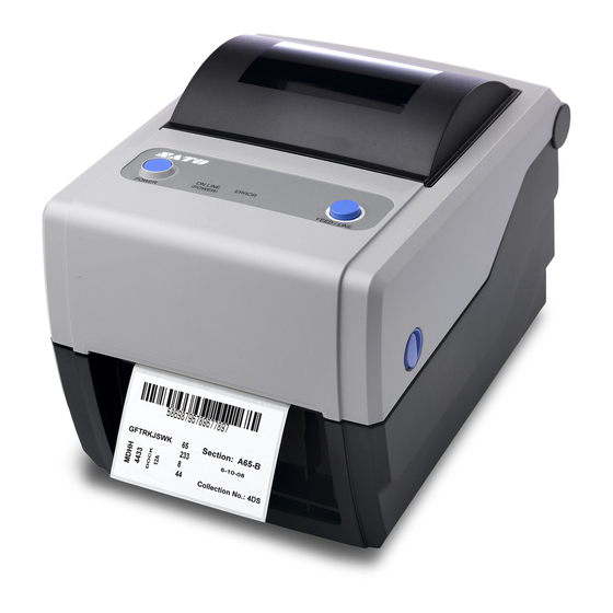
Section 1: Introduction 1.3 PARTS IDENTIFICATION Front view Operator panel ERROR LED indicator It consists of two contact buttons and two The LED lights or blinks red when an error is LED indicators (green and red). detected in the printer. During printer configuration setting, the Top cover ERROR indicator responses in conjunction... - Page 8 Section 1: Introduction 1.3 PARTS IDENTIFICATION (cont’d) Back view USB and RS232C interface on-board USB and LAN interface on-board USB and IEEE interface on-board Media inlet LAN interface terminal An opening for Fan-folded media or media To connect printer to the host computer using from unwinder to feed in to the printer.
- Page 9 Section 1: Introduction 1.2 PARTS IDENTIFICATION (cont’d) Internal view when Top cover is opened CG408TT/ CG412TT CG408DT/ CG412DT Print head Media guide slide lever This component is used to print on the media. Set to meet the size of the media used.
- Page 10 Section 1: Introduction This page is intentionally left blank Page 1-6 CG4 Series Service Manual...
-
Page 11: General Specifications
Section 2: General Specifications GENERAL SPECIFICATIONS 2.1 PRINTER BASIC SPECIFICATIONS MODEL NAME CG408 DT CG412 DT CG408 TT CG412 TT PHYSICAL CHARACTERISTICS Width 179 mm (7.05”) Depth 238 mm (9.37”) Height 173 mm (6.81”) Weight 1.7 kg (3.7 lbs.) 1.9 kg (4.19 lbs.) POWER SUPPLY (AC ADAPTER) Input Voltage 100-240 V AC, +/-10%, 50/60 Hz (Full range) - Page 12 Section 2: General Specifications MODEL NAME CG408 DT/ CG408TT CG412 DT/ CG412TT MEDIA (Be sure to use media manufactured or certified by SATO) Direct Thermal / Thermal Transfer depending on print model (DT or TT) Type Roll stock or Fan-fold Wind Direction Roll stock: Face In or Face out winding Maximum outer diameter: 128 mm (5.04”) with Inner core diameter: 40 mm (1.5”)
- Page 13 Section 2: General Specifications MODEL NAME CG408 DT CG412 DT CG408 TT CG412 TT RIBBON (Be sure to use ribbon manufactured or certified by SATO) Wind Direction Face Out Winding Method Paper core Roll Diameter Maximum outer diameter: 38 mm (1.4”) Core Diameter Inner core diameter: 12.7 mm (0.5”)
- Page 14 Section 2: General Specifications MODEL NAME CG408 DT CG412 DT CG408 TT CG412 TT SELF-DIAGNOSIS Cover Open Detection Cover Open Detection Paper End Detection Paper Detection Test Print Test Print Cutter error (Only available if installed) Ribbon end Detection Cutter error (Only available if installed) CHARACTER FONT CAPABILITIES BITMAP FONTS 5 dots W x 9 dots H (Alphanumeric characters and symbols)
- Page 15 Section 2: General Specifications MODEL NAME CG408 DT CG412 DT CG408 TT CG412 TT BARCODE CAPABILITIES UPC-A/UPC-E, EAN8/13, CODE39, CODE93, CODE128, GS1-128 (UCC/EAN128), CODABAR(NW-7), ITF, Industrial 2 of 5, Matrix 2 of 5, Linear Bar Codes BOOKLAND, MSI, POSTNET, GS1 DataBar (RSS) * GS1 DataBar is new version of RSS-14.
- Page 16 Section 2: General Specifications MODEL NAME CG408 DT CG412 DT CG408 TT CG412 TT HARDWARE AND RELATED Operation keys POWER and FEED/LINE buttons ON LINE (POWER): Green LED Indicators ERROR: Red LED Built-in buzzer Buzzer • On/ off switchable buzzer (specified by command) •...
-
Page 17: Optional Accessories Specifications
Label only * Some restrictions may apply to some label types depending on the substrate, Media Type adhesive, paper size, and environment. Refer to SATO representative on the labels to be used. * Perforated liner and split liner cannot be used. - Page 18 Section 2: General Specifications This page is intentionally left blank Page 2-8 CG4 Series Service Manual...
-
Page 19: Interface Specifications
Section 3: Interface Specifications INTERFACE SPECIFICATIONS This section presents the interface types and their specifications for the CG4 Series printers. These specifications include detailed information to assist in the selection of the most appropriate method for the printer to interface with the host. The following information is presented in this section: •... -
Page 20: Rs232C Serial Interface
Section 3: Interface Specifications 3.2 RS232C SERIAL INTERFACE 3.2.1 Basic Specifications of RS-232C Serial Interface This interface complies with the RS-232C standard. Interface connector DB-9S or equivalent (Male) Cable length: 5m or less Communication Use Printer configuration tool or <I2> command to setup. settings <I2>abcde Parameter... - Page 21 Section 3: Interface Specifications 3.2 RS232C SERIAL INTERFACE (cont’d) Function descriptions Function Description Baud rate setting Select the data rate (bps) for the RS232 port. Data bit length Sets the printer to receive either 7 or 8 bits of data for each byte transmitted. Parity setting Selects the type of parity used for error detection.
- Page 22 Section 3: Interface Specifications 3.2 RS232C HIGH SPEED SERIAL INTERFACE (cont’d) 3.2.2 Ready/Busy This protocol controls the reception of print data only by the control of hardware signal. Use the command <I2> to toggle between single item buffer and multi item buffer. When the print data (STX ESC+”A”~ ESC+”Z”...
- Page 23 Section 3: Interface Specifications 3.2 RS232C HIGH SPEED SERIAL INTERFACE (cont’d) Timing Chart (Single item buffer) (1) Normal process Press the Press the Power ON FEED/LINE button FEED/LINE button Printer side Initial STX..ETX(1) ETX(2) …….. Online Online Offline Printer status Receiving/Analysis/Editing(1) Receiving/Analysis/Editing(2) Print(2)
-
Page 24: Pin Assignments
Section 3: Interface Specifications 3.2 RS232C HIGH SPEED SERIAL INTERFACE (cont’d) 3.2.3 X-ON/X-OFF This transmission protocol informs the host if the printer is ready to receive data, by sending the “XON” (Hex 11H) or “XOFF” (Hex 13H) code. When the print data (STX ESC+”A”~ ESC+”Z” ETX) is sent from the host in the conditions below, received data may be incorrect. - Page 25 Section 3: Interface Specifications 3.2 RS232C HIGH SPEED SERIAL INTERFACE (cont’d) 3.2.4 Return Status (STATUS 3 and Protocol for Driver (STATUS 4)) The purpose of these protocols is to control printer status on the host side. With the request command from the host, the status is returned from the printer.
-
Page 26: Ieee 1284 Parallel Interface
Use Printer configuration tool or <DI> command. <DI>a Parameter Item Value Decription Interface IEEE1284 Maximum receive buffer capacity Buffer near full occurred Remaining 0.25MB Buffer near full released Remaining 0.5MB DeviceID CG408 “MFG:SATO;CMD:PCL,MPL;MDL:CG408;” CG412 “MFG:SATO;CMD:PCL,MPL;MDL:CG412;” Page 3-8 CG4 Series Service Manual... - Page 27 Section 3: Interface Specifications 3.3 IEEE 1284 PARALLEL INTERFACE (cont’d) 3.3.2 Pin Assignments Pin assignment of each signal for the Centronics standard (Compatible Mode) is as follows. Note that the connection of the IEEE1284standard complies with the IEEE1284-B standard. PIN No. Signal PIN No.
- Page 28 Section 3: Interface Specifications 3.3 IEEE 1284 PARALLEL INTERFACE (cont’d) 3.3.3 Input/Output Signals The details of each signal line for the Centronics standard (Compatible Mode) are as follows. Note that each signal line complies with the IEEE1284 standard. Signal Description STROBE Input Synchronization signal that requires low active pulse to read...
- Page 29 Section 3: Interface Specifications 3.3 IEEE 1284 PARALLEL INTERFACE (cont’d) Timing Chart (Single item buffer) 1) Normal process Press FEED/LINE Press FEED/LINE Power ON Printer side Initial ESC A…ESC Z(1) ESC A……ESC Z(2) DATA STROBE BUSY SELECT FAULT Offline Online Online Printer status Receiving/Analysis/...
- Page 30 Section 3: Interface Specifications 3.3 IEEE 1284 PARALLEL INTERFACE (cont’d) Timing Chart (Multi item buffer) 1) Normal process Receive buffer Power ON Receive buffer Press FEED/LINE Press FEED/LINE near full occurred near full release Printer side Initial … … ESC A…ESC Z(1) DATA STROBE BUSY...
-
Page 31: Universal Serial Bus (Usb) Interface
Section 3: Interface Specifications 3.4 UNIVERSAL SERIAL BUS (USB) INTERFACE This printer supports the USB 2.0-compliant interface and the transfer rate at 12.5 Mbits/second. 3.4.1 Basic Specifications of USB interface The USB interface is available with all three types of boards. Interface connector Series B plug Cable length: 5m or less (Twisted Pair Shielded) - Page 32 Section 3: Interface Specifications 3.4 UNIVERSAL SERIAL BUS (USB) INTERFACE (cont’d) 3.4.3 Host Computer Settings Installation of USB Standard Print Support It is necessary to install the USB driver in addition to the printer driver to perform print operation via the USB port.
-
Page 33: Local Area Network (Lan) Ethernet
Section 3: Interface Specifications 3.5 LOCAL AREA NETWORK (LAN) ETHERNET 3.5.1 Basic Specifications of LAN A Local Area Network (LAN) interface requires a driver shipped with each printer that has the interface installed. The driver must be loaded on the host computer and configured to run one of the supported network protocols using a 10/100BaseT LAN connection. - Page 34 Section 3: Interface Specifications 3.5 LOCAL AREA NETWORK (LAN) ETHERNET (cont’d) Communication The following settings can be configured via the Printer configuration tool or com- configuration mands. Item Command Setting range LAN mode <I3> Protocol for driver (STATUS4) cyclic response mode * Protocol for driver (STATUS4) ENQ response mode * STATUS3 *...
- Page 35 Section 3: Interface Specifications 3.5 LOCAL AREA NETWORK (LAN) ETHERNET (cont’d) 3.5.3 TCP/IP Specifications In TCP/IP protocol environment, LPD and FTP are provided for printing. TELNET is provided for the setup of various variables, and ARP, RARP and BOOTP/DHCP for the setup of IP address are available. In socket connection, the printing operation and the status are monitored.
- Page 36 <TELNET command example> In MS-DOS command prompt, type in [TELNET xxx.xxx.xxx.xxx (IP address)] and enter user name and password to advance to the display below. SATO PRINTER ModelName TELNET server. Copyright 2006(C) SATO Corporation. login: root ‘root’ user needs password to login password: User ‘root’...
- Page 37 Notes 1) For the detailed On-board LAN interface settings, refer to the included [Setup Guide] and the Network Utility of [SATO Accessory CD-ROM]. 2) To open/close Print data port (Port1024), Status port (Port1025) or Sending/Receiving port (Port9100), make sure to close and open the port at intervals of approximately 150ms to 200ms. If you don't have enough time from closing to opening the port, it may result in double connection.
- Page 38 Section 3: Interface Specifications This page is intentionally left blank Page 3-20 CG4 Series Service Manual...
-
Page 39: Operation And Configuration
Before using the printer, it is best to read this manual thoroughly. Otherwise, you may disturb default settings on which the instructional procedures in this manual are based. Most of the printer’s settings are controlled via standard SBPL commands or by using the provided SATO Utilities Tool application. -
Page 40: Operator Panel
Section 4: Operation and Configuration 4.1 OPERATOR PANEL The operator panel located on the top front, consists of two buttons and two LED indicators (red and green). • POWER button Press POWER button to turn on or off the printer. Press POWER button together with FEED/LINE button to enter various operating modes. -
Page 41: Operating Modes
Section 4: Operation and Configuration 4.2 OPERATING MODES You can set the printer in any of the following modes: Normal mode (including Online/Offline modes) User Test print mode Factory Test print mode Operation Setting mode: • Program download mode • Font download mode •... -
Page 42: Section 4: Operation And Configuration
Section 4: Operation and Configuration 4.2 OPERATING MODES (cont’d) The following flow chart provides a clear summary of each of the modes and its access method. LED indicator responses Procedures Buzzer Operating Mode ON LINE (POWER) ERROR Power off Press POWER button Printer Start up Red light... - Page 43 Section 4: Operation and Configuration 4.2 OPERATING MODES (cont’d) LED indicator responses Procedures Operating Mode ON LINE (POWER) ERROR Buzzer Power off Keep holding FEED/LINE With top cover open, button until the desired while pressing mode lighting pattern is FEED/LINE button, shown.
-
Page 44: User Test Print Mode
Section 4: Operation and Configuration 4.3 USER TEST PRINT MODE This mode produces test labels for diagnostic purposes. Preparation: Make sure the media or ribbon (if required) are properly loaded in the printer. ON LINE (POWER) ERROR Procedures Printer status Buzzer indicator indicator... - Page 45 [4.53”] (Pitch), Standard. First print-out (Settings) Print Item Contents of the print data Model Printer model name CG408TT(*), CG412TT(*) CG408DT, CG412DT *: “T” is printed for thermal transfer print. “D” is printed for direct thermal print. Offset Offset value (Vertical and (H)±300 (V)±300 DOT...
- Page 46 Section 4: Operation and Configuration 4.3 USER TEST PRINT MODE (cont’d) Second print-out (Protocol code setting values) Print Item NULL OFFLINE AUTO ONLINE ZERO SLASH Zero slash EURO Euro code Third print-out (Interface) USB and RS-232C interface on board Print Item Contents of the print data Selected Interface In-use interface...
- Page 47 Section 4: Operation and Configuration 4.3 USER TEST PRINT MODE (cont’d) USB and IEEE 1284 interface on board Print Item Contents of the print data Selected Interface In-use interface USB / IEEE1284 Interface 1 Interface 1 Buffer Type Buffer type Multi Protocol Protocol...
-
Page 48: Factory Test Print Mode
Section 4: Operation and Configuration 4.4 FACTORY TEST PRINT MODE This mode produces test labels for diagnostic purposes. Preparation: Make sure the media or ribbon (if required) are properly loaded in the printer. ON LINE (POWER) ERROR Procedures Printer status Buzzer indicator indicator... - Page 49 [4.53”] (Pitch), Standard. First print-out (Settings) Print Item Contents of the print data Model Printer model name CG408TT(*), CG412TT(*) CG408DT, CG412DT *: “T” is printed for thermal transfer print. “D” is printed for direct thermal print. Firm Ver Printer F/W version **.**.**.**...
- Page 50 4.4 FACTORY TEST PRINT MODE (cont’d) Second print-out (Settings) Print Item Contents of the print data Model Printer model name CG408TT(*), CG412TT(*) CG408DT, CG412DT *: “T” is printed for thermal transfer print. “D” is printed for direct thermal print. Offset Base reference correction (H)±300 (V)±300 DOT...
-
Page 51: Operation Setting Mode
Section 4: Operation and Configuration 4.5 OPERATION SETTING MODE The operation setting mode enables further selection of the functions of the printer. These are: • Program download mode • Font download mode • Default setting mode • HEX dump mode •... - Page 52 Section 4: Operation and Configuration OPERATION SETTING MODE (cont’d) ON LINE (POWER) ERROR Procedures Printer status Buzzer indicator indicator Press the FEED/LINE Program Download Three Mode short button repeatedly to Blinking green light beeps select different operation FEED/LINE setting mode cyclically. Font Download Mode Red light FEED/LINE...
-
Page 53: Program Download Mode
Section 4: Operation and Configuration OPERATION SETTING MODE (cont’d) Notes: • Press the FEED/LINE button to select the desired function, and then execute the selected function by pressing and holding the FEED/LINE button for more than 3 seconds. • When the desired interface is selected, this setting will be valid after you restart the printer. •... - Page 54 Section 4: Operation and Configuration 4.6 PROGRAM DOWNLOAD MODE (cont’d) CAUTION: • Downloading firmware will initialize all the previous settings (set by Utilities tool application or by commands). Write down its setting details or keep a copy of FACTORY TEST PRINT for your information in case you wish to maintain the same settings in the future.
-
Page 55: Font Download Mode
Section 4: Operation and Configuration 4.7 FONT DOWNLOAD MODE In this mode, the printer is set to download fonts from the host computer. Remember to set the printer to the correct active interface to be used for the data transfer. ON LINE (POWER) ERROR Status of printer in Font Download Mode... -
Page 56: Default Setting Mode
Section 4: Operation and Configuration 4.8 DEFAULT SETTING MODE When default setting mode is selected and executed in Operation Setting mode (refer to Section 4.5 Operation Setting Mode ), the printer will reset to the default setting (factory preset) as listed below. Items to be reset Default value Offset (V, H) -
Page 57: Boot Download Mode
Section 4: Operation and Configuration 4.10 BOOT DOWNLOAD MODE In this boot download mode, the operator can download and replace the entire boot section of the firmware in the Flash ROM memory. This is a critical mode meant only to be handled by experienced operators. Avoid using this mode if you are not clear about its function. -
Page 58: Error Occurrence While Downloading
Section 4: Operation and Configuration 4.11 ERROR OCCURRENCE WHILE DOWNLOADING The following are the possible causes of errors in program/font download. (1) The flash ROM may be in a state that fails to permit data being written to it. (2) Incorrect data are received while transferring downloaded data. 4.11.1 Operation Status when having an Error in Downloading Process The ERROR indicator and buzzer response when having an error in downloading process are as follows. -
Page 59: Factory Clear Mode
Section 4: Operation and Configuration 4.12 FACTORY CLEAR MODE The printer has integrated counters to measure the accumulative activity of some features. These includes head counter, cutter counter and all counter. You have to reset the measurement of these counters to zero whenever the counterpart has been replaced. Selection and activation of the above Factory Clear modes are as shown below. - Page 60 Section 4: Operation and Configuration 4.12 FACTORY CLEAR MODE (cont’d) 4.12.1 Contents of Factory Clear (Head Counter Clear) Executing factory clear (Head counter clear) will set the following items to factory default. Items to be initialized Setting value Head counter 1 0.0Km Head counter 2 0.0Km...
- Page 61 Section 4: Operation and Configuration 4.12 FACTORY CLEAR MODE (cont’d) Items to be initialized Setting value Initial Feed Disabled Auto Feed Disabled Operation mode Continuous - (No setting) Tear-Off - (No setting) Cutter Mode 1 (Head position) Dispenser Mode 1 (Head position) Nonsepa (Linerless) Mode 2 (Tear off position) Interface...
-
Page 62: Factory Adjustment Mode
Section 4: Operation and Configuration 4.13 FACTORY ADJUSTMENT MODE The I-Mark and Gap sensor threshold levels are adjusted automatically in the Factory Adjustment mode. In this automatic adjustment, I-Mark and GAP sensors will be adjusted continuously. Proceed the following instructions to perform the adjustment. Preparation: Load in the test labels compatible with I-Mark and Gap sensors. - Page 63 Section 4: Operation and Configuration 4.13 FACTORY ADJUSTMENT MODE (cont’d) ON LINE (POWER) ERROR Procedures Printer status Buzzer indicator indicator The printer will feed at Press the FEED/LINE least 3 labels to adjust button to execute the the Gap sensor auto- Green light Gap sensor output matically.
- Page 64 These output data are printed in three parts, each with the printing area of 115 mm [3.54”] (Width) x 115 mm [3.54”] (Pitch), Standard. First print-out Print Item Contents of the print data CG408TT(*), CG412TT(*) CG408DT, CG412DT *: “T” is printed for thermal Model Printer model name transfer print. “D” is printed for direct thermal print.
- Page 65 Section 4: Operation and Configuration 4.13 FACTORY ADJUSTMENT MODE (CONT’D) Third print-out Print Item Contents of the print data CG408TT(*), CG412TT(*) CG408DT, CG412DT *: “T” is printed for thermal Model Printer model name transfer print. “D” is printed for direct thermal print.
-
Page 66: Factory Usb Interface Mode
Section 4: Operation and Configuration 4.14 FACTORY USB INTERFACE MODE This mode enables the printer to connect multiple printers to a single USB port of the host computer. ON LINE (POWER) ERROR Procedures Printer status Buzzer indicator indicator With top cover open, while Printer start-up pressing the FEED/LINE button, press and release... -
Page 67: Factory Usb Boot Download Mode
Section 4: Operation and Configuration 4.15 FACTORY USB BOOT DOWNLOAD MODE This mode enables the printer to connect multiple printers to a single USB port of the host computer. ON LINE (POWER) ERROR Procedures Printer status Buzzer indicator indicator With top cover open, while Printer start-up pressing the FEED/LINE button, press and release... -
Page 68: Printer Configurations Setting
Section 4: Operation and Configuration 4.16 PRINTER CONFIGURATIONS SETTING You can set the printer configuration by sending SBPL commands from the host computer or by using the Utilities Tool application provided (SATO Accessory CD-ROM). Category Setting item Setting contents Operation mode... - Page 69 *1. Available for USB+RS-232C specification only. *2. Available for USB+LAN specification only. *3. Use SATO port or Port 9100 when sending print request from the printer driver. *4. Available for IEEE1284+USB specification only. *5. The printer will restart in specified mode.
- Page 70 Section 4: Operation and Configuration This page is intentionally left blank Page 4-32 CG4 Series Service Manual...
-
Page 71: Troubleshooting
Section 5: Troubleshooting TROUBLESHOOTING If you are unable to produce printouts on the CG4 Series printer, use this section to make sure the basics have been checked, before deciding you are unable to proceed any further. This section is divided into four parts: •... -
Page 72: Error Signal Troubleshooting
Section 5: Troubleshooting 5.1 ERROR SIGNAL TROUBLESHOOTING The ON LINE (POWER) and ERROR indicators light or flash in different colors and patterns listed below to alert user that an error has occurred on the printer. [Indicator sequence (as shown from left to right): Off, Red light, Green light]... -
Page 73: Section 5: Troubleshooting
Section 5: Troubleshooting 5.1 ERROR SIGNAL TROUBLESHOOTING (cont'd) ON LINE ERROR Contents (POWER) Buzzer Causes Corrective Actions Minor error Cover open Blinking red 3 short 1) Cover is not closed 1) Close the cover. beeps properly. sound Sensor error 1) Wrong sensor level. 1) Level adjustment. -
Page 74: Troubleshooting Flowchart
Section 5: Troubleshooting 5.2 TROUBLESHOOTING FLOWCHART When a problem occurs, the solution can be easily traced using the following troubleshooting flowcharts in this section. These flowcharts are categorised by different problems and its symptoms, probable causes, and suggested corrective actions. 5.2.1 Power Problem Category Symptoms... - Page 75 Section 5: Troubleshooting 5.2 TROUBLESHOOTING FLOWCHART (cont’d) 5.2.2 Feed Problems Category Symptoms Causes Remedy Maintenance Printer Is media Set media does not Feed loading OK? correctly feed media Set the sensor Is sensor correctly by type selection Utility Tool setting Check the Replace I-Mark connection of...
- Page 76 Section 5: Troubleshooting 5.2 TROUBLESHOOTING FLOWCHART (cont’d) 5.2.2 Feed Problems (cont’d) Category Symptoms Causes Remedy Maintenance Media does Set the sensor Is sensor not stop at Feed correctly by type selection the speci- Utility Tool setting fied position Replace I-Mark Is sensor sensor ASSY, Adjust I-Mark &...
- Page 77 Section 5: Troubleshooting 5.2 TROUBLESHOOTING FLOWCHART (cont’d) 5.2.3 Print Problems Category Symptoms Causes Remedy Maintenance Is interface No printing Connect Print cable connection motion interface cable Is data input Re-entry data Check the Is board connection of connection Main PCB Check Feeding Replace condition...
- Page 78 Section 5: Troubleshooting 5.2 TROUBLESHOOTING FLOWCHART (cont’d) 5.2.3 Print Problems (cont’d) Category Symptoms Causes Remedy Maintenance Print is very Set the Print Print dark darkness Refer to 6.7 Print Darkness Adjustment Is print Set the Print Print is very darkness darkness light setting OK?
- Page 79 Section 5: Troubleshooting 5.2 TROUBLESHOOTING FLOWCHART (cont’d) 5.2.3 Print Problems (cont’d) Category Symptoms Causes Remedy Maintenance Misaligned Replace I-Mark Is data input print start Print Re-entry data sensor ASSY & position (vertical GAP sensor direction) ASSY Refer to Adjust Pitch 7.9 I-Mark/Gap Offset Sensor...
- Page 80 Section 5: Troubleshooting 5.2 TROUBLESHOOTING FLOWCHART (cont’d) 5.2.4 Media Problem Category Symptoms Causes Remedy Maintenance Is media Media Set media and Media loading OK? meandering media guide correctly Is platen Clean roller clean? platen roller Replace platen roller Refer to 7.2 Platen Roller Replacement 5.2.5 Keypad or Scanner Unit Problem (Optional)
- Page 81 Section 5: Troubleshooting 5.2 TROUBLESHOOTING FLOWCHART (cont’d) 5.2.6 Cutter Problem (optional) Category Symptoms Causes Remedy Maintenance Cutter does Set to Cutter Is cutter mode Cutter not move Mode correctly set? (optional) Refer to 4.16 Printer Configura- tions Setting Press the FEED/LINE button Is cutter to move cutter...
- Page 82 Section 5: Troubleshooting 5.2 TROUBLESHOOTING FLOWCHART (cont’d) 5.2.7 Label Dispenser Problem (optional) Category Symptoms Causes Remedy Maintenance Labels Label Set dispenser Is Dispenser are not dispenser unit correctly unit correctly dispensed set? (optional) Clean the Is Dispensing Dispensing roller roller clean? and Platen roller Replace Dispensing roller...
- Page 83 Section 5: Troubleshooting 5.2 TROUBLESHOOTING FLOWCHART (cont’d) 5.2.8 Linerless (Non Sepa) Problem (Optional) Category Symptoms Causes Remedy Maintenance Labels Is Linerless Set Linerless Linerless are not (Non sepa) (Non sepa) (Non sepa) unit correctly dispensed unit correctly set? (optional) Clean the Linerless platen Linerless platen roller clean?
-
Page 84: Interface Troubleshooting
Click on System within the new window. Click on the Device Manager tab. Ensure that the View Device By Type is checked. Scroll to SATO-USB Device and ensure that errors do not exist. Reinstall as required. Reboot the PC and the printer. RS232 SERIAL INTERFACE TROUBLESHOOTING STEP Ensure the correct interface module is correctly installed. -
Page 85: Test Print Troubleshooting
Section 5: Troubleshooting 5.3 INTERFACE TROUBLESHOOTING (Cont’d) PARALLEL INTERFACE TROUBLESHOOTING STEP Ensure the interface module is correctly installed. Run self-test to verify. Ensure the printer cable is connected to the appropriate LPT port on the host computer. If using a Windows printer driver, ensure the correct port is selected. - Page 86 Section 5: Troubleshooting This page is left blank intentionally Page 5-16 CG4 Series Service Manual...
-
Page 87: Checks And Adjustment Procedures
Section 6: Checks and Adjustment Procedures CHECKS AND ADJUSTMENT PROCEDURES This section provides instructions for electrical and mechanical adjustments to the printer. Regular maintenance in making adjustments to reset the printer to factory specifications will ensure optimum performance of your printer. The Adjustment Procedure describe in this section are as follows. -
Page 88: Checking The Power Supply
Section 6: Checks and Adjustment Procedures 6.1 CHECKING THE POWER SUPPLY This checking procedure enables checking various direct current voltages of the MAIN Printed Circuit Board ( PCB ). These checking activities require the use of a multimeter. Switch off the printer. Remove the Bottom Housing Cover as explained in Section 7.3 Removal of the Bottom Housing cover . -
Page 89: Automatic Adjustment Of I-Mark And Gap Sensor Outputs
Section 6: Checks and Adjustment Procedures 6.1 CHECKING THE POWER SUPPLY (cont’d) Diagnosis and Remedy: If the measurement at Test Point 5A could not meet the +19.0 V criteria, turn off the printer and remove the power cable from the connector. Then, connect the probe to Point F [+] and Point G [-] on the DC board to measure the voltage of power source itself. -
Page 90: Ribbon Tension Adjustment (For Cg408Tt, Cg412Tt Only)
Section 6: Checks and Adjustment Procedures 6.3 SENSOR CHECKS (cont’d) 6.3.2 Top Cover Open Sensor Check Press POWER button to turn on the printer. Lift the Top Cover to generate a Top Cover open error, the ERROR indicator displayed red. If the sensor is faulty, refer to Section 7.7 Top Cover Open Sensor Replacement of this manual for replacement instructions. -
Page 91: Pitch Position Adjustment
Section 6: Checks and Adjustment Procedures 6.5 PITCH POSITION ADJUSTMENT The label Pitch is the distance from the leading edge (the edge that comes out of the printer first) of a label and the leading edge of the next label. The leading edge position of the label can be adjusted relative to the print head. -
Page 92: Offset Position Adjustment
Adjustment - Adjustment +99 dots -99 dots In addition to the above setting, the Offset position can also be adjusted by using SATO Utilities Tool application or by sending command <PO> from the host. Page 6-6 CG4 Series Service Manual... -
Page 93: Print Darkness Adjustment
Section 6: Checks and Adjustment Procedures 6.7 PRINT DARKNESS ADJUSTMENT This feature allows the print darkness to be adjusted, thus affecting the quality and scannability of printed content. This adjustment must be made through host to printer interface connection, by sending command. The print darkness can be adjusted within the range of 1 to 5. - Page 94 Section 6: Checks and Adjustment Procedures This page is left blank intentionally Page 6-8 CG4 Series Service Manual...
-
Page 95: Replacement Procedures
Section 7: Replacement Procedures REPLACEMENT PROCEDURES This unit provides in-depth instruction on all primary component and assembly replacement, in addition to most secondary components. Be sure to observe all the precautions or warning notes. The Replacement Procedure describe in this section are as follows. •... -
Page 96: Print Head Replacement
Section 7: Replacement Procedures 7.1 PRINT HEAD REPLACEMENT If the print head becomes damaged or worn, it can be easily removed and replaced without having to make critical adjustments. Please wear protective gloves to avoid contaminating the sensitive print head surface. Before replacing the print head, check the head counter values by printing a test pattern. - Page 97 Section 7: Replacement Procedures 7.1 PRINT HEAD REPLACEMENT (cont’d) 7.1.2 Print Head Replacement (For CG408 TT and CG412 TT Thermal transfer printer) Ensure the printer is turned off, and remove the power cable. Lift the Top Cover . Pull the lever on the middle of the ribbon unit downward to pull out the ribbon unit .
-
Page 98: Platen Roller Replacement
Section 7: Replacement Procedures 7.1 PRINT HEAD REPLACEMENT (cont’d) Align the two circular recess of the print head bracket to Hooks the two springs attached to the top cover frame . At the same time, fix the fulcrum shaft of the print head bracket to the hooks . -
Page 99: Removal Of The Bottom Housing Cover
Section 7: Replacement Procedures 7.3 REMOVAL OF THE BOTTOM HOUSING COVER Make sure the printer is powered off and disconnect the power cable and interface cable. screw x 3 From the base of the printer, remove three screws (circled) as shown. CAUTION: Ensure not to scrape the window portion when the printer is turned over. -
Page 100: Dc Power Terminal Board Replacement
Section 7: Replacement Procedures 7.4 DC POWER TERMINAL BOARD REPLACEMENT Remove the Bottom Housing Cover as explained in the earlier Section 7.3 Removal of the Bottom Housing cover . Press to release the catch of the Power cable connector and disconnect the connector from the MAIN Printed Circuit Board (PCB) as shown. -
Page 101: Main Circuit Board Replacement
Section 7: Replacement Procedures 7.5 MAIN CIRCUIT BOARD REPLACEMENT The main circuit board is the primary brain-center for all printer activities. Circuit boards generally have long lives due to the lack of moving parts. So if a circuit board becomes defective, it is usually due to a negative external condition. -
Page 102: Operator Panel (Kb) Board Replacement
Section 7: Replacement Procedures 7.6 OPERATOR PANEL (KB) BOARD REPLACEMENT This circuit board provides the user interaction functionality via Operator buttons. 7.6.1 Operator Panel Board Replacement ( CG408 DT and CG412 DT Direct Thermal printer) Ensure the printer is turned off, and remove the power cable. - Page 103 Section 7: Replacement Procedures 7.6 OPERATOR PANEL (KB) BOARD REPLACEMENT (cont’d) Replace the new Operator Panel (KB) board and follow the above steps in reverse sequence, to reassemble the parts. Notes: • During replacement, ensure the two blue buttons were in the position where the tab sits in the groove.
-
Page 104: Top Cover Open Sensor Replacement
Section 7: Replacement Procedures 7.6 OPERATOR PANEL (KB) BOARD REPLACEMENT (cont’d) Replace the new Operator Panel (KB) board and follow the above steps in reverse sequence, to reassemble the parts. Notes: • During replacement, ensure the two blue buttons were in the position where the tab sits in the groove. -
Page 105: Stepper Motor Replacement
Section 7: Replacement Procedures 7.8 STEPPER MOTOR REPLACEMENT Remove the Bottom Housing Cover as explained in the earlier Section 7.3 Removal of the Bottom Housing cover . MOTOR cable assy Remove three screws (circled) securing the Stepper motor assembly to the printer. Disconnect the MOTOR cable assy from the MAIN PCB . -
Page 106: I-Mark/Gap Sensor Replacement
Section 7: Replacement Procedures 7.9 I-MARK/GAP SENSOR REPLACEMENT The Gap sensor is of a transmit/ receive variety. The transmit and receive sensors are mounted separately on the left media guide. The I-Mark/Gap sensor may need replacement if cleaning or adjustment of sensor sensitivity does not improve their functionality. - Page 107 Section 7: Replacement Procedures 7.9 I-MARK/GAP SENSOR REPLACEMENT (cont’d) Remove the Upper Gap sensor board as indicated and disconnect the attached cable connector . Replace the new Upper Gap sensor board . Remove the screw (circled) securing the I-Mark/Gap I-Mark/Gap sensor sensor board assy to the left Media guide .
-
Page 108: Ribbon End Sensor Replacement
Section 7: Replacement Procedures 7.10 RIBBON END SENSOR REPLACEMENT (Only for CG408 TT and CG412 TT Thermal transfer printer) Ensure the printer is turned off, and remove the power cable. Lift the Top Cover . Pull the lever on the middle of the ribbon unit downward to pull out the ribbon unit . -
Page 109: Torque Limiter (Supply Unit) Replacement
Section 7: Replacement Procedures 7.11 TORQUE LIMITER (SUPPLY UNIT) REPLACEMENT (Only for CG408 TT and CG412 TT Thermal transfer printer) Remove the Frame cover of the Ribbon unit as mentioned in Section 7.10 Ribbon End Sensor Replacement above. Torque limiter assembly Follow step 1 to 4 to remove the Frame cover . -
Page 110: Torque Limiter (Ribbon Wind-Up Unit) Replacement
Section 7: Replacement Procedures 7.12 TORQUE LIMITER (RIBBON WIND-UP UNIT) REPLACEMENT (Only for CG408 TT and CG412 TT Thermal transfer printer) Remove the Frame cover of the Ribbon unit as mentioned Torque limiter in Section 7.10 Ribbon End Sensor Replacement above. assembly Follow step 1 to 4 to remove the Frame cover . -
Page 111: Cutter Kit/ Board/Unit Replacement (Optional)
Section 7: Replacement Procedures 7.13 CUTTER KIT/ BOARD/UNIT REPLACEMENT (OPTIONAL) This section covers the basic mechanical procedures for replacement of the whole Cutter Kit or just the Cutter board or Cutter unit. Before replacement, check the cutter counter by printing a Factory test print. Please refer to Section for details. - Page 112 Section 7: Replacement Procedures 7.13 CUTTER KIT/ BOARD/UNIT REPLACEMENT (OPTIONAL) (cont’d) 7.13.3 Cutter unit Replacement Peel off the Anti static sheet from the Cutter unit and put it aside for latter use. Anti static sheet Remove three screws to detach the Cutter cover from the Cutter cover Cutter unit .
-
Page 113: Dispenser Kit/ Roller/ Label Sensor Replacement (Optional)
Section 7: Replacement Procedures 7.14 DISPENSER KIT/ ROLLER/ LABEL SENSOR REPLACEMENT (OPTIONAL) This section covers the basic mechanical procedures for replacement of the Dispenser Kit. 7.14.1 Dispenser kit Replacement Remove the Bottom Housing Cover as explained in the earlier Section 7.3 Removal of the Bottom Housing MAIN PCB cover . - Page 114 Section 7: Replacement Procedures 7.14 DISPENSER KIT/ ROLLER/ LABEL SENSOR REPLACEMENT (OPTIONAL) (cont’d) Remove the two e-rings from the shaft of the dispenser roller and slide to detach the dispenser roller assembly from the bracket . e-rings x 2 Keep the loose springs and e-rings aside for latter use. roller shaft spring Dispensing roller...
-
Page 115: Linerless (Non Sepa) Label Sensor Replacement (Optional)
Section 7: Replacement Procedures 7.15 LINERLESS (NON SEPA) LABEL SENSOR REPLACEMENT (OPTIONAL) This section covers the basic mechanical procedures for replacement of the Linerless (Non sepa) label sensor. Remove the Bottom Housing Cover as explained in the earlier Section 7.3 Removal of the Bottom Housing MAIN PCB cover . -
Page 116: Real Time Clock Battery Replacement (Optional)
Section 7: Replacement Procedures 7.16 REAL TIME CLOCK BATTERY REPLACEMENT (OPTIONAL) This section covers the basic mechanical procedures for replacement of the RTC Kit. Remove the Bottom Housing Cover as explained in the earlier Section 7.3 Removal of the Bottom Housing cover . MAIN PCB Disconnect the RTC kit’s cable from the RTC connector on the MAIN PCB . -
Page 117: Appendix
Section 8: Appendix APPENDIX The following information is provided: • 8.1 Optional Accessories - Cutter • 8.2 Optional Accessories - Dispenser • 8.3 Optional Accessories - Linerless (Non sepa) • 8.4 Optional Accessories - Real Time Clock (RTC) Kit • 8.5 Positions of sensors and options •... -
Page 118: Optional Accessories - Cutter
Section 8: Appendix 8.1 OPTIONAL ACCESSORIES - CUTTER 8.1.1 To install the optional Cutter screw x 3 Make sure the printer is powered off and disconnect the power cable and interface cable. From the base of the printer, remove three screws (circled) as shown. - Page 119 Section 8: Appendix 8.1 OPTIONAL ACCESSORIES - CUTTER (cont’d) From the base of the Cutter kit , secure the cutter unit to the printer with the supplied screw (circled) as shown. Cutter kit Connect the Cutter kit’s cable to the OPTION connector OPTION on the MAIN PCB .
- Page 120 Section 8: Appendix 8.1 OPTIONAL ACCESSORIES - CUTTER (cont’d) • Cutting Media with Perforation Cut prohibited zone As for media with perforation, cutting on or in front of (1mm, 0.04”) the perforated lines is prohibited . Cutting in those locations could cause the media to jam and the printer to malfunction.
-
Page 121: Optional Accessories - Dispenser
Section 8: Appendix 8.2 OPTIONAL ACCESSORIES - DISPENSER 8.2.1 To install the optional Dispenser screw x 3 Make sure the printer is powered off and disconnect the power cable and interface cable. From the base of the printer, remove three screws (circled) as shown. - Page 122 Section 8: Appendix 8.2 OPTIONAL ACCESSORIES - DISPENSER (cont’d) Attach the latches of the Dispenser kit onto the holes located below the two sides of platen roller of the printer. Close the top cover , close the Pressure bracket and turn the printer over again, with the Main PCB is facing upward.
- Page 123 Section 8: Appendix 8.2 OPTIONAL ACCESSORIES - DISPENSER (cont’d) 8.2.2 To route the label when the dispenser is installed With the power supply off, pull the cover open/close latches on both sides of the printer toward you to unlock Pressure bracket the top cover, and then open the top cover .
-
Page 124: Optional Accessories - Linerless (Non Sepa)
Section 8: Appendix 8.2 OPTIONAL ACCESSORIES - DISPENSER (cont’d) Close the top cover until it clicks into position. After turning on the label, turn on the power. The printer is online and the ON LINE (POWER) indicator lights green. Label output from here When the printer is ready, press the FEED/LINE button to output an empty label and stop at the dispenser. - Page 125 Section 8: Appendix 8.3 OPTIONAL ACCESSORIES - LINERLESS (NON SEPA) (cont’d) Turn over the printer in upright position, open the Top cover and replace the existing platen roller with the Linerless platen roller . Refer to Section 7.2 Platen Roller Replace- ment for detailed procedure.
-
Page 126: Optional Accessories - Real Time Clock (Rtc) Kit
Section 8: Appendix 8.4 OPTIONAL ACCESSORIES - REAL TIME CLOCK (RTC) KIT 8.4.1 To install the optional RTC kit screw x 3 Make sure the printer is powered off and disconnect the power cable and interface cable. From the base of the printer, remove three screws (circled) as shown. -
Page 127: Positions Of Sensors And Options
Section 8: Appendix 8.5 POSITIONS OF SENSORS AND OPTIONS 7.3mm (0.29”) 5.0mm (0.19”) I-Mark sensor 46.3mm 34.9mm Gap sensor (1.82”) (1.37”) Print head 14.5mm 20.6mm 21.1mm (0.57”) (0.81”) Tear-off/ Nonsepa(Linerless) (0.83”) Dispenser Cutter CG4 Series Service Manual Page 8-11... -
Page 128: Operation Mode Selection
Section 8: Appendix 8.6 OPERATION MODE SELECTION There are five modes of printer operation: Continuous, Tear-off, Cutter, Dispense and Linerless (Non sepa) mode. The differences are the ways in which the label and paper backing are ejected. Before printer configuration, one must determine which mode will be used. This section identifies the functional differences among the five. -
Page 129: Base Reference Point
Section 8: Appendix 8.7 BASE REFERENCE POINT The base reference point is the point at which one determines the print and cut positions. The base reference position differs, depending on the print mode or the label pitch sensor to be used. Continuous Mode I-Mark I-Mark (CX-compatible) -
Page 130: Dispenser Mode
Section 8: Appendix 8.7 BASE REFERENCE POINT (cont’d) Dispenser Mode I-Mark I-Mark (CX-compatible) Base print Base print Base print and dispense and dispense and dispense position position position • The start of I-Mark is the base print and dispense position when using the I-Mark sensor. •... -
Page 131: Paper End
Section 8: Appendix 8.8 PAPER END 8.8.1 Roll Label End When the Label End is less than 40mm (1.57”) from the end of I-Mark I-Mark Approximately 40mm (1.57”) or Media feed direction less The printer behavior when paper end is detected is as follows: •... -
Page 132: Ribbon End
Section 8: Appendix 8.8.2 Fanfold Label End Feeds 50mm I-Mark (2”) Media feed direction The printer behavior when paper end is detected is as follows: • After printing and feeding label (2) 50mm (2”), “Paper end error” will occur. • If an error occurs while printing, label (2) will be printed again after releasing the error. -
Page 133: Sato Group Of Companies
Section 9: Sato Group of Companies SATO GROUP OF COMPANIES CG4 Series Service Manual Page 9-1... -
Page 134: Sato Group Of Companies
Tel: +48-71-381-03-60 Regus Level 2, Connaught Place, Fax: +48-71-381-03-68 Bund Garden Road, Pune. 411001, India Email: info@sato.pl Tel: +91-20-4014-7747 www.sato.pl Fax: +91-20-4014-7576 Email: technical@satoasiapacific.com www.satoasiapacific.com • Latest contact information of worldwide SATO operations can be found on the Internet at www.satoworldwide.com...
Need help?
Do you have a question about the CG412DT and is the answer not in the manual?
Questions and answers