Sign In
Upload
Download
Table of Contents
Contents
Add to my manuals
Delete from my manuals
Share
URL of this page:
HTML Link:
Bookmark this page
Add
Manual will be automatically added to "My Manuals"
Print this page
×
Bookmark added
×
Added to my manuals
Manuals
Brands
SATO Manuals
Printer
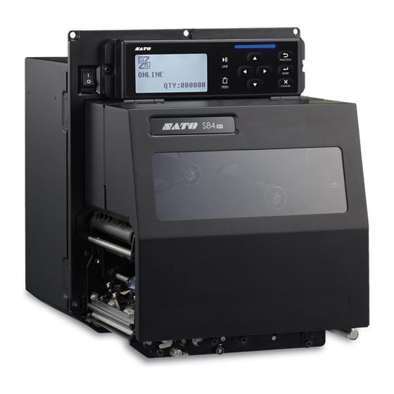
S84 ex
Service manual
SATO S84 ex Service Manual
Hide thumbs
1
2
Table Of Contents
3
4
5
6
7
8
9
10
11
12
13
14
15
16
17
18
19
20
21
22
23
24
25
26
27
28
29
30
31
32
33
34
35
36
37
38
39
40
41
42
43
44
45
46
47
48
49
50
51
52
53
54
55
56
57
58
59
60
61
62
63
64
65
66
67
68
69
70
71
72
73
74
75
76
77
78
79
80
81
82
83
84
85
86
87
88
89
90
91
92
93
94
95
96
97
98
99
100
101
102
103
104
105
106
107
108
109
110
111
112
113
114
115
116
117
118
119
120
121
122
123
124
page
of
124
Go
/
124
Contents
Table of Contents
Troubleshooting
Bookmarks
Table of Contents
Table of Contents
1 Introduction
About this Manual
Safety Precautions
Parts Identification of the Printer
Internal View with Rear Cover Opened
2 Operation and Configuration
Operating Modes
History Data Save Mode
KB Download Mode
Default Head Mode (Changing Head Density)
RFID Mode
List of Initial Values
Normal Mode
User Mode
Interface Mode
Memory Mode
Advanced Mode
Service Mode
RFID Mode
RFID User Mode
Hidden Setting Mode
Work Shift Setting Mode
3 Troubleshooting
Troubleshooting Flowchart
Power Problem
Feed Problem
Print Problem
Media Problem
4 Checking and Performing Printer Adjustments
Functional Structure of Main (CONT) PCB
Checking the Direct Current Power Voltage
Test Print Check
Adjusting the Print Position
Checking the Ribbon End Function
Checking the Head Open Error
Checking the Top Cover Open Error
Adjusting the Timing Belt Tension (Gearbox)
Adjusting the Timing Belt Tension (Ribbon Motors, Optional Ribbon Saver Motor)
5 Replacement
Removing the Housing Cover
Opening the Rear Housing Cover
Removing the Front Housing Cover
Replacing the Print Head
Replacing the Print Head (Without the Optional UHF RFID Antenna Installed)
Replacing the Print Head (with the Optional UHF RFID Antenna Installed)
Replacing the Platen Roller, Pressure Roller and Feed Roller
Replacing the Platen Roller
Replacing the Pressure Roller
Replacing the Media Feed Roller
Replacing the Media Sensor
Replacing the Main (CONT) PCB
Replacing the Operator Panel KB PCB
Replacing the Power Supply Unit
Replacing the Fan Motor
Replacing the Timing Belt
Replacing the Timing Belt of Gearbox
Replacing the Timing Belt of Ribbon Motors
Replacing the Timing Belt of Ribbon Unwind Mechanism
Replacing the Ribbon Sensor
Replacing the Ribbon End Sensor
Replacing the Head Open Sensor
Replacing the Media Sensor Assembly Open Sensor
Replacing the Top Cover Sensor
Replacing the USB PCB
Replacing the Torque Limiter for Ribbon Spindle
Replacing the Torque Limiter for Ribbon Roller
Replacing the Optional Ribbon Saver Motor Driver PCB
Replacing the Optional Ribbon Saver Sensor
Replacing the Timing Belt for the Optional Ribbon Saver
6 Installation of Options
Installation of the Optional RFID Kit
7 Appendix
Conditions for Use with Support Structure/Applicator
Media Forward Feed Force
Media Allowable Load
Media Back Feed Load Tolerance
Download and Upload Mode
Countermeasure on Firmware Download Failure
Memory Cards
Advertisement
Quick Links
1
Feed Problem
2
Print Problem
Download this manual
Service Manual
For printer model:
Table of
Contents
Previous
Page
Next
Page
1
2
3
4
5
Advertisement
Table of Contents
Need help?
Do you have a question about the S84 ex and is the answer not in the manual?
Ask a question
Questions and answers
Related Manuals for SATO S84 ex
Printer SATO S8404 Standard Spare Parts List
Sato printer parts list (23 pages)
Printer SATO S8412 Operator's Manual
Sato printers operator manual s8408, s8412, s8424 (137 pages)
Printer SATO LT408 Specifications
Sato lt408: specifications (2 pages)
Printer SATO S8408 Specifications
S84 series oem print engine (2 pages)
Printer SATO /s8408 Operator's Manual
(138 pages)
Printer SATO CG208 DT/TT User Manual
Sato cups driver for mac os x (29 pages)
Printer SATO SX4M Quick Start Manual
(23 pages)
Printer SATO S84EX Programming Reference Manual
(452 pages)
Printer SATO S86 ex Service Manual
(124 pages)
Printer SATO SG112-ex Driver Manual
(95 pages)
Printer SATO STG112 Installation Manual
Stacker (2 pages)
Printer SATO SG112 ex Programming Reference Manual
(516 pages)
Printer SATO SA408 User Manual
(56 pages)
Printer SATO CL408e/412e Frequently Asked Questions Manual
Sato owner manual printer cl408e/412e (14 pages)
Printer SATO CX Series Programming Manual
Sato printer programming manual cx series (116 pages)
Printer SATO CL408 Parts List
Sato cl408: supplementary guide (30 pages)
This manual is also suitable for:
S86 ex
Table of Contents
Save PDF
Print
Rename the bookmark
Delete bookmark?
Delete from my manuals?
Login
Sign In
OR
Sign in with Facebook
Sign in with Google
Upload manual
Upload from disk
Upload from URL


Need help?
Do you have a question about the S84 ex and is the answer not in the manual?
Questions and answers