
Related Manuals for SATO CT 408i


Summary of Contents for SATO CT 408i
- Page 1 CT4i Operator’s Manual 408i/412i /424i Read this Operator’s Manual before and during usage of the above product. Keep this document handy for future reference.
- Page 2 All rights reserved. No part of this document may be reproduced or issued to third parties in any form whatsoever without the express permission of SATO. The materials in this document are provided for general information and are subject to change without notice. SATO assumes no responsibilities for any errors that may appear.
- Page 3 This page is intentionally left blank.
-
Page 4: Table Of Contents
TABLE OF CONTENTS INTRODUCTION....................... 1-1 About this manual ......................1-2 General Description ..................... 1-3 TECHNICAL DATA......................2-1 Interface Selection ....................... 2-6 RS232C high-speed Serial Interface (25-pin) .............. 2-6 IEEE1284 Parallel Interface..................2-8 Universal Serial Bus (USB)..................2-9 Bluetooth........................2-9 Local Area Network (LAN) Ethernet................2-10 802.11G Wireless ...................... - Page 5 TROUBLESHOOTING...................... 5-1 Troubleshooting Guide....................5-2 Interface Troubleshooting .................... 5-6 Test Print Troubleshooting ................... 5-8 Hex Dump ........................5-8 Test Label Printing ....................... 5-8 MAINTENANCE........................ 6-1 Cleaning procedures ....................6-2 Adjustment Procedures....................6-3 Adjusting the Print Quality.................... 6-3 Cleaning the Print Head, Platen and Rollers..............6-4 Releasing/Replacing the Print Head ................
-
Page 6: Introduction
Unit 1: Introduction INTRODUCTION • About This Manual • General Description • Control Features CT4i Operator’s Manual... -
Page 7: About This Manual
Unit 1: Introduction ABOUT THIS MANUAL This manual is laid out consistent with the product discussed and provides all of the information required for printer installation, configuration, operation, and light maintenance. Refer to this product’s Programming Reference document for instructions on printer programming through a host system. This manual also incorporates the use of special information boxes. -
Page 8: General Description
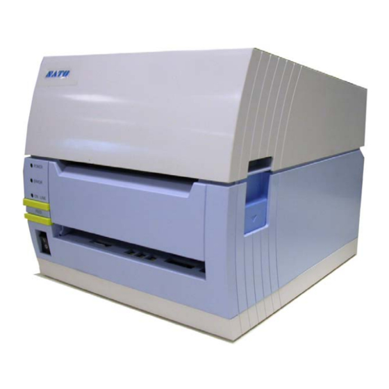
Unit 1: Introduction GENERAL DESCRIPTION The compact CT4i Series printers are designed for use in medium-volume labeling applications demanding a low footprint, crisp print quality of up to 600dpi; hardware versatility, ease of use, and great reliability. Its antibacterial chassis also positions it ideally for clinical environments. The printer’s main parts are described below. Figure 1-1, Primary Parts (Direct Thermal model) Top cover Print Head... - Page 9 Unit 1: Introduction This page is left blank intentionally. CT4i Operator’s Manual...
-
Page 10: Technical Data
Unit 2: Technical Data TECHNICAL DATA • Physical Characteristics • Environmental Specs • Power Supply • Processing • Printer Language • Interface Modules • Print • Sensing • Media • Ribbon • Regulatory Approvals • Character Font Capabilities • Barcode Capabilities CT4i Operator’s Manual... - Page 11 Flash ROM 4 Megabytes SDRAM 16 MB PRINTER LANGUAGE Standard SATO Barcode Printer Language (SBPL) 4.3 INTERFACES Either 1) USB 2.0 with RS-232C or Standard configurations 2) USB 2.0 with LAN (10BASE-T/100BASE-TX Automatic Switching) User installable Optional Inter- face Board IEEE1284, 802.11g Wireless Wi-Fi, Bluetooth...
- Page 12 Unit 2: Technical Data PRINT DT models: Direct Thermal only Method TT models: Thermal Transfer and Direct Thermal (switchable) 2, 3, 4, 5, 6 Inches Per Second (CT408i) Maximum Speed (selectable) 2, 3, 4 Inches Per Second (CT412i) 2, 3 Inches Per Second (CT424i) CT408i: 203 Dots Per Inch (8 dpmm) Resolution CT412i: 305 Dots Per Inch (12 dpmm)
-
Page 13: Character Font Capabilities
Unit 2: Technical Data REGULATORY USA/Canada UL60950-1(2001), CSA C22.2 No.60950-1-03 China CCC (GB4943-2001) CE, Nemko (EN60950-1) Singapore SS337:2001 Korea MIC, EK (only AC-Adapter applicable) FCC Part 15, Subpart B, Class B (USA/Canada) GB9254-1998, GB17625.1-2003 (China) Radiation Noise CE (EN55022, EN55024, EN61000-3-2/-3) (EU) CISPR22, CISPR24 (reference standard, Singapore) KN22, KN24 (Korea) FCC15B / FCC15C (USA/Canada) - Page 14 Unit 2: Technical Data BARCODE CAPABILITIES UPC-A/E, EAN, CODABAR, CODE39, CODE93, CODE128, UCC/EAN128, Interleaved Linear Bar Codes 2of5, Industrial 2of5, Matrix 2of5, MSI, BOOKLAND, POSTNET, EAN/UCC symbol QR code (Ver8.1), PDF417 (Ver2.4), MAXI code (Ver3.0), Data Matrix (Ver1.3) *Only Two Dimensional ECC200 is supported Ratios 1:2, 1:3, 2:5, User definable bar widths...
-
Page 15: Interface Selection
Unit 2: Technical Data INTERFACE SELECTION This unit presents the printer interface types and their specifications. These specifications include detailed information to assist in the selection of the most appropriate method for the printer to interface with the host. The five acceptable interface methods are: •... - Page 16 Unit 2: Technical Data I/O SIGNALS PIN# SIGNAL DESCRIPTION Framework Ground Output Data transferred from Printer to Host Input Data transferred from Host to Printer Output Goes to the Low state when an error occurs in the printer Input Maintained at the High state Input Maintained at the High state Signal Ground...
-
Page 17: Ieee1284 Parallel Interface
Unit 2: Technical Data IEEE1284 PARALLEL INTERFACE The parallel interface is a plug-in module that can be installed by the user and conforms to IEEE1284 specifications. It automatically detects the IEEE1284 signals and operates in the high speed mode. If the IEEE1284 signals are not detected, it will operate in the slower standard Centronics mode. -
Page 18: Universal Serial Bus (Usb)
Unit 2: Technical Data UNIVERSAL SERIAL BUS (USB) The Universal Serial Bus (USB) interface is a Plug-In Interface Module that can be installed by the user. It requires a driver (shipped with each printer that has the interface installed) that must be loaded onto the PC and configured to support USB peripherals using Windows 2000 or above. -
Page 19: Local Area Network (Lan) Ethernet
Unit 2: Technical Data LOCAL AREA NETWORK (LAN) ETHERNET A Local Area Network (LAN) interface is an optional Plug-In Interface Module that can be installed by the user. It requires a driver shipped with each printer that has the interface installed. The driver that must be loaded onto the host computer and configured to run one of the supported network protocols using a 10Base-T or 100Base-TX LAN connection. -
Page 20: G Wireless
Unit 2: Technical Data 802.11G WIRELESS The wireless print server provides easy printer interface with 802.11g Wi-Fi compliant networks free of wired connections. Each printer is shipped with an integrated driver and interface installed. The driver must be loaded onto the host computer and configured to run one of the supported protocols. SPECIFICATIONS Variable Data Rates 54, 11, 5.5, 2 and 1 Mbps... - Page 21 Unit 2: Technical Data SOFTWARE SPECIFICATIONS NOTE: In the TCP/IP protocol environment, LPD and FTP are provided for printing; TELNET for variable setup; ARP, RARP, and BOOTP/DHCP for address setup. LPD protocol complies with RFC1179 and handles the list of logical printer name as queue name such as lp, sjis, euc. In addition, a banner page can be printed by a proper setup.
-
Page 22: All Interfaces
Unit 2: Technical Data ALL INTERFACES Receive Buffer The data stream is received from the host to the printer one job at a time. This allows the software program to maintain control of the job print queue so that it can move a high priority job in front of ones of lesser importance. A multiple job buffer allows the printer to continuously receive print jobs while compiling and printing other jobs at the same time. - Page 23 Unit 2: Technical Data STATUS5 TIMING CHARTS NORMAL PROCESS (Figure 3-8a) CANCEL PROCESS (Figure 3-8b) ERROR PROCESS (Figure 3-8c) 2-14 CT4i Operator’s Manual...
- Page 24 Unit 2: Technical Data STATUS5 TIMING CHARTS PRINT PROCESS (Figure 3-8d) COMMAND PROCESS (Figure 3-8e) BCC ERROR PROCESS (Figure 3-8f) 2-15 CT4i Operator’s Manual...
- Page 25 Unit 2: Technical Data This page is intentionally left blank. 2-16 CT4i Operator’s Manual...
-
Page 26: Installation
Unit 3: Installation INSTALLATION • Unpacking & Parts Identification • Printer Installation • Operational Mode Selection • Interface Selection • Accessories Installation CT4i Operator’s Manual... -
Page 27: Overview
Unit 3: Installation OVERVIEW This section assists you in unpacking the printer from the shipping container. You will also be guided through a familiarization tour of the main parts and controls. The following information is provided herein: • Safety Precautions •... - Page 28 Unit 3: Installation SAFETY PRECAUTIONS Please read the following information carefully before installing and using the printer THE CAUTION SYMBOL Whenever the triangular Caution logo appears in this manual, pay special attention to the warning(s) cited below it. Failure to abide by the warnings may result in injury or damage to property. PRINTER PLACEMENT TIPS •...
- Page 29 Unit 3: Installation GENERAL PRECAUTIONS • When using head cleaning liquid, note that it is flam- • Do not disassemble or perform modifications to mable. Never heat it or throw it into a fire. Keep it out the printer, as this renders the product unsafe. of children’s reach to avoid accidental consumption.
-
Page 30: Unpacking & Parts Identification
Unit 3: Installation UNPACKING & PARTS IDENTIFICATION When unpacking the printer, take note of the following: The box should stay right-side up. If the printer has been stored in the Lift the printer out of the box carefully. cold, allow it to reach room temperature before turning it on. -
Page 31: Printer Installation
Unit 3: Installation PRINTER INSTALLATION This chapter provides guidance on how to station, connect, and load the printer once unpacked. Following printer setup, proceed to the next chapter for information on interface selection. SITE LOCATION • Station the printer on a solid flat surface. •... -
Page 32: Ribbon Loading
Figure 3-3b, Ribbon Loading NOTES 1. For best printing results and minimal operational problems, use only genuine SATO-approved combinations of ribbon and labels. 2. Beware of injury when lifting or closing the printer covers. 3. Remove the label and ribbon media before transporting the printer. -
Page 33: Loading Fanfold Paper
Unit 3: Installation LOADING FANFOLD PAPER Fan-folded media is fed inward from the rear, via the rear housing cover (highlighted in yellow below), but is stacked as opposed to suspended. Ribbon can be wound in or wound out. 1. Place the fanfold media behind the printer with the printing surface up. -
Page 34: Label Sensing
Unit 3: Installation LABEL SENSING The SATO CT4i uses label Gap (see-thru) as well as I-Mark sensing. The Sensor Assembly is located on the left edge of the media and is automatically positioned by the Paper Guides. Printer Label Sensor Positioning... -
Page 35: Operational Mode Selection
Unit 3: Installation OPERATIONAL MODE SELECTION There are two modes of printer operation; Dispense and Continuous. The difference between the two is the way that the label and paper backing is ejected. Before printer configuration, one must determine which mode will be used. - Page 36 Unit 3: Installation CONTINUOUS MODE TRANSMISSION SENSOR REFLECTIVE SENSOR Base Print Position TEAR-OFF MODE TRANSMISSION SENSOR REFLECTIVE SENSOR Base Print & Tear- Off Position CUTTER MODE TRANSMISSION SENSOR REFLECTIVE SENSOR Base Print Position Base Print Position Base Print & Cut Position DISPENSE MODE REFLECTIVE SENSOR...
- Page 37 Unit 3: Installation This page is intentionally left blank. 3-12 CT4i Operator’s Manual...
-
Page 38: Printer Configuration
Unit 4: Printer Configuration PRINTER CONFIGURATION • Configuration Modes • Configuration Modes • Menu Definition Tables CT4i Operator’s Manual... -
Page 39: Configuration Modes
Unit 4: Printer Configuration CONFIGURATION MODES Before using the printer, it is best to read this manual thoroughly first. Otherwise, you may disturb default settings around which the instructional procedures in this manual are based upon. The printer may be configured via the buttons and/or potentiometers located on the printer’s front panel. -
Page 40: The Rear Panel
Unit 4: Printer Configuration 4.2 THE REAR PANEL All of the printer cable connectors are located on the Rear Panel, as follows. Fanfold-label Loading Slot Remove this panel to route fanfold paper into the printer Factory installed USB + RS232C Interface Optional interface slot This interface can be selected at the time of This slot can be used to house an additional... -
Page 41: The Configuration Panel
Unit 4: Printer Configuration 4.3 THE CONFIGURATION PANEL The Configuration Panel is accessible when you lift up the top cover. The panel consists of an eight-position DIP switch, three adjustment potentiometers and a seven- segment LED Error Status display. Receptacles for connecting the optional Cutter (factory installed) are also located on this panel. - Page 42 Unit 4: Printer Configuration 4.3 DIP SWITCH SETTINGS (CONT’D) Switches 1–3: Font loading settings DSW1 DSW2 DSW3 Mode Enables the loading of fonts and/or graphics into printer Font memory for faster retrieval. Download Configuration Switch Switch 4: DT/TT Mode DSW4 Mode Switches the printer between Direct Thermal (DT) or Thermal Transfer (TT).
- Page 43 Unit 4: Printer Configuration To switch between different Barcode or Normal Head Check modes, set DSW7 to ON (for Barcode checking) or OFF (for Normal checking) and then enter the Factory Clear Mode (Head-open + ONLINE + FEED + POWER ON). Follow the flow chart below for checking the print head. Select counter to be cleared with DSW 5 and DSW6 beforehand.
- Page 44 Unit 4: Printer Configuration Switch 6: VR1 Potentiometer Adjustment mode DSW6 Mode Selects the function adjusted by VR1. If DSW6 is Off, VR1 Pitch Offset adjusts the pitch offset value over a range of +/- 3.75 mm. Print Darkness When DSW6 is On, VR1 adjusts the print darkness range. Configuration Switch Switch 7: Hex DATA Dump DSW7...
-
Page 45: Operational Modes
Unit 4: Printer Configuration 4.4 OPERATIONAL MODES The CT4i operates in 10 different modes, where each mode can by invoked via combinations of pressing the front panel buttons in a certain sequence together with DIP switch settings and print head status. The table below lists all the modes and how they can be invoked. - Page 46 Unit 4: Printer Configuration 4.4 OPERATIONAL MODES (CONT’D) Following are the standard operational functions and procedures available for selected modes. Modes not covered here are covered in the Service Manual. 4.4.1 Normal Mode The printer normally starts up in this mode. It automatically goes ONLINE and is ready for printing jobs. The following operations are possible: •...
- Page 47 Unit 4: Printer Configuration 4.4.2 User Test Print Mode (FEED + POWER ON) This mode produces test labels for diagnostic purposes. Upon entering this mode on startup, release the FEED button. A beep is then produced, and the ERROR LED will light up. When labels have been loaded properly, press the ONLINE or FEED button to start printing.
-
Page 48: Default Setting
9100.) USB: (no default settings) Bluetooth: Bluetooth mode = Status 4, PIN code = 0000000000000000, Authenti- cation mode = Authentication Level 1, ISI=0800, ISW=0012, PSI=0800, PSW=0012, Device name = SATO ONLINE PRINTER, CRC Check = Disable 4-11 CT4i Operator’s Manual... - Page 49 Unit 4: Printer Configuration 4.4.4 HEX Dump Mode (POWER ON with DSW7=ON) When turned ON in this mode, the printer will print a dump of its buffer contents received for the host. The printer awaits data feeds and when data arrives, it prints out the HEX data continuously. To terminate the HEX Dump, set DSW7 to OFF and restart the printer.
- Page 50 Unit 4: Printer Configuration 4.4.6 Program Download Mode (DSW1=ON, DSW2=OFF, DSW3=ON + POWER ON) In this mode, the printer is set to receive an application program from the host computer to download into its memory. Remember to set the printer to the correct active interface to be used for the data transfer. The status of various indicators in this mode is summarized below: Function ONLINE...
- Page 51 Unit 4: Printer Configuration 4.4.8 Errors during Font and Program Download Modes • Possible causes of errors could be that the data transfer is not correct between the printer and host, due to interface setting incompatibilities or faults in the cable. The flash ROM may be in a state that does not permit data being written to it.
- Page 52 Unit 4: Printer Configuration During the process, the following LED and Buzzer states may be observed: Function ONLINE ERROR BUZZER Display During download mode 1 beep Wait to receive data During data transfer 1 beep (start of data transfer) Data Editing FLASH ROM Clear Writing to FLASH ROM Download completed...
-
Page 53: Adjustment Of Reference Print Position
Unit 4: Printer Configuration 4.5 ADJUSTMENT OF REFERENCE PRINT POSITION You can use potentiometer VR4 for adjusting the offset (label stop position) by +/- 3.75 mm, as shown below. Adjustment of Reference Position for Printing Head Reference position Label feed direction Adjustment zero Adjustment... - Page 54 Unit 4: Printer Configuration 4.6 ADJUSTMENT OF STOP POSITION FOR CUTTER, PEEL OFF AND TEAR-OFF MODES You can use potentiometer VR1 (with DSW set to OFF) for adjusting the label stop position when options such as Cutter, Dispenser, Tear-off, etc, are installed. Adjustment range is by +/- 3.75 mm, as shown below.
-
Page 55: Potentiometer Adjustments
Unit 4: Printer Configuration 4.7 POTENTIOMETER ADJUSTMENTS Print Darkness A fine adjustment for PRINT DARKNESS can be made using potentiometer VR1 on the Front Operator Panel. It provides a continuous range of adjustment, allowing you to make precise changes. Turning VR1 clockwise will make the print darker, and counterclockwise will make it lighter. - Page 56 Unit 4: Printer Configuration 4.8 DATA DUMP DIAGNOSTIC LABEL The contents of the printer buffer can be examined using the DATA Dump mode. This printout labels each line of the received data in the left hand column, the data in the middle column followed by the same data in ASCII format in the right-hand column.
-
Page 57: Printing Test Labels
Unit 4: Printer Configuration 4.9 PRINTING TEST LABELS 1. The User Test Label prints the current default settings of the printer. 2. Press the FEED button while turning the power ON. 3. When the printer beeps, release the FEED button. 4. -
Page 58: Printing Factory/Service Test Prints
Unit 4: Printer Configuration 4.10 PRINTING FACTORY/SERVICE TEST PRINTS The Factory/Service Test Label prints the internal operating parameters of the printer. 1. Release the print head. (see “Releasing/Replacing the Print Head on page 4-4). 2. Press the LINE and FEED buttons while turning the printer ON. 3. -
Page 59: Troubleshooting
Unit 5: Troubleshooting TROUBLESHOOTING • Troubleshooting Guide • Interface Troubleshooting • Test Print Troubleshooting CT4i Operator’s Manual... -
Page 60: Troubleshooting Guide
3 Beeps Sensor error 1) Adjust sensor level Blink 3 Beeps Cutter error Connect cutter (optional item) properly or consult your SATO dealer Program Error Resend data to the printer 3 Beeps Ribbon End Check ribbon loading and/or load a new ribbon roll (TT model... - Page 61 Unit 5: Troubleshooting Display BUZZER ERROR CONDITION CORRECTIVE ACTION ERROR blinks No beep Low Battery level Check the battery level and recharge or replace the battery as necessary steady long beep Critically Low Battery Replace or recharge the battery level USB interface selected Other interface...
-
Page 62: Troubleshooting Table
Damaged or worn roller Replace rollers Poor label quality Use higher quality media Ribbon stock and media are mismatched Consult with media supplier. Use only SATO-certified media RIBBON WRINKLING Poor head alignment Adjust head balance and alignment Excessive temperature setting... - Page 63 Unit 5: Troubleshooting NO PRINTED IMAGE Print head is disconnected. Ensure print head wiring harness is connected on each end. No voltage output Replace fuse. Test power supply and replace as required Defective print head Replace print head and reset counter Damaged electronics Replace circuit board Interface problems...
-
Page 64: Interface Troubleshooting
Click on System within the new window. Click on the Device Manager tab. Ensure that the View Device By Type is checked. Scroll to SATO-USB Device and ensure that errors do not exist. Reinstall as required. Reboot the PC and the printer. CT4i Operator’s Manual... -
Page 65: Lan Ethernet Interface
Unit 5: Troubleshooting LAN ETHERNET INTERFACE TROUBLESHOOTING STEP Ensure the interface has been correctly configured. Wait two minutes and run self-test to verify. If a test label does not print, there may be a hardware problem. Ensure the cable and its ports are not defective. Ensure that a faulty print server or other protocol related scenarios are not creating a queue setup issue. -
Page 66: Test Print Troubleshooting
Unit 5: Troubleshooting TEST PRINT TROUBLESHOOTING Chapter provides instruction on special printing to identify and resolve specific print problems. HEX DUMP Allows the operator to determine if there were problems in the downloading of data. The contents of the print buffer can be examined using the Hex Dump Mode. -
Page 67: Maintenance
Unit 6: Maintenance MAINTENANCE • Cleaning Procedures • Replacement Procedures • Adjustment Procedures CT4i Operator’s Manual... -
Page 68: Cleaning Procedures
When print heads show signs of problems, do not allow them to continue being used. To this end, SATO Service Contracts are highly recommended, to help businesses to reduce downtime while maximizing the durability and usable life of the printer. -
Page 69: Adjustment Procedures
• Replacing the Print Head ADJUSTING THE PRINT QUALITY The SATO CT4i printer is equipped with two different methods of adjusting the quality of the print—print darkness and print speed. When adjusting the printer for optimum print quality, a barcode verifier system is highly recommended for evaluating the printouts. -
Page 70: Cleaning The Print Head, Platen And Rollers
Cleaning the Print Head 1. Before starting, get ready an approved cleaning kit from your SATO dealer or the kit supplied with the printer. Make sure the printer is OFF, and remove the power cable. 2. Lift up the Top Cover and locate the Print Head Assembly which is mounted under the cover. - Page 71 Cleaning the Platen and Paper Roller 1. Before starting, get ready an approved cleaning kit from your SATO dealer or the kit supplied with the printer. Make sure the printer is OFF, and remove the power cable. 2. Lift up the Top Cover.
-
Page 72: Releasing/Replacing The Print Head
The print head on the printer is a user-replaceable item. If it becomes damaged for any reason, it can be easily removed and replaced. Contact your local SATO representative for information on obtaining a new print head. You will also need a No. 2 Phillips screwdriver (a magnetic tip is helpful) for the replacement procedure. -
Page 73: Cleaning The Sensor
Unit 6: Maintenance CLEANING THE SENSOR The I-Mark and gap sensors are used to control the positioning of the label. The gap sensor is a transmissive see-thru sensor that detects the edge of the label by sensing through the backing paper which is translucent and detecting the presence of the opaque label.
Need help?
Do you have a question about the CT 408i and is the answer not in the manual?
Questions and answers