Table of Contents
Advertisement
Quick Links
Advertisement
Chapters
Table of Contents

Subscribe to Our Youtube Channel
Related Manuals for Gambro AK 95 S

Summary of Contents for Gambro AK 95 S
- Page 1 AK 95 / AK 95 S Service Manual A better way to better care...
- Page 2 AK 95 / AK 95 S - Service manual Contents: Chapter 1 Installation guide Chapter 2 Technical description Chapter 3 Technical data Chapter 4 Service technician’s guide Chapter 5 Maintenance manual Chapter 6 Calibrations Chapter 7 Spare parts list Chapter 8 Cable survey...
-
Page 3: Installation Guide
This service manual provides the information writing by the manufacturer and carried out needed to install the AK 95 or AK 95 S by appropriately trained and suitable monitor and how to carry out maintenance qualified people;... -
Page 4: Technical Description
Publication no. Denomination HCEN9095, Rev. 10.2006 AK 95 / AK 95 S - Service Manual The complete AK 95 / AK 95 S - Service Manual, HCEN9095, consists of the following separate chapters: HCEN9133 Rev. 01. 2004 Installation Guide HCEN9134 Rev. 10. 2005 Technical Description HCEN9369 Rev. - Page 5 This page is intentionally left blank...
- Page 6 Installation Guide AK 95 / AK 95 S January 2004...
-
Page 8: Table Of Contents
This installation Guide provides the information needed to install both AK 95 and AK 95 S. The text from this point forward only states AK 95 S. AK 95 / AK 95 S Service Manual HCEN 9133 Rev. 01. 2004... -
Page 9: Unpacking And Inspection
Physical Data When unpacking, the equipment should be The AK 95 S can be installed in most environ- checked. If the equipment is in any way dam- ments if certain conditions as the temperature, aged, proper operation cannot be guaranteed. -
Page 10: Mains Voltage And Power
Installation Guide Mains Voltage and Power Consumption Tools The AK 95 S must be plugged into a grounded The tools listed below are needed during the power point not more than 3 metres distant. installation procedure. Mains voltage: • Tube cutter, 113 500 084 100 V(at 50 Hz or 60 Hz) •... -
Page 11: Connection To The Water Supply
1,5 mA. The AK 95 S charge the battery as long as the AC/DC con- Main switch, verter is switched on, i.e. AK 95 S itself does not ON/OFF need to be switched on. The battery is tested during every functional... -
Page 12: How To Remove The Cover To Connect The Battery
Move the cover upwards and then back- wards. Pull the cover to the right just 10 mm (if you are positioned in front of the AK 95 S). Turn the cover backwards counter-clockwise to pass the circuit boards and the cover can be removed. -
Page 13: Installation Of Rp 95 S
Installation Guide Installation of RP 95 S NOTE! This instruction is for AK 95 S equipped with RP 95 S at delivery. RP 95 S can also be ordered and installed as a kit, K23054. Refer to rebuilding instruction K23055. - Page 14 2. Fasten the cable even on the back part of machine with the enclosed cable holder - use an existing screw. AK 95 / AK 95 S Service Manual HCEN 9133 Rev. 01. 2004...
-
Page 15: Back-Up Battery
Fuse: T15 A Running time: 30 minutes The charge indicator on the power supply is lit when the AK 95 S is equipped with the back-up battery. The machine must be connected to mains voltage and the mains switch must be on. -
Page 16: Functional Check - Fch
• That the drain tube is properly connected to the machine and placed with an air gap between If a power failure occurs when AK 95 S is work- the drain tube and the drain. ing, the same segment in the TIME display is flashing. - Page 17 Installation Guide This page is intentionally left blank 1:10 AK 95 / AK 95 S Service Manual HCEN 9133 Rev. 01. 2004...
-
Page 18: Checklist
Gambro Service representative. This record is to be signed and filed by the Service Engineer responsible for the installation. Date......Signature................ Serial number: ........1:11 AK 95 / AK 95 S Service Manual HCEN 9133 Rev. 01. 2004... - Page 19 Installation Guide This page is intentionally left blank 1:12 AK 95 / AK 95 S Service Manual HCEN 9133 Rev. 01. 2004...
- Page 21 Gambro Lundia AB, Monitor Division Box 10101 SE-220 10 Lund Sweden Tel: +46 46 16 90 00 Fax: +46 46 16 96 96 www.gambro.com...
- Page 22 CPU board ..........2:15 Battery ..........2:15 Expansion board ........2:15 Prom module board ......2:15 Fan ............2:15 Driver board ......... 2:15 Rear printed circuit boards ....... 2:16 AK 95 / AK 95 S Service Manual HCEN 9134 Rev. 10.2005...
-
Page 23: Introduction
Introduction General AK 95 S operates in either acetate- or The AK 95 S is designed to be used as a single bicarbonate mode. In bicarbonate mode the patient machine to perform conventional hemo- monitor mixes dialysis fluid from water and two dialysis. -
Page 24: System And Treatment Parameters
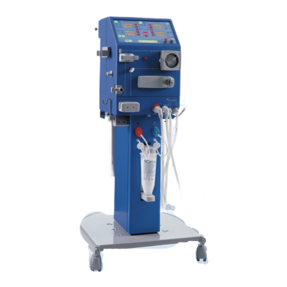
For information about the use and functions of the parameters in level 4, see Ace tate AK 95 Operators Manual, HCEN 9542 or AK 95 S Operators Manual, HCEN 9794. Figure 1. AK 95 S. AK 95 / AK 95 S Service Manual HCEN 9134 Rev. 10.2005... -
Page 25: Fluid Part
Technical Description Fluid Part Flow Diagram Figure 2. AK 95 S Flow Diagram, Bicarbonate/BiCart Valves BYVA Bypass valve INVA Inlet valve TAVA Taration (UF) valve DRVA Degass restrictor valve EVVA Evacuation valve RIVA Rinse valve AIVA Air inlet valve ZEVA... - Page 26 Technical Description AK 95 / AK 95 S Service Manual HCEN 9134 Rev. 10.2005...
- Page 27 Technical Description AK 95 / AK 95 S Service Manual HCEN 9134 Rev. 10.2005...
-
Page 28: Treatment
+130 mmHg. Normaly during treatment INVA is open. The main function of the temperature transduc- ers in the AK 95 S is to measure the dialysis fluid temperature and control the heat regula- tion. The regulating temperature transducer, , is located after the heater. - Page 29 Blood leak detector Expansion chamber Degassing chamber Deairating chamber Variable flow unit (Stepper motor) Line clamp unit Clamp house Dialyzer connection Figure 3. AK 95 S - Fluid part AK 95 / AK 95 S Service Manual HCEN 9134 Rev. 10.2005...
- Page 30 The acid/ MM 95 B, Ac Cart Mixing Chamber Mixing Chamber Feeding Pumps Cond. Cond.Cell "B" Cell "A" FLVA pH-SENSOR Figure 4. MM 95 - Flow diagram AK 95 / AK 95 S Service Manual HCEN 9134 Rev. 10.2005...
- Page 31 Technical Description Feeding Pump Mixing Chambers B Heat Exchanger FLVA Conductivity Cell Figure 5. MM 95 2:10 AK 95 / AK 95 S Service Manual HCEN 9134 Rev. 10.2005...
-
Page 32: Fluid Part, Continue
HPG transducer is above or equal to +550 mmHg calculation since it varies with temperature, (presetable). approximately +1,8 % per °C. 2:11 AK 95 / AK 95 S Service Manual HCEN 9134 Rev. 10.2005... - Page 33 During calibration of the UF measuring unit, the taration valve is closed. TAVA is also closed when the protective system demands a minimum of UF. 2:12 AK 95 / AK 95 S Service Manual HCEN 9134 Rev. 10.2005...
-
Page 34: Disinfection And Rinse
230 V 110 V 100 V will be an attention. With UFD installed When the filling phase is finished the AK 95 S Heat will give an attention that requests you to place Heat Citric acid 20% 52 the B-tube back in the monitor. When this is... -
Page 35: Component Description
(approx.. +130 mmHg). which detects when the tubes are disconnected from the safety coupling. The AK 95 S is also equipped with a pair of Conductivity measuring unit mechanical switches that sense if the dia connec- The unit includes the following components: tors are attached to the bypass block. -
Page 36: Blood Leak Detector
Technical Description CPU board Blood leak detector AK 95 S is equipped with one Control CPU board The blood leak detector includes the following and one Protective CPU board. components: The CPU boards comprises among other things • Housing with cover. -
Page 37: Rear Printed Circuit Boards
Technical Description Rear printed circuit boards Figure 8 . AK 95 S CPU-boards and Driver boards. 2:16 AK 95 / AK 95 S Service Manual HCEN 9134 Rev. 10.2005... -
Page 38: Blood Part
Dialyzer Patient Venous blood line Venous drip chamber Priming Air detector detector Venous line clamp Venous pressure transducer Figure 9. AK 95 S - Blood Flow Diagram. 2:17 AK 95 / AK 95 S Service Manual HCEN 9134 Rev. 10.2005... -
Page 39: Treatment
If the event of an alarm, the blood flow is stopped. If the venous pressure is too high, the cause may • An obstruction after the venous drip chamber. • A change in the patients position. 2:18 AK 95 / AK 95 S Service Manual HCEN 9134 Rev. 10.2005... -
Page 40: Component Description
Technical Description Component Description Figure 10. AK 95 S Blood part - Outside components 1. Operators panel 2. Air detector 3. Venous pressure transducer 4. Arterial pressure transducer 5. Blood pump unit 6. Heparin pump unit 7. Expansion chamber holder... - Page 41 Technical Description Figure 11 . AK 95 S Blood part - Inside components 1. Operators panel 2. Air detector 3. Venous pressure transducer 4. Arterial pressure transducer 5. Blood pump unit 6. Heparin pump unit 7. Expansion chamber holder 8. BM I/O Board 9.
-
Page 42: Priming Detector
• Housing with covers (mounted on the front Arterial pressure transducer plate). AK 95 S can be equipped with a second pressure • 2 solenoids (as one unit). transducer, named Arterial Pressure Trans- •... -
Page 43: Operators Panel
1 numerical display (LED). • 2 knobs. The panel interfaces to the protective driver- board, via 3 board connectors and 3 flat cables. Figure 12. Operators panel 2:22 AK 95 / AK 95 S Service Manual HCEN 9134 Rev. 10.2005... -
Page 44: Bpm
The module includes con- the device to determine if it works or not. trol and protective systems. The device has to be sent to Gambro for repair The control system measures the pressure and incase of malfunction. pulse wave to calculate the systolic, diastolic, mean blood pressure and pulse rate. -
Page 45: Power Supply
Power supply to heater relay board Control CPU board External Fuses: 12 AH T12AH 250AC HALT BACH BACO Contact Fan Intake Mains Switch Figure 13. AK 95 S, AC/DC-unit 2:24 AK 95 / AK 95 S Service Manual HCEN 9134 Rev. 10.2005... -
Page 46: Block Diagram Description
DC supplies to the the heating element. monitor. In a mains power failure situation, the AK 95 S •Two +5 volt supplies, one for the control system gives an intermittent buzzer alarm and performs and the other for protective digital electronics. - Page 47 Technical Description This page is left intentionally blank. 2:26 AK 95 / AK 95 S Service Manual HCEN 9134 Rev. 10.2005...
-
Page 48: Technical Data
Standards ..........3:16 H CEN9369 Revision.10.2005 AK 95 S Service m anual - Technical data and spec ifi cations Program version 12.xx... - Page 49 Heparinization stops before end of treatment 0.00 to 9.59 h Counter pressure: Maximum 400 mmHg Accumulated heparin 0 to 999.9 ml volume: HCEN9369 Revision.10.2005 AK 95 S Service m anual - Technical data and spec ifi cations Program version 12.xx...
- Page 50 High alarm limit, can be 40 - 200 bpm (150 bpm) preset (Default) Meets ANSI/AAMI SP-10 (1992). Mean error ±5 mmHg. Standard deviation 8 mmHg H CEN9369 Revision.10.2005 AK 95 S Service m anual - Technical data and spec ifi cations Program version 12.xx...
- Page 51 - , 20 to 40 mmol/l, (±6 mmol/l) Measuring range: 13 to 16 mS/cm Alarm limits: ±5% of the calculated conductivity set value HCEN9369 Revision.10.2005 AK 95 S Service m anual - Technical data and spec ifi cations Program version 12.xx...
- Page 52 Maximum 20 min, not intended for when not in use overnight disinfection! Total time 30 minutes (with UFD-kit 48 minutes) including 10 min. contact time H CEN9369 Revision.10.2005 AK 95 S Service m anual - Technical data and spec ifi cations Program version 12.xx...
- Page 53 Heat Citric acid 20 % H eat C leanCart Without UFD Heat Heat Citric acid 20 % H eat C leanCart HCEN9369 Revision.10.2005 AK 95 S Service m anual - Technical data and spec ifi cations Program version 12.xx...
- Page 54 It is possible to use water with higher conductivity if it consists mainly of sodium salts. This may however affect the accuracy of the fluid composition. H CEN9369 Revision.10.2005 AK 95 S Service m anual - Technical data and spec ifi cations Program version 12.xx...
- Page 55 10 µA (100 V) 10 µA (110 V) 10 µA current: (230 V) Note: All leakage currents specified are without external equipment connected to the AK 95 S. HCEN9369 Revision.10.2005 AK 95 S Service m anual - Technical data and spec ifi cations Program version 12.xx...
- Page 56 Low level max output -5.0 V voltage: Max output current: ±5 mA RS-422/Current loop: Typ current: 20 mA Max current: 50 mA H CEN9369 Revision.10.2005 AK 95 S Service m anual - Technical data and spec ifi cations Program version 12.xx...
- Page 57 Battery back-up Battery back-up of power 24 volt, 6,5 Ah supply Running time >30 minutes Fuse T 15 A HCEN9369 Revision.10.2005 AK 95 S Service m anual - Technical data and spec ifi cations 3:10 Program version 12.xx...
- Page 58 Supervision of the stop time of the blood pump Alarm: The attention “BLOOD PUMP STOP TIME EXPIRED, Start Blood pump”. H CEN9369 Revision.10.2005 AK 95 S Service m anual - Technical data and spec ifi cations 3:11 Program version 12.xx...
- Page 59 Measuring range: 1 - 9.9 pH, measured in the dialysis fluid before dialyzer. Accuracy: ±0.2 pH Alarm limits: 5.0 to 9.0 pH HCEN9369 Revision.10.2005 AK 95 S Service m anual - Technical data and specificat ions 3:12 Program version 12.xx...
- Page 60 Approx. 1270 mm (without infusion stand). Weight: Approx. 62-78 kg (depending on options). Infusion stand Maximum total load: 2 kg References Assembly Drawing K23000 H CEN9369 Revision.10.2005 AK 95 S Service m anual - Technical data and spec ifi cations 3:13 Program version 12.xx...
- Page 61 Metals Stainless steel SS2343 Stainless steel SS2353 Stainless steel SS2562 Titanium Platinum Others Carbon Ceramic, Steatite 221 Ceramic, Aluminium oxide Glass HCEN9369 Revision.10.2005 AK 95 S Service m anual - Technical data and spec ifi cations 3:14 Program version 12.xx...
- Page 62 Ambient Temperature range -20 to +70 °C Relative Humidity range 10 to 96% RH Air Pressure range ( atm. 500 to 1060 hPa Pressure ) H CEN9369 Revision.10.2005 AK 95 S Service m anual - Technical data and spec ifi cations 3:15 Program version 12.xx...
- Page 63 EN 1060-1 Non-invasive sphygmomanometers Part 1: General requirements EN 1060-3 Non-invasive sphygmomanometers Part 3: Supplementary requirements for electromechanical blood pressure measuring systems HCEN9369 Revision.10.2005 AK 95 S Service m anual - Technical data and spec ifi cations 3:16 Program version 12.xx...
- Page 64 Technical Data Chapter 3 Technical data and specifications for AK 95 AK 95 HCEN9135 Rev. 10.2005...
- Page 65 Technical Data Machine specification AK 95, K18022 Blood flow control Double needle Flow rate: 0 and 20 - 500 ml/min (-150 mmHg prepump pressure, pump segment diameter 7.9 mm) Flow accuracy: ±10 ml/min or ±10 %, whichever is largest Accumulated blood volume: 0 - 999 litres Volume accuracy: ±10 %...
- Page 66 Technical Data Air detection Detection method: Ultrasonic detector placed at the venous drip chamber. The detector has a two channel structure and the function of the detector is tested at the function test made by the microcomputers. Drip chamber size: Diameter 22 mm Sensitivity: Bubbles larger than 1 µl will be trapped by the drip chamber.
- Page 67 Technical Data Safety guard switch (SAGS): Increasing: -59 mmHg, ±7 mmHg Decreasing: -74 mmHg, ±7 mmHg Profiling UF-rate 0.0 to 4 l/h , Acetate mode 130 to 160 mmol/l , Bicarbonate mode 130 to 160 mmol/l , Bicarbonate mode 20 to 40 mmol/l Dialysis fluid preparation Pressure regulators: After pressure regulator...
- Page 68 Technical Data Bicarbonate: , 130 to 160 mmol/l, (±6 mmol/l) - , 20 to 40 mmol/l, (±6 mmol/l) Measuring range: 12 to 16 mS/cm Alarm limits: To 5 % of the calculated conductivity set value pH-meter: 1 – 9.9 pH, measured in the dialysis fluid before dialyzer. ±0.2 pH Accuracy: Alarm limits:...
- Page 69 Technical Data Hypochlorite Program (presetable) Concentration of disinfectant 10 % available chlorine Concentration in machine 0.5 %; i.e. diluted 1 + 19 (1:20) Volume Approx. 145 ml (with UFD-kit approx. 153 ml) Contact time between treatments 10 minutes Contact time overnight or when not in Maximum 20 min, not intended for overnight disinfection! Total time...
- Page 70 Technical Data Auto Heat disinfection: One of two alternatives for auto heat disinfection can be selected. Total Time [min] AK 95 Disinfection 110 V 100 V 230 V programs Heat With UFD installed Heat CleanCart Heat Without UFD Heat CleanCart Temperature: +93°C (measured after heating rod) ≥80°C (measured in the outlet before the heat exchanger )
- Page 71 Technical Data Mains plug: For 100/110V, Hospital grade, earth plug, type IEC 83 A5- For 230V, Dual earth system plug, type IEC 83 C4 100 µA (100V) Maximum earth leakage 150 µA (110V) current: 205 µA (230V, 50 Hz ) 400 µA (230V, 60 Hz ) 9 µA (100V) Maximum patient leakage...
- Page 72 Technical Data Dimensions and weight Width: Machine 350 mm, stand 625 mm. Depth: Machine 420 mm, stand 680 mm. Height: 1270 mm. Weight: 62 kg Infusion stand Maximum total load: 2 kg Materials in contact with dialysate, concentrates and water Polymers Silicon rubber Santroprene...
- Page 73 Technical Data Environmental data – transportation and storage -20 to +70 °C. Ambient temperature: Relative humidity: 10 – 96 % RH Air pressure: 500 to 1060 hPa If transportation or storage time is more than 15 weeks, the environmental data relating to the operation has to be followed.
- Page 74 UF diagnostics ........4:24 Valves diagnostics ........ 4:24 Logging mode ..........4:25 Logging mode flow diagram ....4:26 Error buffers in Logging mode .... 4:27 Arrays ........... 4:28 AK 95 / AK 95 S Service Manual HCEN 9136 Rev. 10.2005...
- Page 75 Time (Remaining treatment time). - Heparin, Priming, Auto Priming (Priming functions) and Rinseback. - Air detect, Attention, Technical alarm, pH, and Blood leak. - Profiling and BPM. AK 95 / AK 95 S Service Manual HCEN 9136 Rev. 10.2005...
- Page 76 4. Stand-by group active mode is indicated by a lit button. For These buttons can be used for direct control and draining of the AK 95 S, press the Rinse/Drain stand-by of certain functions. button twice. Is used to stop and start the blood pump.
- Page 77 Treatment Treatment, fluid bypass, Isolated UF Green Yellow Green Green Green Green Standby, fluid OK/NOT OK Treatment, fluid NOT OK Yellow Yellow Green/Orange Green/Orange Orange Orange Bypass AK 95 / AK 95 S Service Manual HCEN 9136 Rev. 10.2005...
- Page 78 Blood flow, Venous pressure, TMP, and PROM-configurations. This will prevent the UF volume, when “Select” is pressed: possibility of mixing PROMS from different program versions when installing/updating the AK 95 S. If the configuration is invalid, an error Bl:ml/min V :mmH TMP:mmH UFV:l 0.00 code will be issued.
- Page 79 Service Technicians Guide Technical error handling For more information about the error message refer to the Error Code List for AK 95 S, HCEN 9091. Note! It is important that the program version on the Error Code List corresponds with the AK 95 S PROM.
- Page 80 When desired mode is blinking, confirm with the button. START • To store values or modes, press STOP • To step backwards and finally exit from the menu, press AK 95 / AK 95 S Service Manual HCEN 9136 Rev. 10.2005...
- Page 81 Service Technicians Guide Preset mode In the Preset mode the set up of AK 95 S is confirmed. Following choices are set in preset mode: • Start up values • Configuration • Set values and limits • Override times • Auto priming parameters •...
- Page 82 Select Ext with the SET knob and press SELECT key. SELECT key and following display shows up: The AK 95 S Presets are based on the concept of groups. The main groups are: SELECT EXTERNAL PRESET TYPE • 0 Start up...
- Page 83 When ready the machine returns to the first display in Manual preset mode. Note! When selecting Default preset, AK 95 will perform a Chem Rinse at the next start up. 4:10 AK 95 / AK 95 S Service Manual HCEN 9136 Rev. 10.2005...
- Page 84 The time when the venous clamp is open. In order to expell any air bubbles in the venous line. 13 Auto priming FM active Avail / Not Avail 4:11 AK 95 / AK 95 S Service Manual HCEN 9136 Rev. 10.2005...
- Page 85 Time build time drop time Venous Level line fill adjust- ment Flush 2 Pressure test Flush 1 Priming Fill Preset Time parameter 3,4,5 6,7,8 6,10 6,11 6,12 4:12 AK 95 / AK 95 S Service Manual HCEN 9136 Rev. 10.2005...
- Page 86 MAINTENANCE SELECTION Preset Service Example Following example will show how to preset the Select Preset and following text is displayed: AK 95 S for Gambro BiCart together with A- concentrate 201. INITIALIZING PRESET MODE Bicarbonate concentrates SELECT PRESET TYPE Manual Ext Default 1.
- Page 87 COONa NaCl NaCl MgCl MgCl CaCl O with MgCl CaCl O with CaCl NaHCO NaHCO NaCl NaCl COONa COONa O with CH COONa BiCart BiCart BiCart BiCart 4:14 AK 95 / AK 95 S Service Manual HCEN 9136 Rev. 10.2005...
- Page 88 MAINTENANCE SUPPORT SELECTION Logging Service/Preset Select Service/Preset, set the service code and HOLD key, to step backward. enter the Service mode. Following displayshows up: MAINTENANCE SELECTION Preset Service 4:15 AK 95 / AK 95 S Service Manual HCEN 9136 Rev. 10.2005...
- Page 89 (pumps stopped) in External mode. •In Internal AK 95 S maintains a flow. SELECT AD-CONVERTER CPU C CPU P CPU W MM 95 See AD system calibration. 4:16 AK 95 / AK 95 S Service Manual HCEN 9136 Rev. 10.2005...
- Page 90 CONDUCTIVITY A TRANSDUCER CONDUCTIVITY P TRANSDUCER CONDUCTIVITY B TRANSDUCER To step through the Pressing the Select knob Selection diagram (a loop), opens the calibration display. use the SET knob. 4:17 AK 95 / AK 95 S Service Manual HCEN 9136 Rev. 10.2005...
- Page 91 Stand-alone Erasing Chemical disinfection indication REMOVE DISINF/DECALC ATTENTIONS KEEP RINSE/DRN pressed and wait Chemical disinfection indication is OFF! Removing DISINF/DECALC ATTENTIONS Disinfection and Decalcification attentions are removed 4:18 AK 95 / AK 95 S Service Manual HCEN 9136 Rev. 10.2005...
- Page 92 Press SELECT to confirm. I2C EEPROM SCAN COMPLETED DIAGNOSTIC ERROR BUFFER ERASED Name of the transducer: XXXXX EEPROM ADDRESS ERROR Update Escape XXXXX EEPROM NOT INITIALIZED Init Escape 4:19 AK 95 / AK 95 S Service Manual HCEN 9136 Rev. 10.2005...
- Page 93 Press SELECT to view lamps PUMP DIAGNOSTIC MENU Any lamp not lit is defect HEPARIN PUMP DIAGNOSTIC ART FREQ Counters 00000 00000 COUNTERS SETFREQ EST-ACC ACC 00000 00000 00000 4:20 AK 95 / AK 95 S Service Manual HCEN 9136 Rev. 10.2005...
- Page 94 Service Technicians Guide FM diagnostics DIAGNOSTICS FM MENU Var flow Pumps UF Valves See “Variable flow-diagnostics” “Valves-diagnostics” “UF-diagnostics” PUMP DIAGNOSTICS Press direct keys to ctrl FM See “Pump diagnostics” 4:21 AK 95 / AK 95 S Service Manual HCEN 9136 Rev. 10.2005...
- Page 95 Pump diagnostics The machine uses concentrate pump A and conductivity cell A to regulate the conductivity. In Pump Diagnostics the AK 95 S enters “nor- When the conductivity is stabilised (for 10 sec- mal” treatment mode, starts the fluid part and onds) inside ±5 % of the set value and the tem-...
- Page 96 This mode can be used to check how many steps the stepping motor needs to move to obtain a flow of 500 ml/min. Start the AK 95 S, enter the Service menu and select Calibrations. Place A-pickup tube in the concentrate container.
- Page 97 EVACUATION VALVE EVVA BYPASS VALVE CPU C BYVA BYPASS VALVE CPU P BYVA Note! Be careful when open the AIVA to avoid Fluid leakage into the monitor. 4:24 AK 95 / AK 95 S Service Manual HCEN 9136 Rev. 10.2005...
- Page 98 The actual information is shown on the informa- tion display, which is divided into three fields (0 - 2). It is possible to choose any AK 95 S parameter for any of the three fields. See Logging mode flow diagram.
- Page 99 "Arrays", page 4:28 Select array index (000 - 999). Select the array to be displayed (see "Arrays", page 4:27) In which field the logged parameter will appear. 4:26 AK 95 / AK 95 S Service Manual HCEN 9136 Rev. 10.2005...
- Page 100 C COFB 088 043 20 Oct 05 16:37 For more information about the error message refer to page 4:6 and the Error Code List for AK 95 S, HCEN 9091. 4:27 AK 95 / AK 95 S Service Manual HCEN 9136 Rev. 10.2005...
- Page 101 Summary: 1. Set field 2. Set array 3. Set index 4. Push twice to step back 5. Push “display” to see the logged parameters. 4:28 AK 95 / AK 95 S Service Manual HCEN 9136 Rev. 10.2005...
-
Page 102: Maintenance Manual
Maintenance Manual AK 95 / AK 95 S October 2006 G A M B R O... - Page 104 Preventive Maintenance: B- and C-kit ... 5:17 Parts .............. 5:17 How to exchange the parts included in the B- and C-kit ......... 5:18 Actions to carry out after the parts have been exchanged ..........5:20 AK 95 / AK 95 S HCEN12189 Rev. 10. 2006...
-
Page 105: Calibrations
Any warranties made by Gambro with respect to During repair of any of the parts in the flow the AK 95 / AK 95 S are void if the equipment is path, special care should be taken and a good not used in accordance with the instructions hygiene should be kept. - Page 106 Gambro K22151001 *BPM Cuff Gambro 100900141 *pH buffers ± 0.07 pH units pH 7 – 100810001 pH 9 – 100810002 Magnet for blood pump cover Gambro K19049001 * If installed AK 95 / AK 95 S HCEN12189 Rev. 10. 2006...
- Page 107 Base-kit Preventive Maintenance: Base-kit Parts The Base-kit (K40182001) includes all parts necessary to fulfill the mandatory preventive maintenance procedures for AK 95 / AK 95 S. l i f l i f l i f r t l t l i...
- Page 108 Then perform a heat disinfection program in combination with CleanCart A or a Chemical disinfection program with sodium hypochlorite. Refer to the AK 95 or AK 95 S Operator’s Manual. Change o-rings, 100319061, on the A and B-concentrate connectors (male).
- Page 109 Maintenance Manual Change the O-rings, 100319029, and Change the level detector, K40136001, in square-ring, K14920001 in the ultrafilter the deairating chamber. Use the attached o-ring, 100319054. holder. (Only for AK 95 S with UFD-kit) 100319029 K40136001 K14920001 100319054 100319029 Change the sample port for 6 mm tube, Change both upper, 100319008, and lower K20219002.
- Page 110 Change both upper, 100319008, and lower o-rings, 100319050, in the mixing chambers. 100319008 100319050 Mark month and year for the next scheduled preventive maintenance. Attach the label to the rear cover of the machine. AK 95 / AK 95 S HCEN12189 Rev. 10. 2006...
- Page 111 Attach BPM cuff, 100900141, tight to the for AK-machines. test equipment, K22151001. Check the protective earth resistance: Start the AK 95 S with the main switch and the ON/OFF button. Measure between TP 5 (Z0VL) on the Enter Service mode.
- Page 112 AK 95 S. In this case replace the cuff and cuff hose by a tube, which is closed. Note! Pressures shall be applied very carefully so that no overpressures occur.
- Page 113 Maintenance Manual Base-kit Priming detector calibration Use following formula to calculate which Start the AK 95 S, enter the Service menu gage pin to use: and select Calibrations. 2 * wall thickness * 0,7 (mm) Select Transducer, External and PRIMING DETECTOR from the selection diagram.
- Page 114 Calibrate if necessary (see chapter Transducer. calibration for details). Tolerance: ± 5 mmHg. Calibrate if necessary (see chapter Drain the AK 95 S and replace the blood calibration for details). leak calibration cover. Enter Diagnose/BM/Pumps and check that Attach pressure reference instrument the blood pump stops when the cover is before the heater.
- Page 115 Check the DC leakage between TP 5 Turn on the power supply main switch (Z0VL) on the Control CPU board and the again and start the AK 95 S. suction pump head. Measure in DC Voltage, should be < 1 V.
- Page 116 Simulate blood in the priming detector with a Perform heat/chemical disinfection. piece of paper. Make sure (again) that the measuring glass is filled to 1.00 liter. Press the UF START/STOP button. 5:13 AK 95 / AK 95 S HCEN12189 Rev. 10. 2006...
- Page 117 Preventive Maintenance: Supplementary A-kit Parts The A-kit is designed to be used as a complemen- tary addition to the Base-kit for the preventive maintenance procedures of AK 95 / AK 95 S. The A-kit (K40179001) includes following exterior parts: e t l...
- Page 118 K 40183001 (blue) and K 40184001 (red). - Pick-up tube, A (white) 100850007 - Pick-up tube, B (blue) 100850008 - Pick-up tube, (yellow) 100850021 A c e ta te K40183001 K40184001 5:15 AK 95 / AK 95 S HCEN12189 Rev. 10. 2006...
- Page 119 Check the range between the blood First perform a heat disinfection program. pump rollers and the path according to Refer to the AK 95 or AK 95 S Operator’s the picture below. Manual. After the heat disinfection; re-tighten the nuts of the dialyser connector set to the machine.
- Page 120 ) . h , t i t r a o l ( , t i 5:17 AK 95 / AK 95 S HCEN12189 Rev. 10. 2006...
- Page 121 B-kit only! Change all the Santoprene tubes in the Change valve membranes, K08056C, fluid monitor. for following valves: AIVA, ZEVA, DIVA, BYVA, TAVA, EVVA and FLVA. See instructions on page 5:20. 5:18 AK 95 / AK 95 S HCEN12189 Rev.10. 2006...
- Page 122 Assemble according to machine configuration. Change the o-rings, 100335001, in the parker couplings to and from INPS. 100335001 100335001 Change the o-rings, 100335001, in the parker couplings from the heat exchanger. 5:19 AK 95 / AK 95 S HCEN12189 Rev. 10. 2006...
- Page 123 Valve mounting tool K15391C A special service tool for mounting of the valve membrane correctly in the valve housing is available. 5:20 AK 95 / AK 95 S HCEN12189 Rev.10. 2006...
- Page 124 Maintenance Manual Actions to carry out after the parts have been exchanged First perform a heat disinfection program. Refer to the AK 95 or AK 95 S Operator’s Manual. Let the machine pass FCH. 5:21 AK 95 / AK 95 S HCEN12189 Rev.
- Page 125 Maintenance Manual This page is intentionally left blank 5:22 AK 95 / AK 95 S HCEN12189 Rev.10. 2006...
- Page 127 Gambro Lundia AB, Monitor Division Box 10101 SE-220 10 Lund Sweden Tel:+46 46 16 90 00 Fax:+46 46 16 96 96 www.gambro.com...
- Page 128 HPG Pressure Transducer Calibr ..6:15 Variable flow calibration ...... 6:16 UF Calibration ........6:17 General ..........6:17 Complete ..........6:18 Intern ............ 6:19 Verify ............ 6:20 BPM test ..........6:21 AK 95 / AK 95 S Service Manual HCEN 9138 Rev. 10.2005...
-
Page 129: Technical Facilities
A piece of blood tube used at the hospital. Blood leak detector Calibration cover K40169001 Pressure Reference instrument 300333001 Calibration kit K13983002 Special tool For silicone tube connectors K12755001 Calibration kit AK 95 / AK 95 S Service Manual HCEN 9138 Rev. 10.2005... - Page 130 Calibrations AD Converters Set the “AD REF VOLTAGE” on the Start the AK 95 S, enter the Service menu display to the value shown on the voltme- and select Calibrations. ter and press Choose AD-converter. When selecting “AD-Converter” from the display...
-
Page 131: Calibration Of Linear Transducers
Calibrations Transducers Calibration of linear transducers • Select Internal and the AK 95 S main- Start the AK 95 S, enter the Service tains a flow during the calibration. menu and select Calibrations. Independently wich flow support is chosen Choose Transducers the Selection diagram turns up. -
Page 132: Venous Pressure Transducer Calibr
+500 Connect the Gambro reference instrument (together with a calibration tube set) to Set the “REF SET” value on the AK 95 S the venous pressure transducer on the to the reading on the reference instrument front of the AK 95 S, see fig. below. -
Page 133: Arterial Pressure Transducer Calibr
+500 the arterial pressure transducer on the front of the AK 95 S, see fig. below. Set the “REF SET” value on the AK 95 S to the reading on the reference instrument Zeroset the reference instrument, wait for and press stable reading. -
Page 134: Priming Detector Calibration
Priming Detector calibration Occlusion adjustment, blood pump/ infusion pump Start the AK 95 S, enter the Service menu and select Calibrations. Check surface on the roller at the pump rotor, if it is damaged exchange the unit. The roller unit... -
Page 135: Blood Leak Detector Calibration
Calibrations Blood Leak Detector calibration Make sure there is no fluid in the AK 95 S If a calibration error occurs: Monitor. If fluid in the monitor, press Rinse/Drain. • Check the position of the calibration filter and repeat from point 1. -
Page 136: Conductivity Transducer Calibration
STOP Set the temperature to 37,5°C (by pressing into the EEPROM. TEMP key) and let the AK 95 S and the refer- ence instrument stabilize for at least 30 min- All the transducers A, B and P are all calibrated utes. - Page 137 Close clamp A. Apply a pressure of approx. -500 mmHg, shown on the reference instrument. Close clamp B. Set the “REF SET” value on the AK 95 S to the reading on the reference instrument and press twice.
- Page 138 Calibrations Degassing Pressure Transducer Calibration Disconnect tube no. 50 at the Expansion Set the “REF SET” value on the AK 95 S to chamber. Connect the Gambro reference the reading on the reference instrument instrument to tube no. 50 via the calibra- and press tion tube set.
-
Page 139: Ph Transducer Calibration
Remove the pH sensor from the pH sensor housing by loosening the nut holding the pH sensor and rinse the sensor in distilled water. Check that the “REF SET” on the AK 95 S displays pH 7. 6:12 AK 95 / AK 95 S Service Manual... - Page 140 STOP water. into the EEPROM. Check that the “REF SET” on the AK 95 S Remount the pH-sensor into the pH sensor displays pH 7. housing. Put the pH sensor in a cup with pH 7 If an error message is shown after this buffer solution (ordering no.
- Page 141 PR 1 switch °C AIVA Suction Heat Pump exchanger Drain Outlet Restrictor AK 95 S Inlet/Outlet Flow Diagram. The complete Flow Diagram is showed at page 2:5. 6:14 AK 95 / AK 95 S Service Manual HCEN 9138 Rev. 10.2005...
-
Page 142: Hpg Pressure Transducer Calibr
Close clamp A. Apply a pressure of approx. -500 mmHg, shown on the reference instrument. Close clamp B. Set the “REF SET” value on the AK 95 S to the reading on the reference instrument and press twice. -
Page 143: Variable Flow Calibration
This value will then be used during functional check and when entering service mode as the flow always should be 500 ml/min in functional check and service mode. Start the AK 95 S, enter the Service menu and select Calibrations. Place A-pickup tube in the concentrate container. -
Page 144: Uf Calibration
500 ml/min. It requires that the the UF-measuring unit. external UF calibration equipment is connected to the AK 95 S, see fig.below. The equipment The UF-measuring unit consists of two flow contains a reference volume, a flow directing measurement channels called channel 1 (CH 1) valve (UFVA) and a UF- calibration box. - Page 145 First the display for UF Volume for 3 seconds: (but nothing will get destroyed) if the cable is reversed. UF VOL REF VOL VOL DIFF 2. Start the AK 95 S with the main switch and 1006.5 1007.3 -0.28 % the ON/OFF button.
- Page 146 Calibrations Intern When the internal UF calibration is ready: 1. Start the AK 95 S with the main switch and After the calibration , A K 9 5 S d i s p l a y s : the ON/OFF button.
- Page 147 1006.5 1007.3 -0.28 % will get destroyed) if the cable is reversed. 2. Start the AK 95 S with the main switch and Then the display for Isolated UF Volume for 3 the ON/OFF button. seconds: 3. Place B-pickup tube in the acetate-concentrate ISO VOL REF VOL VOL DIFF container.
-
Page 148: Bpm Test
250 ± 3 mmHg 1. Attach cuff no. 3 tight to the BPM test equip ment, according to the illustrations below: 2. Start the AK 95 S with the main switch and the ON/OFF button. 3. Enter Service mode. 4. Enter Diagnostics mode. - Page 149 3 and cuff hose no. 1 to be connected to the check the actual pressure value for the BPM AK 95 S. Cuff no. 3 to be wrapped tight to the pressure on the AK 95 S display. BPM test equipment K2 2151 001.
- Page 150 Possible causes are pressure transducer or electronic circuits mal- function. The BPM module must then be re- placed and sent to Gambro for repair. 6:23 AK 95 / AK 95 S Service Manual HCEN 9138 Rev. 10.2005...
- Page 151 Calibrations This page is intentionally left blank 6:24 AK 95 / AK 95 S Service Manual HCEN 9138 Rev. 10.2005...
-
Page 152: Spare Parts List
Spare Parts List AK 95 & AK 95 S October 2005... - Page 154 Spare Part List Item Spare Part List Denomination Order no. Remarks 10.2005 Contents : Front panel outside ........ 7-1 Front panel inside ........7-2 Operators panel ........7-3 Blood pump ..........7-4 Blood pump, Motor unit ......7-5 Heparin pump ........7-6 Bottom box ..........
-
Page 155: Front Panel Outside
7-1 Front panel outside 5,24 HCEN9094 Rev. 10.2005... - Page 156 Spare Part List Item Denomination Order no. Remarks Front panel K21747001 AK 95: K21747002 O-ring 100318054 100320065 Cabling, reciving K21166001 O-ring 100318064 PT-screw 100366314 Level detector door K15114002 Shaft K17529001 Spring 100346026 Roller K12994001 Lundia 11 arm K15541B Multi holder K20397003 Lundia Multi holder N01870003...
-
Page 157: Front Panel Inside
7-2 Front panel inside venous pressure sensor arterial pressure sensor HCEN9094 Rev. 10.2005... - Page 158 Spare Part List Item Denomination Order no. Remarks Protective cover K19412001 BM I/0 board K40111002 O-ring 100318064 Luer nut K11830003 Luer cone K18760001 Screw 100368410 Luer house K16001003 Screw 100378406 Arterial pressure line K15168001 to P612 BM I/O board Pressure transducer board K16980001 Luer nut K11830002...
-
Page 159: Operators Panel
7-3 Operator's panel HCEN9094 Rev. 10.2005... - Page 160 Finnish (AK 95 S) Overlay K23812001 Danish (AK 95 S) Overlay K23813001 Slovak (AK 95 S) Overlay K23814001 NL / BE (AK 95 S) Overlay K23815001 Turkish (AK 95 S) Overlay K23816001 Polish (AK 95 S) Overlay K23817001 Japanese (AK 95 S)
-
Page 161: Blood Pump
7-4 Blood pump HCEN9094 Rev. 10.2005... - Page 162 Spare Part List Item Denomination Order no. Remarks Bearing unit, CCW rotation K15610001 incl. item 4,6,7 O-ring 100318112 Race with cover K19694A A=arterial B=venous incl. item 5 PT-screw 100368226 Cover K19693A A=arterial B=venous incl. magnet Magnet plate K15662001 Rotor guard bord K15670003 Screw 100379516...
-
Page 163: Blood Pump Motor Unit
7-5 Blood pump Motor unit HCEN9094 Rev. 10.2005... - Page 164 Spare Part List Item Denomination Order no. Remarks Motor bracket K16432001 Motor compl. K40168001 incl. transmission Cablage motor BPA K23945001 to P614 BM I/O board Flexible mounting 100332013 Nut M6 M4 100390400 Edging strip 100312070 Protecting cover K11859001 Screw MCS 3x4 100370304 Clutch half assembly K04898003...
-
Page 165: Heparin Pump
7-6 Heparin pump HCEN9094 Rev. 10.2005... - Page 166 Spare Part List Item Denomination Order no. Remarks Motor complete K11792001 Belt 100329093 Encoder unit complete K16179001 O-ring 100318112 Locking washer 100322011 Screw 100378406 Housing K15765002 Piston Holder K15782002 Heparin pump complete K15761002 incl. 1, 2, 3, 7, 8 HCEN9094 Rev.10 .2005...
-
Page 167: Bottom Box
7-7 Bottom box 27,28 26,41,45 30,31 HCEN9094 Rev. 10.2005... - Page 168 Spare Part List Item Denomination Order no. Remarks Bottom box K19900B AK 95: K19900A Protective cap 100334283 Pressure switch ( SAGS ) K40115004 O-ring 100319044 Safety bypass house K12789001 PT-Screw 100368410 Washer K12957001 Nipple K14028002 100391002 Plug 100334219 Screw 100378410 Washer K17269001 Filter housing...
-
Page 169: Magnetic Clamp Unit
7-8 Magnetic Clamp unit 8,12,16 10,11 17,18 HCEN9094 Rev. 10.2005... - Page 170 Spare Part List Item Denomination Order no. Remarks Screw 100378420 Clamp driver board K11332001 Double magnet K11866A O-ring 100318010 Compression shoe K04403003 Screw 100370416 PT-screw 100367308 PT-screw 100366258 Light guide 1 K14834001 Light guide 2 K14835001 O-ring 100318111 Priming detector board K11335003 Shaft K18042001...
-
Page 171: Blood Leak Det. Suction Pump Unit
7-9 Blood leak det., Suction pump unit HCEN9094 Rev. 10.2005... - Page 172 Spare Part List Item Denomination Order no. Remarks Pump unit K18998001 Screw 100370450 Gasket K13572001 glue Screw 100370430 Nipple K14158001 Cover K16215002 O-ring K16214001 Blood leak detector K15943001 Tube no. 29A K16039001 Flow reducer K05314001 Washer 100392902 Connector straight K10986001 Tube no.
-
Page 173: Uf Measuring Unit
7-10 UF measuring unit HCEN9094 Rev. 10.2005... - Page 174 Spare Part List Item Denomination Order no. Remarks UF measuring unit compl. K40139001 FM I/0 board K40152001 Temp unit K12781A Fluid protection K20249001 Connector angeled K11982001 Tube no. 23 K15268001 Tube no. 12B K12889001 to cond. cell, upper Tube no. 31 K12883001 T- Connector K12961001...
- Page 175 7-11 Bottom plate, Conductivity cell HCEN9094 Rev. 10.2005...
- Page 176 Spare Part List Item Denomination Order no. Remarks PT-screw 100369360 Fluid protection K13271001 Screw 100373408 Clips 100314181 Fan complete K12753A Tube 100312093 to press.regulator Clamp 100334203 Connector straight 100334040 exl. item 9 Washer 100335002 Housing K12789001 INPS Nipple K16260002 O-ring 100319044 Cabling K13030001...
-
Page 177: Bottom Plate, Degassing Pump
7-12 Bottom plate, Degassing pump 29,44,42,18 HCEN9094 Rev. 10.2005... - Page 178 Spare Part List Item Denomination Order no. Remarks Degassing chamber, compl. K12950002 Float complete K15848A Screw 100370405 Tube 100312056 198 mm Tube no. 28 K12886001 O-ring 100319050 Screw 100370408 Connector, angled K12951001 O-ring 100319008 Distans screw 100316102 Tube, silicone 100312032 80mm Deairating chamber, complete K12830003...
- Page 179 7-12 Bottom plate, Degassing pump 29,44,42,18 HCEN9094 Rev. 10.2005...
- Page 180 Spare Part List Item Denomination Order no. Remarks Earth cable K18592001 to dialysis tube guard Level guard K40136001 O-ring 100319029 Motor K40126001 Pump head K19157001 incl. driving magnet,pump head Mounting plate for degassing chamber K20463001 Degassing chamber complete K12950002 Pump repair kit K19143001 Battery 100224006...
-
Page 181: Heater, Flow Guard
7-13 Heater, Flow guard HCEN9094 Rev. 10.2005... - Page 182 Spare Part List Item Denomination Order no. Remarks Screw 100370410 Heater compl. K40114001 100V, 1000W Heater compl. K40114002 115V, 1300W Heater compl. K40114004 230V, 3 x 580W O-ring 100319055 Tube no. 78 K19364001 Connector T K12961001 Temp. transducer compl. K12781A Tube no.
-
Page 183: Center Plate, Valves
7-14 Center plate, Valves HCEN9094 Rev. 10.2005... - Page 184 Spare Part List Item Denomination Order no. Remarks Screw 100378325 Screw 100378330 Valve membrane K08056C 100316082 Valve housing complete K16617A Solenoid valve K15035001 Tube no.15 K15581001 Tube C K16457001 Valve housing complete K15235A Screw 100378304 Tube 100312056 30 mm T-connector K12961001 Connector straight K10986001...
-
Page 185: Center Plate, Tubes
7-15 Center plate, Tubes 22 21 20 HCEN9094 Rev. 10.2005... - Page 186 Spare Part List Item Denomination Order no. Remarks Tube 100312032 Pressure regulator complete 100313252 Nippel K01515002 Tube 100312056 30 mm Connector straight K10986001 Connector angel K12951001 Center plate K16348A Reducer K24016001 T-connector K12961001 Valve housing complete K15235A 9 pcs. Tube K15372001 Chamber complete K16884004...
-
Page 187: Variable Flow Unit
7-16 Variable flow unit to Step driver board 13,14,15 9,10 HCEN9094 Rev. 10.2005... - Page 188 Spare Part List Item Denomination Order no. Remarks Motor holder K15162001 Cable K23957001 to step driver board Flow restrictor K24016001 Screw 100378330 Tube 100312056 30 mm Locking nut 100316082 Locking nut 100316046 Screw 100378430 Screw 100380304 100320079 Motor K13403B Valvehouse Spec. complete K24055001 Spacer K15049001...
-
Page 189: Boards
7-17 Boards HCEN9094 Rev. 10.2005... - Page 190 Spare Part List Item Denomination Order no. Remarks Protective Driver board K17552003 with frame Protective CPU board K17553005 with frame Control CPU board K17554006 with frame Control Driver board K17555004 with frame Quick-acting lock K04813001 PT-screw 100368410 Screw 100370440 Screw 100370425 Fiber washer 100322049...
-
Page 191: Rear Box
7-18 Rear box HCEN9094 Rev. 10.2005... - Page 192 Spare Part List Item Denomination Order no. Remarks Infusion stand,straight K19073B Screw 100388612 Knob 100300048 Cover, rear K18493B AK 95: K18493A Air filter K12966001 Rear cover Infusion stand,angled K19073A Filter holder K16963001 Insert holder, left K12731A Included in item 4 Insert holder, right K12963A Included in item 4...
-
Page 193: Protective Covers
7-19 Protective Covers *The figures do not correspond to their actual sizes. HCEN9094 Rev. 10.2005... - Page 194 Spare Part List Item Denomination Order no. Remarks Protective cover K17187001 operators panel, see 7: 3 Protective cover K19412001 BM I / O board Protective cover K23874001 FM I/O board Protective cover K23857001 Relay board Top tray K19864001 Protective cover K19836001 AC/DC, see 7:19 Protective cover...
-
Page 195: Ac / Dc
7-20 AC / DC T12AH 250AC HALT BACH BACO HCEN9094 Rev. 10.2005... - Page 196 Spare Part List Item Denomination Order no. Remarks AC / DC K40130001 Fuse 12AT 100213113 Filter K23734001 Clamp 100314011 Screw 100370408 100316046 Earth cable K18591001 to bottom plate, rear Locking washer 100322011 Protective cover K19836001 Mains cable K40159001 100-115 V Mains cable 100220212 230 V...
-
Page 197: Mm95 With Stand
7- 21 MM95 with Stand 24,25 HCEN9094 Rev. 10.2005... - Page 198 Spare Part List Item Denomination Order no. Remarks Screw 100370410 Front K19840D AK 95: K19840C Stand K16272B Cover, left K16494D AK 95: K16494C Cover, right K16495004 AK 95: K16495003 Screw 100378406 Locking fluid Screw 100370440 Frame, upper complete K16703D AK 95: K16703C Screw 100388812 Plug...
-
Page 199: Bpm, Battery Backup - (Option), Ph
7- 22 BPM, Battery backup - (Option), pH 14,41 29-40 27,28 16,17 22,23 24,25 HCEN9094 Rev. 10.2005... - Page 200 Spare Part List Item Denomination Order no. Remarks Blood pressure monitor board K40127001 BPM plate K23504A Cabling K23531001 BPM to PCB-BPM Protective cover K23555001 Protective cover K23556001 Blood pressure module K40128002 Flat cable ferrite 100120102 Mounting clips 100120103 Spacer screw 100316315 Screw 100370304...
-
Page 201: Inflow Unit
7-23 Inflow unit 21 27 Left view HCEN9094 Rev. 10.2005... - Page 202 Spare Part List Item Denomination Order no. Remarks Pressure regulator 100313254 Heat exchanger K15876005 110V Heat exchanger K15876006 110V/220V Heat exchanger K15876007 110V Heat exchanger K15876008 110V Holder K20194001 Holder K16276001 Clamp 100334203 Tube armoured 100312093 260 mm Tube armoured 100312093 85 mm Tube armoured...
-
Page 203: Front, Mm95
7-24 Front, MM95 HCEN9094 Rev. 10.2005... - Page 204 Spare Part List Item Denomination Order no. Remarks Front K19840D AK 95: K19840C Concentrate nipple K17990007 Concentrate nipple K17990008 Concentrate intake K17991007 Concentrate intake K17991008 O-ring 100319061 Cabling PTBH AK 95 K18205001 to MM I/O board P703 PT sensor board K18254001 Connector K17725001...
-
Page 205: Mm I/O Board
7-25 MM I / O board HCEN9094 Rev. 10.2005... - Page 206 Spare Part List Item Denomination Order no. Remarks Edgin strip 100312029 MM I/O board K40090002 Spacer 100316222 Spacer 100316223 Screw 100370310 Protective cover K16763001 Screw 100370406 Locking washer 100322010 Locking nut 100316082 Mounting plate K16274001 HCEN9094 Rev.10 .2005...
-
Page 207: Feeding Pumps
7-26 Feeding pumps HCEN9094 Rev. 10.2005... - Page 208 Spare Part List Item Denomination Order no. Remarks Tube, silicone 100312032 190 mm Motor unit K14621001 incl. handle wheel 100390400 Flexible mounting K02691001 Screw 100388612 Screw 100378408 Tube, soft 100312012 Tube, silicone 100312032 100 mm Nipple K01515002 Tube, silicone 100312032 300 mm Tube, silicone 100312032...
-
Page 209: Mixing Chamber, Flushing Valve
7-27 Mixing chamber, Flushing valve HCEN9094 Rev. 10.2005... - Page 210 Spare Part List Item Denomination Order no. Remarks O- ring 100319050 Mounting bracket K13992001 Screw 100370406 Screw 100370410 Nipple K01515002 T- Connector K12961001 Connector, angled K12951001 Tubes, silicone 100312032 100 mm Tube 100312056 245 mm Tube no. 4 K14735001 Valve connector K15937001 Connector K10986002...
-
Page 211: Conductivity Cells
7-28 Conductivity cells Conductivity cell, left Conductivity cell, right HCEN9094 Rev. 10.2005... - Page 212 Spare Part List Item Denomination Order no. Remarks Conductivity cell complete K40102002 Tube no. 48 K16759001 Tube, santoprene 100312141 250 mm Nipple K01515002 Tube no. 10 K15731001 Fluid protection K13271001 Tube K13231004 PT-screw 100369360 Tube 100312056 245 mm Cabling K11291001 T- Connector K12961001 Connector, angled...
-
Page 213: Bicart Holder
7-29 BiCart holder 6,9,10 7,9,10 HCEN9094 Rev. 10.2005... - Page 214 Spare Part List Item Denomination Order no. Remarks Arm, upper K23031002 Arm, lower K21557005 Sealing K17502001 Shaft K17481001 Spring K17503001 Bypass nipple K14908001 BCH bypass valve K14425001 Cabling K14910001 O-ring 100319026 4 pcs. Retaining ring 100330021 Tube, silicone 100312032 190 mm Magnet K19049002 T-connector...
-
Page 215: Ufd (Option)
7-30 UFD (Option) HCEN9094 Rev. 10.2005... - Page 216 Connector, T K12961001 Tube 54 K19876001 Tube 55 K19877001 Tube 56 K19878001 Tube 57 K19879001 Tube 62 K20671001 Tube 63 K20672001 Tube 64 K20673001 Tube 65 K21507001 Cabling valves AK 95 S K16712001 Screw 100370406 Screw 100378530 HCEN9094 Rev.10 .2005...
-
Page 217: Remote Panel (Option)
7-31 Remote panel (Option) 12,7 16,17 19,20,21 HCEN9094 Rev. 10.2005... - Page 218 Spare Part List Item Denomination Order no. Remarks Front panel K40140001 incl. gasket Gasket K12717001 Blind panel K21648002 Holder K21651001 Spacer 100316307 Cable strap 100314312 Washer 100322011 Screw 100374408 Protective cover K23184001 O-ring K23195001 Holder K23046001 Screw 100385408 Rear panel K23191A Washer 100322049...
-
Page 219: Boards And Cablings
7-32 Boards and Cablings 10. Step driver board HCEN9094 Rev. 10.2005... - Page 220 Spare Part List Item Denomination Order no. Remarks 1 Protective Driver Board K17552003 ( with frame ) P200 cabling K18133001 to control Driver board P408 P201 cabling K21166001 to air detector P202 cabling K18169001 to FM I/O board P509 P203 to protection CPU board P100 P204 cabling...
- Page 221 7-32 Boards and Cablings 10. Step driver board HCEN9094 Rev. 10.2005...
- Page 222 Spare Part List Item Denomination Order no. Remarks 6 MM I / O Board K40090002 P700 to pH-electrode P701 cabling K11291001 to conductivity cell A P702 cabling K11291001 to conductivity cell B P703 cabling K18205001 to BiCart holder and pick-up tubes P704 cabling K16727001...
- Page 223 Gambro Lundia AB, Monitor Division Box 10101 SE-220 10 Lund Sweden Tel: +46 46 16 90 00 Fax: +46 46 16 96 96 www.gambro.com...
-
Page 225: Symbol Description
Chapter 9 Symbol Description HCEN9160 Revision 10. 2005 Service Manual - Symbols... - Page 226 List of symbols NOTE All symbols in this list may not be represented on this product. Description Alternating current Protective earth (ground) Warning, consult accompanying documents Off (power, disconnection from the mains) On (power, connection to the mains) Type B, applied part Handle with care This way up Keep dry...
- Page 227 CSA approved for Canada and USA CSA-listed label manufacturer Prohibited behaviour Equipotentiality Separate collection for electrical and electronic equipment HCEN9160 Revision 10.2005 Service Manual - Symbols...
- Page 228 This page is left intentionally blank HCEN9160 Revision 10. 2005 Service Manual - Symbols...
-
Page 229: Replacements
Replacements Replacements Replacement matrix........2 Changeactions ............. 4 FM Flow Diagram ..........5 10:1 AK 95 / AK 95 S HCEN12078 Rev.10.2005... - Page 230 In the matrix, BM stands for Blood Monitor and FM stands for Fluid Monitor. The replacementmatrix is only a guideline for service technicians which actions to perform when a component has been replaced. 10:2 AK 95 / AK 95 S HCEN12078 Rev.10.2005...
- Page 231 Replacements 10:3 AK 95 / AK 95 S HCEN12078 Rev.10.2005...
- Page 232 Calibrate according to calibration instructions in the Service Manual, Calibration Manual. the Service Manual, Calibration Manual. Start the machine and let it perform a Function Check. Heat disinfection Perform a heating according to the Operators Manual. 10:4 AK 95 / AK 95 S HCEN12078 Rev.10.2005...
- Page 233 Replacements FM Flow Diagram 10:5 AK 95 / AK 95 S HCEN12078 Rev.10.2005...
- Page 234 Replacements This page is intentionally left blank 10:6 AK 95 / AK 95 S HCEN12078 Rev.10.2005...
-
Page 235: Electrical Safety Inspections
Electrical Safety Inspections for AK-machines Including following sub-tests: - Visual inspection - PET - Protective earth test - ELT - Earth leakage current test - PLT - Patient leakage current test Electrical Safety Inspections for AK-machines 11:1 HCEN12190 Rev 05.2006... - Page 236 General information To ensure proper operation, a qualified service technician must per- form an Electrical Safety Inspection (ESI) of the AK-machine at reg- ular intervals. The information needed to perform ESI is provided in this manual. Included in the ESI procedures are checks to verify normal machine operation.
- Page 237 Visual inspection The visual inspection is an important part of the electrical safety inspections of the AK-machine. The visual inspection is a procedure to make sure that the medical equipment in use still confirms the specifications and has not suffered from any external damage and/or contamination.
- Page 238 Manufacturer: e.g. Fluke ± 0.5 % Resistance: accuracy PET for AK 95 / AK 95 S Check that the resistance between the grounding clips of the mains plug and the exterior cover of the power supply is < 0.3 Ohm.
- Page 239 PET for AK 200 / AK 200 ULTRA / AK 200 S / AK 200 ULTRA S Check that the resistance between the grounding clips of the mains plug and the power supply (right side, through the vent- holes of the bottom box) is < 0.3 Ohm. Check that the resistance between the grounding clips of the mains plug and the FM bottom plate is <...
- Page 240 ELT / PLT Test equipment Safety tester: According to IEC 60601-1 Suggested Manufacturer: Metron, Rigel, Biotec General conditions for ELT / PLT The AK-monitor shall be connected to both feed water and drain. Connect the AK-monitor to the outlet supply of the safety tester. Use a mains plug adapter for respective mains plug.
- Page 241 Take the highest reading when the machine is running. Check that the highest measured readings don’t exceed the limit values in following table: Limit values for ELT AK 95 S (100V) Max 500 µA Typical < 100 µA AK 95 S (110V) Max 500 µA...
- Page 242 Take the highest DC-reading when the machine is running. Check that the highest measured readings don’t exceed the limit values in following table: Limit values for PLT AK 95 S (100V) Max 100µA Max 10µA Typical <10µA AK 95 S (110V) Max 100µA...
- Page 243 NOTE For treatments with a central venous catheter (CVC), the patient leakage current must be < 10µA Electrical Safety Inspections for AK-machines 11:9 HCEN12190 Rev 05.2006...
- Page 244 This page is intentionally left blank 11:10 Electrical Safety Inspections for AK-machines HCEN12190 Rev 05.2006...
- Page 245 Visual inspection Visual inspection of the AK-machine according to section 2. PET for AK 95, AK 95 S (1) Resistance between the grounding clips of the mains plug and the exterior cover of the power supply is < 0.3 Ohm.
- Page 246 ELT - Earth Leakage Current Test File the highest earth leakage current value when the machine is running according to section 4.3: Earth leakage current value: _______ µA Note! Check that the highest measured readings don’t exceed the limit values described in section 4:3 PLT - Patient Earth Leakage Current Test File both the highest AC-reading and the highest DC-reading when the...
Need help?
Do you have a question about the AK 95 S and is the answer not in the manual?
Questions and answers