Table of Contents
Advertisement
Quick Links
Advertisement
Chapters
Table of Contents
Troubleshooting

Related Manuals for AGFA Avantra 36/44


Summary of Contents for AGFA Avantra 36/44
- Page 1 The Avantra 36/44 Service Manual Part Number 580078-0002...
- Page 2 AVANTRA 36/44 Service Manual This document discloses subject matter in which Agfa Division, Bayer Corporation has proprietary rights. Neither receipt nor possession thereof confers or transfers any right to reproduce or disclose the document, any part thereof, any information contained therein, or any physical article or...
-
Page 3: Table Of Contents
Table of Contents INTRODUCTION About This Manual..................xiii Warnings, Cautions, and Notes ..............xiii Imagesetter Safety Information ..............xiv Laser Safety ....................xiv Labeling....................... xv On-Line Processor (OLP) Safety Information ..........xvi Service Manual Audience ................xvii Manual Overview ..................xvii Product Description .................. - Page 4 Avantra 36/44 Service Manual Electronics Packaging................. 2-4 System Architecture..................2-4 Digital Engine Controller (DEC)..............2-7 Operator Control Panel ................. 2-8 Micro-controller ..................2-9 OCP FLASHROM ..................2-9 Liquid Crystal Display (LCD) ..............2-10 Keypad ......................2-10 OLP/Bridge Interface ................. 2-10 Speaker (Audio Interface)................
- Page 5 Table of Contents Supply Side Mechanics................2-26 Powered Media Take-up Cassette ............. 2-27 Media Punch/Clamp Assembly ..............2-28 Take-up Drive Assembly ................2-29 Media Cutter Assembly................2-31 Supply Cassette................... 2-32 Humidifier Option Overview ................ 2-34 General Description ................... 2-34 Humidifier Sub-assembly ................2-34 Humidifier Electronics Module ..............
- Page 6 Avantra 36/44 Service Manual Chapter 4: Imagesetter Component Removal/Replacement Procedures Introduction....................4-1 Covers......................4-3 Right/Left Side Covers ................4-3 Top, Middle and Bottom Front Panels ............4-5 Electronic Enclosure Cover................ 4-8 Media Transport Removal/Replacement Procedures ........4-9 Take-up Light Shield .................. 4-9 Outer Take-up Drive (Nip) Assembly ............
- Page 7 Table of Contents Aperture Wheel Motor ................4-53 Weak Lens Motor ..................4-54 Focus Sensor ....................4-55 Media Transport Removal/Replacement Procedures ........4-57 Supply Drive Servo Motor................4-58 Supply Cassette A or B Rewind Motors ............ 4-61 Supply Spindle Select Motor ..............4-62 Supply Spindle Select A/B Sensors............
- Page 8 Avantra 36/44 Service Manual Appendix B: Spare Parts Index SECTION II: BRIDGE Chapter 1: Bridge Installation Introduction....................1-1 Removing the Imagesetter Top Cover ............1-2 Attaching the Capture Bar to the Bridge ............1-5 Raising and Lowering the Bridge into the Imagesetter ....... 1-7 Attaching the Bridge to the Imagesetter............
-
Page 9: Index
Table of Contents Bridge Loop Sensor..................4-3 Upper Bridge Servo Motor ................4-4 The Activator Switch ..................4-6 The Bridge Up Sensor ................... 4-7 Bridge Shuttle Motor..................4-8 Shuttle Light and Heavy Sensors..............4-10 Appendix A: Spare Parts Index SECTION III: BUFFER Chapter 1: Buffer Installation Introduction.................... -
Page 10: Olp
Electronics ...................... 2-3 The LUTH Computer Board (LCB)............2-3 The LUTH Power Board (LPB) ..............2-6 The LUTH Motor Board (LMB)..............2-8 The Agfa Terminal Board (ATB)..............2-8 Sensors ......................2-8 OLP Racks ...................... 2-9 Temperature Control .................. 2-9 Replenishment .................... 2-9 Chapter 3: OLP Component Removal/Replacement Introduction.................... -
Page 11: Specifications
Table of Contents Circulation Pump ................... 3-14 Developer or Fixer Replenishment Pumps........... 3-15 Heating Element..................... 3-17 Wet Section Temperature Sensor ..............3-18 Dryer Section Temperature Sensor ............... 3-19 Dryer Blower Motor Assembly..............3-20 Dryer Heater Element................. 3-20 Dryer Blower ....................3-23 Entry Rack Assembly .................. - Page 12 Avantra 36/44 Service Manual Crane Installation Procedures ............... 1-3 The Mounting Plate and Boom ..............1-3 Mounting the Head ..................1-7 Chapter 2: Crane Component Removal / Replacement Introduction....................2-1 Crane Removal/Replacement Procedures ............ 2-2 Crane On/Off Switch.................. 2-2 Crane Motor ....................2-7 Crane Slack Safety Switch ................
-
Page 13: Introduction
Introduction About This Manual This manual contains all of the information you need to unpack, prepare, and install the Agfa Avantra 36/44 and 36S/44S imagesetter, bridge, buffer, on-line processor, and crane. Warnings, Cautions, and Notes The terms WARNING, CAUTION, and NOTE have specific meanings in this manual. -
Page 14: Imagesetter Safety Information
Avantra 36/44 Service Manual Imagesetter Safety Information Laser Safety WARNING: Looking directly into the laser beam or laser beam reflection can cause permanent eye damage. The Avantra is a class 1 laser radiation device and is harmless during normal operation. -
Page 15: Labeling
Introduction Labeling Various warning and compliance labels are attached to the Avantra 36/44. DANGER PELIGRO LASER RADIATION WHEN OPEN RADIACION LASER CUANDO SE ABRA AVOID DIRECT EXPOSURE TO BEAM EVITE LA EXPOSICION DIRECTA DEL HAZ VORSICHT! DANGER LASERSTRAHLUNG TRITT AUS, RAYONNEMENT LASER A L’OUVERTURE... -
Page 16: On-Line Processor (Olp) Safety Information
Class 1 lasers are considered safe for operator access in accordance with the Code of Federal Regulation and international standards. Wilmington, MA 01887 Agfa Division certifies that this product conforms to all applicable provisions of 21 CFR Subchapter J in effect as of the date of manufacture. -
Page 17: Service Manual Audience
This manual is intended for service engineers. It assumes prior knowledge and experience with the internal workings of an image processor. Refer to the Removal/Replacement Procedures chapters present in each section before attempting to service the inside of an Avantra 36/44 imagesetter, processor, bridge, buffer or crane. NOTE:... - Page 18 Provides the procedures for removing and replacing components within the Avantra imagesetter. Chapter 5: Imagesetter Alignment Procedures Provides the procedures for aligning and adjusting the Avantra 36/44 imagesetter. Chapter 6: Imagesetter Preventive Maintenance Describes the procedures for inspecting and cleaning the Avantra 36/44 imagesetter.
- Page 19 Chapter 4: OLP Preventive Maintenance Describes the procedures for inspecting and cleaning the Avantra buffer. Appendix A: Specifications Lists the Avantra 36/44 specifications for the OLP and buffer including physical, electrical, environmental, and functional data. Appendix B: Spare Parts Appendix C: Wiring Diagrams...
-
Page 20: Product Description
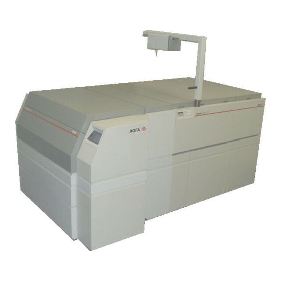
The Avantra 36 and 44 are members of the Avantra family of high-end laser based PostScript image recorders. They build upon the Avantra 20/25 advanced capabilities and add new features. The Avantra 36/44 line is especially designed for users requiring large format output, such as packaging and posters. Both systems support the high quality imaging requirements needed for CristalRaster. - Page 21 Introduction The following illustrations show the imagesetter with all the OLP options installed and attached. The Avantra 36/44 imagesetter, buffer, and crane. –Imagesetter. –Crane. –Buffer –On-line Processor (OLP). The bridge. – Top cover. – Bridge. – Light shield. Introduction xxi...
-
Page 22: Glossary Of Acronyms
Glossary of Acronyms Introduction This glossary contains acronyms used in the Avantra 36/44 Imagesetter Service Manual and in scanning environments in general. For more information about an acronym, see the index in this manual. Agfa Light Diode Board APIS Agfa Print Engine Interface Standard... - Page 23 Avantra 36/44 Service Manual Printed Circuit Board Phase Lock Loop Pulse Width Modulation Read Access Memory Raster Image Processor Read Only Memory Sensor Driver Module Spot Generation Modules Serial Peripheral Interface TSDM Take-up Side Media Transport Take-Up xxiv Glossary...
-
Page 24: Section 1: Imagesetter
Section I: Imagesetter... -
Page 25: Chapter 1: Imagesetter Installation Procedures
• Customer Application Training Customer Pre-site Checklist The customer should use the following pre-site checklist to ensure that the intended installation site is properly prepared to receive and install the Avantra 36/44 image- setter. • Power Requirements The customer must provide a separate (isolated) three wire 115/230 VAC grounded power line. - Page 26 No overhead lights should appear directly over the system. The system should not be located near windows with direct sunlight. The floor where the Avantra 36/44 imagesetter is to be placed must meet the industrial standard for weight per square foot (100 lbs/sq.ft.).
- Page 27 Film Processor Requirements It is recommended that a customer producing color separations use a deep tank film processor. An AGFA processor is preferred (i.e. RAPILINE 44 OLP and P). The processor must be able to handle media widths of 36inches or greater.
-
Page 28: Service Engineer Installation Procedure
Avantra 36/44 Service Manual • Cables–the system must be located so that the Agfa Print Engine Inter- face Standard (APIS) cable between the Avantra and the RIP is of suffi- cient length. Verify that all network and interface cables are of correct length for other equipment to be installed (e.g., scanners and front-... -
Page 29: Unpacking The Imagesetter
Section I: Imagesetter 1.3.2 Unpacking the Imagesetter Tools Required: A tool kit is packed inside the imagesetter crate. Remove the kit at Step 5 below and check it against Figure 1-1. Figure 1-1 The imagesetter tool kit. –Ratchet. –Ratchet extensions. –Sockets. –Jack Screw. - Page 30 Avantra 36/44 Service Manual Figure 1-2 Removing the outer shipping crate. –Shipping straps. –Top pad. –Spring clips or bolts. –Shipping bolts (2 on each side). –Two crossbars. 6. Remove the parts list and accessory box. Refer to Figure 1-3. Put the acce- sory box aside for the unlocking and installing procedures.
- Page 31 Section I: Imagesetter Figure 1-3 Preparing to remove the plates, diapers and skis. –Parts list package. –Shipping straps. –Accessory box. –End support bolts with washers. –Tool kit. –End plate. –Diaper. 9. Cut the two (2) large tie wraps at the center channel, front and back. Refer to Figure 1-4.
- Page 32 Avantra 36/44 Service Manual Figure 1-4 Removing the diaper and end plates. –One of two tie wraps. –End bolts (3 at each corner). –Diaper (removed). –End plate, 1 at each end (removed). 11. Loosen the two (2) outer channel bolts on either end. Refer to Figure 1-5.
- Page 33 Section I: Imagesetter Figure 1-5 Removing the channel bolts. –Outer channel bolts (3 per skid). Loosen the two bolts at each end first, leaving the center bolt in place. –Inner channel bolts (4 per end channel) connecting the end channels to the imagesetter frame. –Imagesetter frame. –End channel (1 of 2).
- Page 34 Avantra 36/44 Service Manual 15. Cut the two (2) packing straps around the unit to remove the cardboard and plastic covers. Refer to Figure 1-6. Figure 1-6 Removing packing materials from the imagesetter. –Cardboard covering. –Packing straps. –Plastic cover. 16. Open the imagesetter door on the left side. See Chapter 4, Section 4.2.2, Top, Middle, and Bottom Front Panels.
- Page 35 Section I: Imagesetter Figure 1-7 Using the jack screw and plate for raising the imagesetter (left side). –End plate. –Jack screw. –Jack screw (dimpled) plate. –Outer bolt (1 of 2). –Spring clip. –Skid. 19. Turn the jack screw until the unit begins to lift on the plate. Raise the unit only an inch from the ground.
- Page 36 Avantra 36/44 Service Manual 22. Remove the end cap and jack screw from under the unit. WARNING: Block the wheels on the left side of the unit to keep the unit from rolling during the next steps. 23. Open the right side cover on the unit. See Chapter 4, Section 4.2.2, Top, Middle, and Bottom Panels.
-
Page 37: Unlocking And Installing The Imagesetter
The chafe tray is part of the imagesetter installation hardware. The extension platen and related hardware are used when attaching the imagesetter to the buffer. See Avantra 36/44 Buffer Service Manual, Chapter 1. Steps: 1. Remove the foam strips between the front panels and frames. Refer to Figure 1-10. - Page 38 Avantra 36/44 Service Manual Figure 1-10 Removing the packing materials from the front of the imagesetter. –Cardboard packing strips. –Foam packing strips. 3. Remove the cardboard packing and the two (2) plastic inserts near the top of the imagesetter’s back panel. Refer to Figure 1-11.
- Page 39 Section I: Imagesetter Figure 1-11 Removing the packing materials from the rear of the imagesetter. –One of 2 plastic inserts. –Cardboard packing. 4. With the top cover open, remove the four (4) screws in the bridge tie down bracket (red) in the lower left and lower right corners of the bridge foot.
- Page 40 Avantra 36/44 Service Manual Figure 1-12 Removing the tie down bracket. –Bridge tie down bracket. –Four hex screws. —Supply tray. WARNING: Do not lift the bridge unless the system has been put in ‘light mode.’ To initiate light mode, the imagesetter must first be turned on.
- Page 41 Section I: Imagesetter Figure 1-13 Removing the lower media transport retainer bracket. –Transport retainer bracket. –Two bracket hex screws. –Supply tray. 8. Locate the two upper media transport Retainer Brackets (gray) in the upper right and left of the exposed unit. Refer to Figure 1-14. Remove the ship- ping screw at the center of the bracket.
- Page 42 Avantra 36/44 Service Manual Figure 1-14 Preparing the media transport retainer bracket. –Media transport retainer bracket (one of two). –Shipping screw (one of two),between two lockdown screws. 9. Locate the take-up light shield in the center of the unit. Refer to Figure 1-15.
- Page 43 Section I: Imagesetter 10. Insert the chafe tray provided (see Figure 1-9) by hooking the ends into the slots at the bottom and to each side of the exposed area. Refer to Figure 1- Figure 1-16 Inserting the chafe tray. –Chafe tray.
- Page 44 Avantra 36/44 Service Manual Unlocking the Carriage 1. Open the left and right side covers. See Chapter 4, Section 4.2.1, Right/Left Side Covers. 2. Remove the light shields, left and right, by pulling each of the five (5) latch knobs out and twisting them so that they rest outside of the lock slot. Refer to Figure 1-17.
- Page 45 Section I: Imagesetter 3. Remove the 3/8¨ hex bolt in the end stops at each side, left and right, of the carriage. Refer to Figure 1-18. Figure 1-18 Unlocking the carriage. –One of 2 end stops (1 on each carriage end). –Center stop. –Foam pad.
-
Page 46: Checking The System
Avantra 36/44 Service Manual Checking the System The following procedures describe how to verify correct system operation and con- nect properly to the Image Control System (ICS). Steps: 1. Power the the system on and monitor the progress of the power-up boot diagnostics on the control panel. - Page 47 Section I: Imagesetter • Power cycle the system. As the system boots, an icon appears on the control panel as shown in Figure 1-19. Press the icon. This initiates an automatic dial-out sequence to the Remote Diagnostic Center. SelectSet Avantra Diagnostics Startup V.1.01 O 2 @ @ @ @ @ @ @ @ @ @ @ @ @ @ @ @ @ @ @ @ @ @ @ @ @ 6 K ? h e...
-
Page 48: Customer Application Training
Avantra 36/44 Service Manual 8. After the density has been checked/adjusted for each resolution, run the Avantra Installation files. Run the following list of files: • 50% @ 1200, 1800, 2400, 3600 • m 100/85% @ 2400, 3600 • m Scale/Fid @ 240 Run the focus test file and adjust as necessary. - Page 49 Section I: Imagesetter The training should include the following instructions: • Daily/weekly system maintenance routines • Functionality of the control panel • Daily operating procedures • Defining cassette parameters • Determining proper exposure settings • Setting system defaults • System error reporting and brief descriptions of possible solutions to error conditions, which results in reduced numbers of unnecessary service calls Installation 1-25...
-
Page 50: Chapter 2: Imagesetter Functional Analysis
Functional Analysis Introduction This chapter presents an overview of the Avantra 36/44 imagesetter. Described here are the functions of all major subsystems, modules and submodules within the sys- tem. This chapter covers both electrical and opto-mechanical subsystems, showing the major functional block diagrams for each. - Page 51 Avantra 36/44 Service Manual • Power Supply • Additional Voltages • Power Distribution • Power Good • Optical System Overview • Spot Generation Module • Laser Diode Mount • Polarizer • Spot Size Changer • Spot Forming Lens • Weak Lens •...
-
Page 52: System Overview
The Avantra is a floor-standing unit. It has a simple, language independent control panel, utilizing icons and a touch screen display. The system is designed to inter- face via the Agfa Print Engine Interface Standard (APIS) to a single Image Control System (ICS), which is packaged separately from the imagesetter. -
Page 53: Electronics Packaging
Avantra 36/44 Service Manual The OCP module, which contains a dedicated micro-controller, is the main control- ler of the system. User commands originating from the RIP and/or the operator are verified, parsed and either acted upon by the OCP or passed to the DEC. The pars- ing process includes breaking the macro language of the user into a micro language that is more easily implemented within the engine controller. - Page 54 Section I: Imagesetter 2.3.2.1 DIAG Micro-controller • System initialization at reset • Power-up tests • System diagnostics • Handling SPI communication primitives • Loading correction tables • Debugging monitor mode • Monitoring SPI communications 2.3.2.2 DEC K-1 Micro-controller • Diagnostic tests •...
- Page 55 Avantra 36/44 Service Manual 2.3.2.5 DEC K-1 FLASHROM • Main DEC software 2.3.2.6 DSP FLASHROM • DSP main program • Correction tables 2.3.2.7 OCP FLASHROM • OCP main program • Control panel icons 2-6 Functional Analysis...
-
Page 56: Digital Engine Controller (Dec)
Section I: Imagesetter DEC K1 DSP FLASHROM Micro-controller DEC Machine Parameters DSP Main Program 1. Image/Focus Parameters 2. Media Parameters 3. DSP/PLATE Correction Tables FLASHROM 1. DEC K1 Software OCP EEPROM OCP FLASHROM Micro-controller 1. OCP User Parameters 1. OCP Main Program 2. -
Page 57: Operator Control Panel
Avantra 36/44 Service Manual Buffer Laser APIS Data Driver Control Position Sensors Media Sensors Safety Sensors APIS Commands Engine Micro- On Line Processor Controller User Commands DC Motors Stepper Motors Solenoids Spinner Servo Servo Micro- Controller Carriage Servo (D.S.P.) Media Feed Servo... -
Page 58: Micro-Controller
Section I: Imagesetter The OCP module consists of the following submodules and is shown in the OCP block diagram in Figure 2-3. • 68HC11 Micro-controller • Program/Display FLASHROM • Liquid Crystal Display (LCD) • Keypad Matrix • OLP Serial Interface •... -
Page 59: Liquid Crystal Display (Lcd)
Avantra 36/44 Service Manual The OCP micro-controller reads the program directly from the FLASHROM via one of its I/O ports. The display portion of the ROM can also be read by the micro-con- troller and fed directly into the Liquid Crystal Display interface. -
Page 60: Sensor Driver Module (Sdm)
Section I: Imagesetter The Laser Diode Drive, (LDD), connects to the CSDM. All controlling signals pass from the DEC, through the Flex-Band, and through the CSDM to the LDD. Also see Figure 2-4. Carriage Motor (pancake) Carriage Motor Driver Position Encoder (digital) Velocity Encoder (Analog) Spinner Motor Spinner Motor... -
Page 61: Sdm To Dec Interface
Avantra 36/44 Service Manual • Connects directly to all sensors (except several that connect to the CSDM) and gathers them into matrices of 2 x 6. This allows for a simpler and more orderly system cabling scheme. 2.7.1 SDM to DEC Interface Each SDM has one header connection from the DEC, providing power and two 8- bit data lines for reading sensors and controlling motors. -
Page 62: Laser Driver Module (Ldm)
Section I: Imagesetter Figure 2-5 Sensor grid. –Row 0. –Row 1. –Column 0. –Column 1. –Column 2. –Column 3. –Column 4. –Column 5. Laser Driver Module (LDM) The LDM controls the laser diode current so that the laser diode light output wave- form corresponds to that of the clocked data from the image buffer. -
Page 63: Power Supply
Avantra 36/44 Service Manual Power Supply The power supply is a low voltage switching supply, with non-adjustable outputs. A switch mounted to the side of the power supply configures the input voltages of 110 or 220 volts. The 300 watt power supply generates the following voltages: + 5.0 volts... -
Page 64: Optical System Overview
Section I: Imagesetter 2.10 Optical System Overview The optical system divides into two basic sections: • Spot generation module (SGM) • Spin motor module Several components, which all locate on a sub-base that mounts on the carriage assembly, make up the SGM. The spin motor module also directly mounts to the carriage assembly, which translates through the center of the drum. -
Page 65: Spot Generation Module
Avantra 36/44 Service Manual 2.11 Spot Generation Module The Spot Generation Module (SGM) is a field replaceable unit that mounts to the car- riage assembly. Figure 2-7 illustrates the SGM. The SGM produces a focused laser spot of the proper size, shape and position. -
Page 66: Laser Diode Mount
Section I: Imagesetter 2.11.1 Laser Diode Mount The laser diode mount provides the mechanical interface to mount the laser diode driver module PCB, as well as the laser diodes. Refer to Figure 2-7. This submod- ule also provides precision x and y translations for module-level bow corrections, an angle reference in the z direction of the laser diode for beam ellipticity, and adjustment in the y direction for beam pointing. -
Page 67: Weak Lens
Avantra 36/44 Service Manual 2.11.5 Weak Lens The weak lens, which is a long focal length lens, moves along the optical axis of the SGM to provide for a system level focus adjustment. It mounts between the polarizer and the spot forming lens. A small motor and screw mechanism translates the lens to provide the proper focal length over the entire range of media thicknesses (4 - 12 mils) as well as a system level fine focus adjustment. -
Page 68: Spin Motor
2.12.1 Spin Motor The spin motor is a precision hydrostatic (air bearing) spindle DC servo motor. Refer to Figure 2-8. It runs at a constant velocity of 13,500 RPMs for Avantra 36/44 systems and 20,000 RPMs for Avantra 36S/44S systems. - Page 69 Avantra 36/44 Service Manual Figure 2-9 Carriage assembly. The carriage assembly consists of: • Carriage housing with precision mounting interfaces for the bearing com- ponents • Optical system • Friction wheel drive components The carriage assembly uses a friction drive system with recirculating ball bearings that ride on two rails mounted to the upper structure.
-
Page 70: Linear Bearing Guideway
Section I: Imagesetter Both encoders are high count precision rotary encoders. One of the encoders (ana- log) couples directly to the friction wheel shaft and is used to feed back carriage velocity errors. The other encoder (digital) mounts inside the carriage housing and is preloaded to make direct contact with the guide rail. - Page 71 Brush control is determined by the values loaded in the DEC Image/ Focus/Bridge Menu for film, paper and plate material. NOTE: On the Avantra 36/44 the drivers for the brushes are on the SDM board. On the 36S/44S the brushes are on the carriage board...
-
Page 72: Vacuum System
flappers are in their load (down) or image (up) positions. 2.13.5 Vacuum System The Avantra 36/44 has a multi-port vacuum system. The system contains a 115 volt vacuum pump, transformer, vacuum board, vacuum valves and voltage sensor relay. - Page 73 Avantra 36/44 Service Manual 2.13.5.2 Vacuum Valves The pump vacuum lines attach to valves, which are controlled by the system soft- ware in accordance with the width of the media. Any width below 26 inches causes one of the valves to open. Any width over 26 inches causes both valves to open.
-
Page 74: Media Transport System Overview
Section I: Imagesetter Figure 2-13 The vacuum board and sensor relay. –Vacuum board. –Sensor relay. 2.13.5.4 Vacuum Voltage Sensor Relay This relay senses the voltage when powering on the imagesetter. Refer to Figure 2-13. If the relay senses 220 volts, it configures the transformer for a 115 volt output to the vacuum pump. -
Page 75: Supply Side Mechanics
Avantra 36/44 Service Manual The media transport system handles: • Web fed form • Red sensitive paper • Film • Plate The media feeds through the transport system by means of a nip and one of two rollers on the supply side (one for each supply cassette). The nip and roller push the media through an entrance platen into the supply punch module then down onto the drum surface. -
Page 76: Powered Media Take-Up Cassette
Section I: Imagesetter 2.14.1.4 Drive Rollers The drive rollers load and unload media from either spindle A or B. They are nipped by the spindle A/B gear motor, which is controlled by the spindle A/B sen- sors. 2.14.1.5 Spindle A/B Sensors These two sensors shut off the spindle A/B gear motor when the drive roller is nipped to either A/B drive roller. -
Page 77: Media Punch/Clamp Assembly
Avantra 36/44 Service Manual Figure 2-14 Take-up cassette. –Take-up cassette. –Six cover screws. –Core. –Clutch adjustment screw. In order to accept media, the core is driven enough to open the counter-weight gap. A reflective optical sensor is located in the take-up area. This sensor operates during the drive sequence and signals the exact point that aligns the core gap to the entrance chute. -
Page 78: Take-Up Drive Assembly
Section I: Imagesetter Figure 2-15 Media punch/clamp assembly. –Punch assembly. –Sensor. –Punch assembly motor. All punches operate the same way. A gear motor turns a shaft that actuates a pres- sure plate (clamp) and a rocker mechanism. The rocker assures punch engagement regardless of punch location. - Page 79 Avantra 36/44 Service Manual Figure 2-16 Inner nip drive system. –Inner nip drive system. –Inner nip motor. –Sensor. –Roller. 2.14.4.2 Outer Nip Drive System The outer nip drive system contains the cutter interlock switch, which, when dis- abled, shuts off the cutter. Refer to Figure 2-17.
-
Page 80: Media Cutter Assembly
Section I: Imagesetter The solenoid plunger attaches around the drive roller via a bushing arm. To open (release) the take-up rollers, the solenoids are energized for a pre-determined num- ber of seconds. The solenoid stroke opens a .02" gap between the rollers to disen- gage the take-up drive, but not enough to disengage the drive gear mesh. -
Page 81: Supply Cassette
Avantra 36/44 Service Manual Figure 2-19 Media cutter assembly. –Cutter home switch. –Cutter motor. NOTE: The DC gear motor and the home switch can also be replaced separately. The cutter assembly consists of: • Media platens • Cutter bar •... - Page 82 Section I: Imagesetter The supply cassette consists of: • Cassette housing • Tension roller • Two hub and spindle assemblies Refer to Figure 2-20. Figure 2-20 Supply cassette. –Supply cassette. –Spindle bearing. The cassette housing opens in the center to facilitate the loading of media. The ten- sion roller mounts on the upper half of the housing and keeps the media tightly wrapped on its core, while the media is either being pulled out or rewound.
-
Page 83: Humidifier Option Overview
Avantra 36/44 Service Manual 2.15 Humidifier Option Overview This section describes the mechanical, electrical and software characteristics for a field installable humidifier sub-system. 2.15.1 General Description The humidifier creates a 50% (±5%) relative humidity in the drum 15 minutes after the humidifier is turned on. -
Page 84: Humidifier Electronics Module
Section I: Imagesetter The humidifier system is closed loop. The inlet port receives drum air, which passes through an air filter. The system then draws the filtered air through a water wick whose bottom section is immersed in water contained in an internal resevoir. Next, through the process of capillary action, the water draws up and saturates the wick. -
Page 85: Fan Control Circuit
Avantra 36/44 Service Manual 2.15.3.1 Power The fan power connector (J3) located on the right door supplies the +24 volts used on the board. NOTE: The door fan is not required when the system has a humid- ifier installed. The (J3) connector supplies power to the wiring harness, which in turn supplies power to the humidifier electronics module. -
Page 86: Interface Connections
Section I: Imagesetter The voltage comparator is structured as an oscillator with the frequency controlled by the sensor. This sensor, a capacitor, varies its capacitance in relation to the amount of moisture in its environment. As the moisture level increases, the sensor capacitance also increases causing the oscillator frequency to decrease. -
Page 87: Humidifier Option: Warnings And Indications
Avantra 36/44 Service Manual 2.16 Humidifier Option: Warnings and Indications The Run and Pause screens display the humidifier enable icon when the humidifier is enabled. 2.16.1 Humidity Low Indicator When switching on the imagesetter, the OCP displays the humidity low icon, if humidity is below the desired level. -
Page 88: Chapter 3: Imagesetter Diagnostics And Vacuum System Troubleshooting Guide
Chapter 3: Imagesetter Diagnostics and Vacuum System Troubleshooting Guide Introduction This chapter describes the diagnostic tools necessary for testing and verifying the functionality of the imagesetter. These tools include boot-up diagnostics (in ROM) and the Avantra Diagnostic Program (AVDIAG), which is PC based. This chapter also contains a troubleshooting guide for diagnosing and repairing problems with the vacuum pump system. -
Page 89: Power-Up Boot Diagnostics
Avantra 36/44 Service Manual NOTE: PC Imager software is a tool designed to aid the service engineer when verifying image quality and communication as they relate to a raster image processor (RIP). This soft- ware is described in the PC Imager User’s Manual P/N 580024-001. -
Page 90: Power-Up Boot Sequence
Section I: Imagesetter Because the Avantra is a multi-controller system, it provides two levels of tests: • Level One (core tests) –executed by each micro-controller as it is taken out of reset by the DIAG. The test purpose is to verify that each micro-controller and its hardware domain are functional. - Page 91 Avantra 36/44 Service Manual Next, the OCP is taken out of reset. SPI communication tests execute between the DIAG and the OCP. If the tests are successful, the OCP firmware and loader revi- sion levels appear on the control panel, and the DIAG tells the OCP to update the progress bar.
-
Page 92: Error Reporting
Section I: Imagesetter 3.2.3 Error Reporting If any tests fail, the DIAG micro-controller reports the error via the diagnostic serial port on the DEC board or, if possible, on the operator control panel. Also, if a modem is present and enabled, the diagnostics dial a telephone number that has been pre-stored in the modems configuration NVRAM. - Page 93 Avantra 36/44 Service Manual 3.2.3.3 LED Error Reporting An LED on the DEC board indicates whether the boot has successfully completed. A red light indicates either that the boot sequence has not been completed or an error condition exists. When the LED goes out, the boot sequence has completed with no errors.
- Page 94 Section I: Imagesetter 3.2.3.9 OCP Register Test To test the OCP register, a two byte pattern is written into it. The first byte is the real data, and the second byte is used to retrieve the feedback. 3.2.3.10 FLASHROM Cheksum The flash memory stores the 2400 and 3600 dpi correction table entries and DSP code.
- Page 95 Avantra 36/44 Service Manual 3.2.3.14 DEC Micro-controller Test Descriptions The following list describes the tests performed on the DEC micro-controller during the boot sequence. • Internal ROM Checksum– performs a rotate and add checksum. Bytes are added to a 16-bit sum, after the sum has been rotated right one posi- tion.
- Page 96 Section I: Imagesetter • Supply Motors Test– to test the motors, the supply DAC is set to 500 millivolts and one of the motors under test is selected by addressing it via port C. The supply motor DAC controls four motors: •...
- Page 97 Avantra 36/44 Service Manual 3.2.3.15 DSP Micro-controller Test Descriptions The following list describes the tests performed on the DSP micro-controller during the boot sequence: • RAM Test– since the DSP runs out of RAM, it is not useful to run a check- sum on the code.
-
Page 98: Automatic Dial-Out Feature
Section I: Imagesetter 3.2.3.16 OCP Micro-controller Test Descriptions The following list describes the tests performed on the OCP micro-controller during the boot sequence: • External ROM Checksum– performs a rotate and add checksum on the entire FLASHROM. Bytes are added to a 16-bit sum, after the sum has been rotated right one position. - Page 99 Avantra 36/44 Service Manual 2. Modem Dial-out After the initialization string has been responded to, the modem dials out the pre-stored telephone number in the modem’s configuration profile. The modem stores up to four telephone numbers in non-volatile memory, 0 - 3. The telephone number must be stored in location 1. The firmware issues the dial command ATDS=1 to the modem.
-
Page 100: Boot Error Codes
Section I: Imagesetter 3.2.5 Boot Error Codes Table 3-1 lists the Avantra boot error codes. Table 3-1 Boot error codes. Error Code Description Spinner Overspeed error Door Open during Boot OCP Hardware Handshake error DEC flash ROM is blank Cannot switch K-4 to master mode DSP hardware handshake error Cannot Set DACs to zero Carriage DAC failed to go low (-4 volts) - Page 101 Avantra 36/44 Service Manual Error Code Description Cannot command DSP to move carriage in reverse No times 4 carriage encoder pulses Missing (not enough) times 4 encoder pulses Supply sensor/cable not connected Supply punch motor on failed Supply punch motor off failed...
-
Page 102: Ocp Run-Time Application Errors
Section I: Imagesetter 3.2.6 OCP Run-Time Application Errors Table 3-2 OCP Run-Time Application Errors Error Code Description Carriage Jam Cutter Jam Out of Media No Take-Up Cassetts Media Jam Take-Up Punch Jam Cutter Off Sensor Take-Up Cassetts Mismatch Page-Length Error Hardware Error Left Door Open Missed Breakpoint... - Page 103 Avantra 36/44 Service Manual Error Code Description Bridge Comm Error Bridge Jam Before Center Sensor Bridge Jam at Processor Bridge Jam Before Clear Bridge Motor Jam Bridge Has No Media at Input Processor Off-Line: Fatal Processor Not Communicating Processor Top Cover Open...
-
Page 104: Avantra Diagnostic Program (Pc)
RS-232 serial port of the PC and the imagesetter’s remote diagnostic port. Information is exchanged and functions executed by sending com- mands to the imagesetter. These commands are loosely based on the Agfa Print Engine Interface Specification (APIS) but do not follow that specification fully. The Avantra Diagnostic Program can be used locally with a direct connection or remotely via a modem. -
Page 105: Software Installation
Avantra 36/44 Service Manual Direct Connect: • Avantra diagnostic software 700594-1003* • 9-pin female connector (PC end) 78448-015 • 25-pin male connector (imagesetter end) 78448-016 • Cable 78448-008 * This may not be the latest revision of software. Refer to OMNI Bulletin Board for latest revision of AVDIAG Program. -
Page 106: Starting The Program
Section I: Imagesetter 3.3.3 Starting the Program The following procedure describes how to load, initialize, and start the Avantra Diagnostic Program (AVDIAG): 1. Insure that the Avantra diagnostic software has been properly loaded onto the PC as described in Section 3.3.2. 2. - Page 107 Avantra 36/44 Service Manual 3.3.3.1 User Interface The top bar menu contains the following groups of sub-menus: • TEST • ALIGN • UTILITIES • FLASHROM • EXIT Test Menu Test menu items are: • Selectable Tests • Download CMD File •...
- Page 108 Section I: Imagesetter DEC Tests Test Function Register Test Test SPI registers (offgate, ongate, vacuum, vacuum 2) DSP Echo Test Verify DEC - DSP communications Carriage Test Verify encoder feedback from carriage movement Supply Motor Test Supply Motor on/off bit tests at 0 current Take-up Motor Test Take-up motor on/off bit tests at 0 current Video 1 Int Test...
- Page 109 Avantra 36/44 Service Manual DAC RAMPS NOTE: These tests can only be performed in manufacturing during board test. Running these tests on the PC will post an error. • All Ramps On • All Ramps Off • Density DAC •...
- Page 110 Section I: Imagesetter MEDIA TESTS NOTE: To actually see the motors moving, you need to run these tests in continuous mode with a pass count of 10. Test Function Cutter Executes a Media take-up Punch Take-up Punch Execute a Head Clamp-Punch-Home sequence Supply Punch Execute a Tail Clamp-Punch-Home sequence Nip Solenoid...
- Page 111 Avantra 36/44 Service Manual BOOT TESTS Test Function Diag-Ocp Hadshk Test Verify Diag-Ocp communications in Master Mode Offgate Reg Test Test SPI Offgate Register Ongate Reg Test Test SPI Ongate Register Vacuum 1 Reg Test Test SPI Ongate Register Vacuum 2 Reg Test...
- Page 112 Section I: Imagesetter CLOSE LOG FILE This closes the opened log file above. Download File • Command Files This program allows the creation of ASCII command files containing a sequence of commands to be sent to the imagesetter's remote diagnostic port.
-
Page 113: Functions
Avantra 36/44 Service Manual Command File Format The following is the format of a typical command file. # a comment not to be executed # This file will first Home the carriage and then # slew the carriage between 8000 and 30000, repeating 10 times... - Page 114 Section I: Imagesetter ALIGN MENU Imagesetter Configuration This menu item displays a window containing the currently set options and changes any option setting and saves the configuration to the imagesetter. This set- ting stores as a machine parameter in DEC EEPROM. The currently settable options are: Machine Type....Set Machine ID to all the different Avantra engines Options...
- Page 115 Avantra 36/44 Service Manual SGM-A/B Mod Align This menu item controls the alignment of the SGM parameters. The SGM-A/B Mod Align Menu appears as follows: Spinner......ON/OFF Beam......ON/OFF (BM) Resolution.... 3600 (BM) Gate Start....0 (BM) BOL Position..0 (BM) Gate Length..
- Page 116 Section I: Imagesetter Defaults: Resolution will be set to 3600 Gate Start to 0 Gate Length to 25 Aperture to 3600. The resolution will automatically change to the aperture's value. Carriage Alignment This menu item allows the alignment of the carriage encoders. This function exe- cutes a test on the DSP, reads in the values resulting from that test, displays the val- ues, and calculates new encoder constants and writes the new encoder constants to DEC EEPROM.
- Page 117 Avantra 36/44 Service Manual DEC (Image/Focus/Bridge) Parameter Value Value Parameter Value Parameter BOL Offset..Polarizer Home..Brdg Max. Torque Carriage Home..Focus Position..Buffer Med Spd..11421 PWM @1200..Focus Steps/Mil... Bridge On Delay..PWM @1800..Focus Motor Rate 15300 Ubr FastSp Thin...
- Page 118 Section I: Imagesetter Write new values to the imagesetter by typing in the appropriate parameter. Listed below are the parameters and defaults. Bridge Max Torque The maximum torque of the upper bridge motor. Defaullt is 250. Increasing the calue increases the torque.
- Page 119 Avantra 36/44 Service Manual Variable Film Film Film Film Film Film Film Film Paper Paper Media (3-5) (3-5) (3-5) (6-8) (6-8) (6-8) (9-12) (9-12) Parameter Narr Wide Narr Wide Narr Wide Narr Wide S-Feed Current T-Compress Curr T-Compress Speed Midpoints (.01”) M4....2400...
- Page 120 Section I: Imagesetter 2. The “T-Compress Speed” is really the compression speed for both supply and take-up servo motors. The supply servo uses a percentage of the “T- Compress Curr” value. The percentage amount is specified in the “S Cmp Curr Rtio”...
- Page 121 Avantra 36/44 Service Manual Media Parameter Range Definitions T/U Cassette Align Current (0 - 255) Current for takeup cassette motor to move core to home position. T/U Cassette Wind Current (0 - 255) Torque of takeup cassette motor (Forward Direction).
- Page 122 Section I: Imagesetter DSP/Plate Selecting DSP displays a dialog box that shows the current Plate/DSP parameters stored in the imagesetter. These parameters are in DEC EEPROM. The software retrieves them from EEPROM upon entering this menu selection. New values are written to the imagesetter by typing in a new value in the appropriate parameter.
-
Page 123: Settings
Avantra 36/44 Service Manual NOTE: DSP numbers 0, 1, 2, and 3 are set after executing the Avdiag “Carriage Align” test. DSP numbers 4 and 5 are set after executing the Avdiag “Feed Motor Cal” test. OCP User Parameters User Parameters NOTE: To view the following parameters you must first down load... - Page 124 Section I: Imagesetter Plate Overlap (108) 1080 PL-12 Rewind Lev (109) Feed High Res (63) Interpage High Res (64) Feedcut High Res (65) Plate Mode (67) Cassette Parameters The cassette parameters contain the customer settings for the five cassettes. Write new values to the imagesetter by simply typing in a new value in the appropriate parameter.
- Page 125 Avantra 36/44 Service Manual Firmware Revisions Selecting Firmware Revs displays a dialog box that lists the firmware revision levels installed in the imagesetter currently connected. Avantra Firmware Revisions DEC Firmware (K4/K1 FlashROM DSP Firmware (DEC FlashROM) OCP Firmware (OCP FlashROM...
- Page 126 Section I: Imagesetter Display Sensors The Display Sensors menu item actively monitors the state of all sensors and switches in the imagesetter. With this menu, the user activates or deactivates a sen- sor and monitors the state of the sensor on the display (e.g., moving a jam wheel causes the state of the sensor to display on and then off as the wheel moves through the sensor).
- Page 127 Avantra 36/44 Service Manual Row 4 Row 3 Row 2 Row 1 Row 0 Figure 3-1 Avantra sensor grid. RowCol 00 = Humidity RowCol 01 = Left flapper load (down) sensor RowCol 02 = Supply jam detector RowCol 03 = Left flapper image (up) sensor...
- Page 128 Section I: Imagesetter Carriage Motion This item moves the carriage in the same manner as it operates during imaging. The Carriage Motion Menu appears as follows: Spinner On Spinner Off Carr. Home Pos. (EEPROM) Home Carriage Carr. Slew to Position Image Start Image End (EOT) Carr.
- Page 129 Avantra 36/44 Service Manual Menu Item APIS Command Get Status {MXSS} Abort {MXDS0180} Shut Down Media {MXDS0181} Supply Feed {MXDS0184} Image Feed {MXDS0185} Reverse Feed {MXDS019F} Supply Torque ON {MXDS0196} Supply Torque OFF {MXDS0197} Takeup Cut {MXDS0189} Open Nips {MXDS018E}...
- Page 130 Section I: Imagesetter Bridge Primitives Used to test the bridge. The user must turn the bridge on before running any of the tests below. These tests were not designed to test the complete functionality of the bridge. The two sensors (entrance and exit) are not tested during any of the primi- tive tests.
- Page 131 Avantra 36/44 Service Manual Utilities Menu The utility menu contains various utility commands and functions used by the AVDIAG, such as reset commands, imagesetter configuration, port configuration, and modem utilities. The following describes each menu selection. New Engine/Restart This menu selection prepares an imagesetter to respond to diagnostic commands.
- Page 132 Section I: Imagesetter Config Comm. Port This menu selection selects which communication port on the PC to use when communicating to the imagesetter. The choices are: COM1-NONE, COM1-XON/XOFF COM2-NONE COM2-XON/XOFF or the internal CGEN Serial Port ATMSCC Other communication ports are not supported (i.e., com3 or com4). Modem Functions This menu selection brings up a dialog box with a list of modem functions per- formed by the AVDIAG:...
- Page 133 Avantra 36/44 Service Manual Edit Phone File This item enters a new phone number or modifies an existing number located in the AVDIAGs phone file. The phone file is a small database of names and phone numbers used by the AVDIAG when dialing out.
- Page 134 Section I: Imagesetter Edit File Selecting Edit File allows a text file to be edited using the DOS editor without exit- ing the AVDIAG program. When edit file is selected, a dialog box appears with prompts for entering a filename to edit. Type in the desired filename and press ENTER.
- Page 135 Avantra 36/44 Service Manual Set Real-Time Clock Month Date Year Hour Minute FLASHROM The download files should reside in a common subdirectory such as Download. Prog DSP/CORR Programs the DEC FLASHROM. Prior to programming the FLASHROM, the DEC DSP and the DEC CORR must be saved.
-
Page 136: Save And Restore System Parameters
Section I: Imagesetter 3.3.4 Save and Restore System Parameters 3.3.4.1 Save/Restore DEC Machine Parameters Use this procedure to save DEC machine parameters to the PC or to restore DEC parameters from a PC back to the system. The parameters saved/restored reside in the DEC micro-controller’s EEPROM and include: •... - Page 137 Avantra 36/44 Service Manual To Restore: 1. Connect the PC to the diagnostic serial port of the system. 2. Turn the system on and allow the boot cycle to complete. 3. Launch the AVDIAG Program from the PC. 4. Under the ALIGN menu, select DEC Machine Parameters and press ENTER.
- Page 138 Section I: Imagesetter 3.3.4.2 Save/Restore DEC DSP and DEC Correction Tables (DEC FLASHROM) Use this procedure to save DEC DSP and DEC correction tables or to restore them to the DEC FLASHROM. To Save: 1. Connect the PC to the diagnostic serial port of the system. 2.
- Page 139 Avantra 36/44 Service Manual To Restore: 1. Select FLASHROM and then Prog DSP/CORR. 2. Select RAW. 3. Select the filename saved in Step 9. This was the DSP file saved in the save procedures above. 4. Select the correction table for this system that was saved in Step 6 above.
- Page 140 Section I: Imagesetter 4. Under the ALIGN menu, select OCP User Parameters and press ENTER. A dialog box appears: Loading OCP EEPROM User Parameters and OCP EEPROM Cassette Parameters into memory. Select Y in the dialog box. The OCP parameters load up to the PC. 5.
- Page 141 Avantra 36/44 Service Manual 3.3.4.4 Program OCP FLASHROM Use this procedure to load the OCP software from a PC into the OCP’s FLASHROM. The software to be loaded must reside in the Download directory in the PC. NOTE: Prior to programming, the FLASHROM is automatically erased.
- Page 142 Section I: Imagesetter 3.3.4.5 Program K1 FLASHROM Use this procedure to load the DEC. K1 firmware from a PC into the DEC. K1 FLASHROM. The software to be loaded must reside in the Download directory in the PC. NOTE: Prior to programming, the FLASHROM is automatically erased.
- Page 143 Creating Correction Tables The Avantra has twelve Correction Tables. Ten of the twelve tables are identical for all Avantras (Avantra 20/25, Avantra 36/44, Avantra 36S/44S, and Avantra 30). The two tables that are different for each system are the Density Variation (DQ) files and the Linearity (L) files.
- Page 144 Section I: Imagesetter These Default Correction Tables, with the Density Variation and Linearity files, con- tain all the information to make up the Correction Table for each of the Avantra sys- tems. Manufacturing runs two files (a “Density Variation” file and a “Scale” file) which merge with the “Default Correction Table”...
- Page 145 (no AV30s with 20K spin motors). Avantra - 30 @ 30K (AV30 with 30K spin motors). Avantra - 36/44 @ 20K (for Avantra 36/44 “S” systems). Avantra - 25 @ 30K (for Avantra 25 “S” systems). These messages will appear on the PC: PROCESSING DENSITY FILES Using program defaults fit constraints...
- Page 146 Section I: Imagesetter 5. Type “Y” NOTE: This will only appear if there are “D” files on the floppy disk. The new “DQ” files will create new “D” files). This information will appear on the PC: Processing input file a:\dqxxxxxh.001 Largest fit error is x.xxxxxx.
- Page 147 Avantra 36/44 Service Manual NOTE: This writes a new Correction Table to your Avantra directory. The PC displays: Copy COR_HEX to a:? (Y/N) 6. Type “Y”. (This copies the new Correction Table to the “A” floppy drive in the PC).
-
Page 148: Remote Diagnostics
Section I: Imagesetter Remote Diagnostics This section describes the equipment requirements, modem configuration and pro- cedures involved in making a remote connection to an Avantra. 3.4.1 Equipment Requirements A remote connection to an Avantra requires the following equipment. CAUTION: If equipment used to make the remote connection is other than that recommended, unpredictable results may occur. - Page 149 Avantra 36/44 Service Manual Avantra Modem Specifications Data Rate: 2400 BPS or faster Data Compression: CCITT V.42BIS, MNP Class 5 Data Correction: CCITT V.42, MNP Class 2-4 Compatibility: CCITT V.42BIS/V.42/V.22BIS/V.22/V.21/ V.29/V.27 Bell 212A, 103 Command Support Hayes extended AT Command set...
-
Page 150: Hardware Configuration
Section I: Imagesetter 3.4.2 Hardware Configuration This section describes the configuration for both the remote and local modems, as well as the interconnection of all necessary hardware. Imagesetter Modem Configuration: The remote modem recommended is a GVC 2400BPS Fax/Modem, Model # FMM9696/24V. - Page 151 Avantra 36/44 Service Manual NOTE: Remote configuration of this modem is not supported. Configuration must be done at the time of installation. Other modems may support this feature. Refer to manufacturer's documentation. After the modem has been configured, store the settings in the active configuration profile (usually 0) with the following command: AT&W0...
- Page 152 Section I: Imagesetter Local Modem Configuration: The recommended local modem connected to the PC is also a GVC 2400BPS Fax/Modem. If the remote and local modems are the same, command compatibility, data compression, and data correction features should operate properly. Other modems can be used but they must meet the requirements in Table 3-5 and Table 3-6.
- Page 153 Avantra 36/44 Service Manual 3. Plug the telephone line into the modem jack marked LINE. If desired, plug the telephone into the modem jack marked PHONE. 4. Plug the power connector into the modem and plug the AC/DC adapter into an AC outlet.
-
Page 154: Vacuum System Troubleshooting Guide
4. Call the customer site on the voice line to inform them that the Avantra is back on line. Vacuum System Troubleshooting Guide The following is an aid to troubleshooting the Avantra 36/44 vacuum system. Refer to the troubleshooting chart in Figure 3-2 when working with the following proce- dures. - Page 155 Avantra 36/44 Service Manual 4. If the pump still fails to operate, check the vacuum pump fuse: a. Turn the system off, unplug it. b. Locate the fuse holder on the outside of the electronics box (see Sec- tion 4.8, Vacuum in Chapter 4, Imagesetter Component Removal/ Replacement Procedure).
- Page 156 Section I: Imagesetter Figure 3-2 Vacuum system troubleshooting flowchart. Diagnostics 3-69...
- Page 157 Avantra 36/44 Service Manual Figure 3-3 Transformer housing assembly. 3-70 Diagnostics...
-
Page 158: Volt Sensing Relay Adjustment Procedure
Section I: Imagesetter 6. If the voltage reading is wrong, check the voltage coming into the solid state relay (SSR). See Figure 3-3. Using a DVM, measure the AC voltage across the following two points: At 110 V ⇒ 110 V Pin 2 (solid state relay) At 220 V ⇒... - Page 159 Avantra 36/44 Service Manual 3. Locate the volt sensing relay. See Figure 3-3. Locate the green LED and two adjustment screws on top marked: PICK UP and DROP OUT. 4. Turn each adjustment counterclockwise to the MIN setting. 5. Plug in the system and, while monitoring the green LED on top of the volt sensing relay, turn the system on.
-
Page 160: Chapter 4: Imagesetter Component Removal/Replacement Procedures
Chapter 4: Imagesetter Component Removal/Replacement Procedures Introduction This chapter describes the procedures for removing and replacing components in the Avantra 36/44 imagesetter. Topics covered are: • Covers • Right/Left Side Covers • Top, Middle and Bottom Front Panels • Electronic Enclosure Cover •... - Page 161 Avantra 36/44 Service Manual • Intake Fan • Carriage Drive Removal/Replacement Procedures • Carriage Transfer Tool Installation • Carriage Assembly • Opto-mechanical Removal/Replacement Procedures • Light Shields (Right and Left) • Spin Motor Module (SMM) • Spot Generation Module (SGM) •...
-
Page 162: Covers
Section I: Imagesetter Covers The following describes how to remove the covers and panels. 4.2.1 Right/Left Side Covers Tools Required: None Remove: 1. Open the top cover at the front of the imagesetter. Figure 4-1 Imagesetter with front top cover open. Removal and Replacement 4-3... - Page 163 Avantra 36/44 Service Manual 2. Loosen the thumb screw located on the inside of the imagesetter. Refer to Figure 4-2. Figure 4-2 Thumb screw location. –Side Cover. –Thumb screw. 3. Swing the left or right side cover out at a right angle from the system.
-
Page 164: Top, Middle And Bottom Front Panels
Section I: Imagesetter 4.2.2 Top, Middle and Bottom Front Panels Tools Required: None NOTE: The bottom panel is not normally removed. Remove: 1. Lift the bottom segment of the top cover. Refer to Figure 4-3. Figure 4-3 Front of imagesetter. –Front cover. - Page 165 Avantra 36/44 Service Manual 2. Lift the top panel up, releasing it from the lock slots on either side, and pull straight out. Refer to Figure 4-4. Figure 4-4 Top panel lock slots. –Top panel. –Top lock slots. 4-6 Removal and Replacement...
- Page 166 Section I: Imagesetter 3. Do the same for the middle panel, being careful to clear it from its lock slots on the sides. Refer to Figure 4-5. Figure 4-5 Middle panel lock slots. –Front panels (top and middle). –Top panel lock slots. –Middle panel lock slots.
-
Page 167: Electronic Enclosure Cover
Avantra 36/44 Service Manual 4.2.3 Electronic Enclosure Cover Tools Required: 1/4" nut driver Remove: NOTE: The electronics enclosure is located inside the right side cover. 1. Open the right side cover. See Section 4.2.1, Right/Left Side Covers. 2. Remove the three (3) 1/4" hex screws at the bottom of the electronics enclosure. -
Page 168: Media Transport Removal/Replacement Procedures
Section I: Imagesetter Media Transport Removal/Replacement Procedures The following describes the media transport removal/replacement procedures. 4.3.1 Take-up Light Shield 1. Raise the front top cover. 2. Remove the top and middle panels. See Section 4.2.2, Top, Middle and Bottom Front Panels. 3. -
Page 169: Outer Take-Up Drive (Nip) Assembly
Avantra 36/44 Service Manual 4.3.2 Outer Take-up Drive (Nip) Assembly Tools Required: Flathead screwdriver Remove: 1. Unload the media and turn the system off. 2. Open the top cover. 3. Remove the top and middle front panels. See Section 4.2.1, Right/Left Side Covers. -
Page 170: Inner Take-Up Drive (Nip) Assembly
Section I: Imagesetter Replace: 1. Reverse the above instructions to re-install the outer take-up drive assem- bly. 2. The take-up drive assembly should be checked for proper operation before the outer covers are installed. 3. After installing the outer take-up drive assembly and light shield, turn the system on and launch the AVDIAG program from your PC. - Page 171 Avantra 36/44 Service Manual 6. Disconnect the power plugs from the motor. Refer to Figure 4-9. NOTE: For purposes of replacement, the power sockets are marked: 1 = red wire; 2 = brown wire. Refer to Figure 4-9. Figure 4-9 Inner take-up drive (nip) assembly.
- Page 172 Section I: Imagesetter 10. Follow the sensor cable up to the take-up SDM board on the right side of the imagesetter. Unplug the sensor cable at its connector (J6) on the board. Refer to Figure 4-10. 11. Using a 3/16" allen wrench, remove the four (4) bolts, two (2) on each side of the inner take-up (nip) assembly.
-
Page 173: Inner Take-Up Drive (Nip) Motor
Avantra 36/44 Service Manual 5. Enter Display Sensors from the Align menu and check the operation of the take-up jam sensor. The take-up jam sensor can be checked by inserting a piece of film down the right side of the take-up cassette platform until the sensor wheels move, which causes a change in status. - Page 174 Section I: Imagesetter 8. Cut the tie wraps on the motor. Refer to Figure 4-11. Figure 4-11 Inner take-up drive (nip) motor assembly –Inner take-up drive motor assembly. –Two 1/4 " hex screws. –Bracket. –Tie-wrap . –Motor gear. –Allen screw. 9.
-
Page 175: Take-Up Jam Sensor
Avantra 36/44 Service Manual Replace: 1. Install the take-up drive motor using the two (2) 1/4" bracket screws removed in Step 11 in the removal procedure above. Refer to Figure 4-11. 2. Install the motor gear. Refer to Figure 4-11. - Page 176 Section I: Imagesetter Figure 4-12 Inner take-up (nip) jam sensor. –Inner take-up drive (nip) assembly. –Take-up jam sensor. –1/4" hex head screw in tie clamp. –Two 1/4" hex head screws on bracket. –1/4" hex nut on sensor. 4. Using a 1/4" nut driver, remove the 1/4" hex head screw holding the tie clamp.
-
Page 177: Take-Up Punch Assembly
Avantra 36/44 Service Manual Replace: 1. Install the new jam sensor to the Jam Sensor bracket. Do not tighten the screw. Refer to Figure 4-12. 2. Install the jam sensor bracket into the inner take-up drive assembly. Refer to Figure 4-12. - Page 178 Section I: Imagesetter Figure 4-13 Take-up punch assembly. –Take-up punch assembly. –Take-up punch chafe pan. –Three chafe pan standoffs. –Scribe marks (left and right). –Three vacuum tubes. –Two 3/16" hex bolts. –Sensor motor connector. –Punch shoe (DO NOT REMOVE). 4. Remove the three (3) standoffs securing the chafe direction shield attached to the front of the punch assembly.
-
Page 179: Cutter Assembly
Avantra 36/44 Service Manual 7. Remove the two (2) 3/16" hex bolts securing the take-up punch assembly to the outer drum surface. Refer to Figure 4-13. 8. Remove the punch assembly from the system. Replace: 1. Install the punch assembly to the scribe marks. Refer to Figure 4-13. - Page 180 Section I: Imagesetter Figure 4-14 Cutter assembly and SDM board. –Cutter assembly. –Two of four 3/16 " hex bolts. –SDM board. –Switch/sensor connector (J4). 5. Remove the rubber foam from the sides of the cutter assembly. WARNING: Use two people to remove the cutter assembly. CAUTION: The media entrance and exit guides on the cutter assem- bly can be easily bent if they come into contact with a hard surface.
-
Page 181: Cutter Motor
Avantra 36/44 Service Manual 4.3.8 Cutter Motor Tools Required: Phillips screwdriver, 5/64" allen wrench Remove: 1. Remove the cutter assembly. See Section 4.3.7, Cutter Assembly. 2. Cut the tie wrap around the motor holding the wires in place. Figure 4-15 Cutter motor. -
Page 182: Take-Up Media Present Detector
Section I: Imagesetter 4. Select Test and then Selectable Test. 5. Select Media Test and then Cutter. The cutter should make one revolution and pass the test. 4.3.9 Take-up Media Present Detector Tools Required: 3/4" nut driver, small screwdriver, 3/16" wrench Remove: 1. -
Page 183: Supply Jam And Media Present Sensors
Avantra 36/44 Service Manual Replace: 1. Reverse the above removal procedure. 2. Before installing the light shields and panels, turn the system on and launch the AVDIAG program from your PC. 3. Select Align, then Display Sensors. 4. Check the take-up media present sensor by inserting a piece of film down the left side of the take-up cassette platform until the sensor is covered. -
Page 184: Digital Engine Controller (Dec) Pcb
Section I: Imagesetter The following describes the electrical removal/replacement procedures. 4.4.1 Digital Engine Controller (DEC) PCB Tools Required: 1/4" nut driver, small screwdriver. NOTE: Prior to removing the DEC PCB, ensure that the DEC machine parameters, the DSP FLASHROM software and the DEC correction tables are saved. - Page 185 Avantra 36/44 Service Manual Figure 4-17 Digital Engine Controller PCB (DEC) (cable locations). –SDMs (2). –CSDM cable (behind SDM cable). –Power supply. –OCP. –Vacuum. –Apis. –Bridge. –Modem. –Modem power 6. Remove the six (6) hex screws from the bottom of the electronics enclo- sure securing the DEC plate to the enclosure.
- Page 186 Section I: Imagesetter Figure 4-18 Digital Engine Controller PCB (DEC) screw locations. –Three screws (located in three corners of the DEC board). –Six screws located underneath electrical enclosure. Replace: 1. Install the new DEC board by reversing the above steps. 2.
-
Page 187: Carriage Sensor Driver (Csdm) Pcb
Avantra 36/44 Service Manual 4.4.2 Carriage Sensor Driver (CSDM) PCB Tools Required: 3/16" nut driver, small screwdriver Remove: 1. Turn the system off and unplug the power cord from the outlet. 2. Open the left and right side covers. See Section 4.2.1, Right/Left Side Cov- ers. - Page 188 Section I: Imagesetter 5. On the left side of the system, disconnect the spin motor cable, spin motor encoder cable, carriage motor cable and analog encoder cable from the CSDM PCB. Refer to Figure 4-20. Figure 4-20 Carriage sensor driver module PCB (CSDM) (left side). –CSDM PCB.
-
Page 189: Operator Control Panel Assembly
Avantra 36/44 Service Manual Replace: 1. Slide the new CSDM into the carriage assembly and secure with the retain- ing clip. 2. Install the cabling at both ends of the PCB as removed in previous steps. 3. Turn the system on and launch the AVDIAG program from your PC. Select Test and then Selectable Test. - Page 190 Section I: Imagesetter Figure 4-21 Operator control panel (OCP). –Power cord clamp. –Removable mounting bracket’s 1/4" hex screw. –1/4" hex screws (2) securing OCP ribbon cable bracket. –Power supply connector. –AC power connector. –OCP ribbon cable. –Removable mounting bracket’s 5/16" hex screw. 4.
-
Page 191: The Supply And Take-Up Sensor Driver Modules Pcb (Sdms)
Avantra 36/44 Service Manual 9. Slide the mounting bracket out from the back of the OCP assembly. Pull the assembly out through the front of the system and rest it on the top cover. 10. Remove the two (2) 1/4" hex screws securing the control panel ribbon cable to the electronics enclosure. - Page 192 Section I: Imagesetter 6. Gently squeeze the side of the remaining two (2) plastic stand-offs while pulling the board(s) free from each stand-off. Figure 4-22 The take-up and supply sensor driver modules (SDMs). –SDM modules. –Three 3/16" hex screws. –Plastic shield. –Two 1/4"...
-
Page 193: Power Supply
Avantra 36/44 Service Manual 4.4.5 Power Supply Tools Required: 1/4" nut driver. Remove: 1. Turn the system off and unplug the power cord from the AC outlet. 2. Open the right side cover. See Section 4.2.1, Right/Left Side Covers. 3. Remove the electronics enclosure cover. See Section 4.2.3, Electronic Enclosure Cover. - Page 194 Section I: Imagesetter Figure 4-23 Power supply. –Intake fan. –Exhaust fan. –Power connector to control panel. – – – Power supply. AC power connector. Power connector to DEC Board. – Three hex screws under shelf. 6. Remove the cable clamp on the intake fan securing the cable wires. Refer to Figure 4-23.
-
Page 195: Main Power Switch
Avantra 36/44 Service Manual 11. Disconnect the power connector from the control panel to the power sup- ply. Refer to Figure 4-23. 12. Remove the three (3) hex screws that secure the power supply to the elec- tronic enclosure shelf. Refer to Figure 4-23. - Page 196 Section I: Imagesetter 2. Loosen the 1/4" hex screw securing the plate over the power-on switch. Refer to Figure 4-24. Figure 4-24 Main power switch and plug locations. –Main power switch and plugs. 3. Slide the plate down and out of the OCP. 4.
-
Page 197: Exhaust Fan
Avantra 36/44 Service Manual 4.4.7 Exhaust Fan Tools Required: 1/4" nut driver. Remove: 1. Open the right side covers. See Section 4.2.1, Right/Left Side Covers. 2. Remove the screw securing the wire clamp on the top left corner of the intake fan assembly (below the exhaust fan). -
Page 198: Intake Fan
Section I: Imagesetter 4.4.8 Intake Fan Tools Required: 3/4" nut driver, screwdriver Remove: 1. Open the right side cover. See Section 4.2.1, Right/Left Side Covers. 2. Remove the two wires going to the intake fan. Note the wire color orientation for re-installation. 3. -
Page 199: Carriage Drive Removal/Replacement Procedures
Avantra 36/44 Service Manual Carriage Drive Removal/Replacement Procedures The following describes the carriage drive removal/replacement procedures. 4.5.1 Carriage Transfer Tool Installation Tools Required: phillips screwdriver NOTE: It is recommended that you remove the left side cover before you install the carriage transfer tool. - Page 200 Section I: Imagesetter 5. Make sure that both the bearing and magnet retaining brackets are in the up position and that the screws are tightened on the transfer tool. Refer to Figure 4-27. 6. Make sure that the carriage locking pins are in the retract position (out) on the transfer tool.
-
Page 201: Carriage Assembly
Avantra 36/44 Service Manual 4.5.2 Carriage Assembly Tools Required: Carriage transfer tool Carriage Removal to Transfer Tool: 1. Refer to the carriage transfer tool installation in Section 4.5.1, Carriage Transfer Tool Installation. 2. On the right side of the drum, remove the flex cable going to the carriage board. - Page 202 Section I: Imagesetter Figure 4-29 Carriage assembly. –Carriage board. –Spin motor assembly. –Analog encoder. –Analog encoder coupler. 8. Push the carriage to the transfer tool carriage stop. 9. Engage the locking pins on the side of the transfer tool. Refer to Figure 4-27. 10.
- Page 203 Avantra 36/44 Service Manual Figure 4-30 Transfer tool and carriage assembly. –Transfer tool. –Carriage assembly. –Magnetic transfer bracket. 13. The magnet retainer bracket moves down to secure the carriage magnets. 14. Tighten both retainer screws. Refer to Figure 4-27. 15. Holding the carriage transfer tool by its handle, unscrew the transfer tool from the system and put it on a flat surface with the transfer tool down.
-
Page 204: Opto-Mechanical Removal/Replacement Procedures
Section I: Imagesetter Carriage Installation from Transfer Tool: 1. Insert the carriage transfer tool pin into the hole on the engine upper struc- ture frame and line up the pin on the transfer tool left rail with the hole in the carriage left rail. - Page 205 Avantra 36/44 Service Manual 3. Pull each of the five (5) latch knobs out and twist them so that they rest outside of the lock slot. Refer to Figure 4-31. Figure 4-31 Light shield. –Light shield. –Five latch knobs. –Interlock switch.
-
Page 206: Spin Motor Module (Smm)
Section I: Imagesetter 4. The light shield on the left requires a twist toward the door to remove. Pull the light shield on the right straight out. NOTE: When removing the light shield, the interlock switch, located above the shield, automatically shuts off the laser and spin motor. - Page 207 Avantra 36/44 Service Manual Figure 4-32 Spin motor module (SMM). –Spin motor module. –Mounting bracket. –Three allen screws –Spin motor cable. –Spin motor encoder cable. 4. Cut the tie clamps. 5. Loosen the three (3) allen screws that secure the spin motor mounting bracket to the carriage casting.
-
Page 208: Spot Generation Module (Sgm)
Section I: Imagesetter 4. Reverse the removal procedure starting from Step 4 to complete spin motor installation. 5. Turn the system on and launch the AVDIAG program from your PC. 4.6.3 Spot Generation Module (SGM) Tools Required: Allen wrenches Remove: WARNING: Never hold the SGM module by the laser diode assem- bly. -
Page 209: Spot Size Sensor
Avantra 36/44 Service Manual Figure 4-33 Spot generation module (SGM). –Polarizer sensor. –Beam compressor motor. –Beam compression sensor. –Weak lens motor. –Spot size changer. –Spot forming lens. –Laser diode mount . –Polarizer wheel and motor. –Focus sensor. –Spot size sensor. -
Page 210: Polarizer Sensor
Section I: Imagesetter Figure 4-34 Spot size sensor location. –Spot size sensor. –Aperture wheel motor. 4. Remove the hex screw securing the sensor to the SGM casting. Refer to Figure 4-34. 5. Remove the sensor cable plug from the shell connector removed in Step 2. Replace: 1. -
Page 211: Beam Compressor Motor
Avantra 36/44 Service Manual 4. Remove the two (2) hex screws securing the polarizer sensor to the bracket. Refer to Figure 4-35. Figure 4-35 Polarizer sensor location. –Polarizer sensor. 5. Remove the sensor cable plug from the shell connector removed in Step 2. -
Page 212: Aperture Wheel Motor
Section I: Imagesetter 4. Remove the two (2) hex screws securing the compressor motor to the SGM casting. Refer to Figure 4-36. Figure 4-36 Compressor motor location. –Beam compressor motor. –Beam compressor sensor. 5. Remove the compressor plug from the shell connector removed in Step 3. Replace: 1. -
Page 213: Weak Lens Motor
Avantra 36/44 Service Manual 4. Remove the hex screws securing the aperture wheel motor to the SGM casting. Refer to Figure 4-37. Figure 4-37 Aperture wheel motor location. –Aperture wheel motor. 5. Remove the aperture wheel plug from the shell connector removed in Step 3. -
Page 214: Focus Sensor
Section I: Imagesetter 4. Loosen the allen screw securing the lead screw of the motor to the casting. 5. Remove the hex screws securing the weak lens motor to the SGM casting. Refer to Figure 4-38. Figure 4-38 Weak lens motor location. –Weak lens motor. - Page 215 Avantra 36/44 Service Manual 4. Remove the hex screw securing the focus sensor to the bracket. Refer to Figure 4-39. Figure 4-39 Focus sensor location. –Focus sensor. 5. Remove the sensor cable plug from the shell connector removed in Step 2.
-
Page 216: Media Transport Removal/Replacement Procedures
Section I: Imagesetter Media Transport Removal/Replacement Procedures The following describes the media transport removal/replacement procedures. Refer to Figure 4-40 for media transport motor and sensor locations. Figure 4-40 Supply motor and sensor locations. –Supply cassette A/B rewind motors. –Supply drive motor. –Spindle A/B position sensors. -
Page 217: Supply Drive Servo Motor
Avantra 36/44 Service Manual 4.7.1 Supply Drive Servo Motor Tools Required: Allen wrenches, 1/4" nut driver, 5/16" nut driver Remove: 1. Unload the media from the system. 2. Open the top cover. Refer to Figure 4-41. 3. If the bridge is installed, put the system in light mode and lift the bridge to the up position. - Page 218 Section I: Imagesetter 8. Release the tie clamps and bracket on the inner light shield (shell sur- rounding the motors and sensors) that secure the ribbon cables coming from the supply SDM and carriage board. Refer to Figure 4-42. Figure 4-42 Opening the cable clamps and removing the cables to gain access to the supply motors and sensors.
- Page 219 Avantra 36/44 Service Manual 9. Remove the encoder connector from the supply drive servo motor. Refer to Figure 4-43. Note the orientation of the connector for proper replacement. Figure 4-43 Removing the supply drive servo motor. –Encoder connector. –Red connector.
-
Page 220: Supply Cassette A Or B Rewind Motors
Section I: Imagesetter Replace: 1. Reverse the removal procedures to re-install the supply drive motor. NOTE: Ensure that the supply drive motor gear is positioned in the center of the supply drive roller gear. 2. Turn the system on and launch the AVDIAG program from your PC. 3. -
Page 221: Supply Spindle Select Motor
Avantra 36/44 Service Manual 3. Remove the two (2) 1/4" hex screws securing the motor to the engine side casting. 4. Loosen the two (2) 1/16" allen screws securing the gear to the motor shaft. Refer to Figure 4-44. 5. Remove the gear from the motor shaft. Refer to Figure 4-44. - Page 222 Section I: Imagesetter Figure 4-45 Removing the light shield to access the supply spindle select motor coupler screws. –Imagesetter. –Light shield. –SDM board. –Three light shield hex screws. –Two mounting screws. –Supply spindle select motor. Figure 4-46 Removing the select motor coupler. –Coupler housing.
-
Page 223: Supply Spindle Select A/B Sensors
Avantra 36/44 Service Manual Replace: 1. Reverse the above removal procedure to re-install the spindle position motor. NOTE: Loctite should be added to the two allen screws on the cou- pling before they are tightened. NOTE: Perform the following procedure to make sure that the sup- ply spindle select motor has been installed properly. - Page 224 Section I: Imagesetter Figure 4-47 Supply cassette spindle A/B position sensors. –Two sensor securing screws. –Two sensor connectors. Replace: 1. Reverse the above removal procedure to re-install the sensor. 2. Turn the system on and launch the AVDIAG program from your PC. 3.
-
Page 225: Supply Roller Removal And Installation
Avantra 36/44 Service Manual 4.7.5 Supply Roller Removal and Installation To Remove the Supply Rollers: 1. Move the nip supply drive roller to the spindle “A” roller. 2. If the system has a bridge, put the bridge in light mode and lift it up. You do not have to disconnect the system from the buffer. - Page 226 Section I: Imagesetter 3. Move the shuttle motor rod slightly backwards on the left side while removing the top roller from the left side. To Remove the Center Roller: 1. Remove the supply drive motor with the gear and sensor flag assembly. Caution should be taken not to lose the standoffs for the flag assembly.
-
Page 227: The Vacuum System
Avantra 36/44 Service Manual The Vacuum System The following describes the vacuum system removal/replacement procedures. Refer to Figure 4-40 for component locations. Figure 4-48 The vacuum system components. –Vacuum pump. –Valves. –Electronics box. 4-68 Removal and Replacement... -
Page 228: Vacuum Pump
Section I: Imagesetter 4.8.1 Vacuum Pump Tools Required: Flathead and phillips screwdrivers Remove: 1. Open the right side cover. See Section 4.2.1, Right/Left Side Covers. 2. Remove the two (2) tubing fittings from the pump. Refer to Figure 4-49. 3. Using a flathead screwdriver, remove the two (2) mounting plate screws. Refer to Figure 4-49. -
Page 229: Vacuum Valves
Avantra 36/44 Service Manual 6. Using a phillips screwdriver, remove the two (2) screws holding the rubber mounts in place. Figure 4-50 Vacuum pump rubber mounts. –Rubber mount. –Four rubber mount screws. Replace: 1. Reverse the above removal procedure. 4.8.2 Vacuum Valves... -
Page 230: Vacuum Board
Section I: Imagesetter Figure 4-51 Vacuum valves. –Valves. –Screws. –Vacuum pump. Replace: 1. Reverse the above removal procedure. 4.8.3 Vacuum Board Tools Required: 11/32" socket wrench, needle nose pliars, flathead screwdriver Remove: 1. Open the right side cover. See Section 4.2.1, Right/Left Side Covers. 2. - Page 231 Avantra 36/44 Service Manual Figure 4-52 Electronics box. –Electronics box. –Three hex nuts. 3. Remove the three (3) connectors from the vacuum board, which is located inside the electronics box on the left hand side. Refer to Figure 4-53. Figure 4-53 Vacuum board.
- Page 232 Section I: Imagesetter 4. Using needle nose pliars, squeeze the standoffs in the upper left, lower left, and lower right corners of the vacuum board. 5. Using a flathead screwdriver, remove the screw in the upper right corner of the board. 6.
-
Page 233: Chapter 5: Imagesetter Alignment
Chapter 5: Imagesetter Alignment Introduction This section describes the alignment and adjustment procedures for the Avantra image setter. This section contains: • Beginning of Line (BOL) Alignment Procedure • Exposure Adjustment Procedure • Carriage Home Position Alignment Procedure • Focus Alignment •... -
Page 234: Beginning Of Line (Bol) Alignment Procedure
Avantra 36/44 Service Manual Beginning of Line (BOL) Alignment Procedure Use the BOL Alignment Procedure to set the correct starting position of the laser beam on the drum surface in the fast scan direction. Position the beam by entering an encoder offset value in the AVDIAG Program. This value determines the distance between the encoder's zero reference signal and the actual start of the BOL. - Page 235 The system loads and uses the new BOL offset value from EEPROM. 2. Connect the system’s Agfa Print Engine Interface Standard (APIS) cable to the PC imager board in your PC. 3. Start the PC Imager from the PC.
-
Page 236: Exposure Adjustment Procedure
Avantra 36/44 Service Manual 4. Enter the Image menu. 5. Select the Test Files sub menu. 6. Select the SCALEFID.CON file and press ENTER. The test file should now image. 7. Press the Feed/Cut icon on the Avantra's operator’s control panel (OCP). -
Page 237: Carriage Home Position Alignment Procedure
Section I: Imagesetter 5. Enter the following Information: Resolution: 3600 Density Start (Enter Starting Density): Inc. 5 Resolution: 2400 Density Start (Enter Starting Density): Inc. 5 Resolution: 1800 Density Start (Enter Starting Density): Inc. 5 Resolution: 1200 Density Start (Enter Starting Density): Inc. - Page 238 Avantra 36/44 Service Manual 3. Start the PC Imager utility from the PC. NOTE: Refer to the PC Imager User's Manual (P/N 580024-001) for detailed information on running this utility. 4. Enter the Image menu. Select the Test Files sub menu. Select the Scale.fil file and press ENTER.
-
Page 239: Focus Alignment
Section I: Imagesetter Focus Alignment Use the Focus Alignment Procedure to establish the correct position of the weak lens (focus lens), which properly focuses the laser beam on the drum surfaces. Position the weak lens by entering a focus home position value in the AVDIAG program. - Page 240 Avantra 36/44 Service Manual The output copy consists of two focus patterns (vertical and horizontal) divided by five horizontal black bars. The top pattern is the vertical focus and the bottom pattern is the horizontal focus. See Figure 5-1. The header tells you the starting point, which is defaulted to -280 for each focus pattern.
- Page 241 Section I: Imagesetter Figure 5-1 Vertical and horizontal focus. (These patterns are only a simulation. They are meant to be used as a guide in selecting a correct value.) Alignment 5-9...
-
Page 242: System Leveling Procedure
Avantra 36/44 Service Manual System Leveling Procedure Whenever installing or moving a system to a new location, perform the following procedure to ensure that the system is level. CAUTION: An out-of-level system can cause imaging artifacts in output copy. Tools Required: Adjustable wrench, level Steps: 1. -
Page 243: Voltage Check Procedure
Adjustment Procedure Run the Pulse Width Modulation Test to check dot gain. The Pulse Width Modulation Test was designed to run with AGFA film only. For other vendors use the densitometer to select the best 50% dot screen and then select the number to the left. - Page 244 Avantra 36/44 Service Manual 4. Select Image and then Test Files. NOTE: On new releases of the PC Imager software you can run all four resolutions of PWM files at the same time by running the PWM4UP30.FIL file. 5. Select PWM@12.FIL.
- Page 245 Section I: Imagesetter 11. Check the other three PWM files. When completed you should have four values, one for each resolution. NOTE: Some of the text, especially the PWM@18.FIL, does not line up correctly with the patterns. Look at one of the other PWM files for correct positioning of text.
-
Page 246: Carriage Encoder Alignment Procedure
Avantra 36/44 Service Manual Carriage Encoder Alignment Procedure Use the Carriage Encoder Alignment Procedure to normalize the A and B encoder signals from the analog (velocity) encoder. Normalizing the A and B encoder signals reduces the velocity error signal injected into the carriage from the encoder, improving imaging performance. - Page 247 Section I: Imagesetter 2. Remove all supply cassettes. NOTE: It does not matter which way the spindle selector is left; toward A or B works equally as well. 3. Connect the serial cable from the imagesetter to the PC, and launch the AVDIAG Program from your PC.
-
Page 248: Take-Up Cassette Clutch Adjustment Procedure
Avantra 36/44 Service Manual 14. Once this is complete, go back into the Machine Parameters and restore the S-Feed Current setting in the second column, (for Film/Plate, M4-max). 15. Exit AVDIAG with a Soft Reset from the PC. The supply current offset is complete. -
Page 249: Feed Motor Calibration Test
Section I: Imagesetter 4. After completing the adjustment, reassemble the cassette core into the take- up cassette. Leave the top cover off at this time. 5. Enter the utility menu on the system control panel. Do a feed and watch the take-up cassette core. - Page 250 Avantra 36/44 Service Manual Figure 5-4 Supply spindle disks. –Supply spindle disks. To check the supply spindle disks: 1. Open the spindle under test and place a 1 mil shim between the disks and then close the spindle. You should not be able to remove the 1 mil shim easily. If you can then the supply rollers need to be adjusted first before adjusting the sensors.
- Page 251 Section I: Imagesetter 3. Replace and tighten the screws and perform the 1 mil test again. Even after this procedure is done it’s possible that the disks may still fail the 1 mil test. In this case you need to adjust the left and right side disks of the same spindle so that they have equal (error) space.
- Page 252 Avantra 36/44 Service Manual Figure 5-5 Sensor adjustment screws. — Two 5/16 inch screws. — Two 3/16 inch screws. — One of two spindle select motor screws. Once this adjustment is completed test both spindle A and B disks using the 1 mil shim test to make sure that all six disks touch when that spindle is selected.
-
Page 253: Slack Loop Test Procedure
Section I: Imagesetter 5.14 Slack Loop Test Procedure NOTE: The slack loop test works only for thin media (4 mil and under). It is disabled for thick media (over 4 mil). The slack loop test is used to determine the adjustment setting of the slack loop flag as well as the speed of the bridge and take-up motors, based on the number of times the slack loop is formed during a feed of a given length. - Page 254 Avantra 36/44 Service Manual Errors Look Save are On Cass 1 P 0 = 00000000h Feed Cass 1 P 1 = 00000000h is On Cass 1 P 2 = 00000000h Buffer P 3 = 00000000h Cass 1 Slack On/not P 4 =...
- Page 255 Section I: Imagesetter After adjusting the parameters, reboot the system and check the slack loop number as in Step 4. If the slack loop number is still low, perform steps “a” thru “c” again until required number is reached. 6. If the number of loops formed is less than four and the bridge speed parameters are at nominal values, an adjustment to the slack loop flag is needed.
-
Page 256: Introduction
Chapter 6: Preventive Maintenance Introduction Regular preventive maintenance (PM) extends the reliable and trouble-free operation of the Avantra. The following section details the inspection procedures necessary to keep the system running at top performance. The service engineer should perform the PM inspection every 3 months. This section covers the following: •... - Page 257 Avantra 36/44 Service Manual 6.2.1.1 General Inspection Inspection consists of the following procedures: 1. Disconnect the AC power cord from the wall receptacle. 2. Remove the front cover. Remove the rear cover, if the system is not attached to a buffer.
- Page 258 6.2.1.4 Punch Remnants The Avantra 36/44 has two sets of punches. One on the take-up side (5-hole), and the other on the supply side (1 hole). Each punch has its own remnant container to catch the punched out media. Empty the containers at each PM call .
-
Page 259: Operational Inspection
Avantra 36/44 Service Manual 4. Open the right side cover and remove the rear access panel by pushing up on the three white buttons. Remove the access panel. 5. Remove the two screws securing the back supply light shield located behind the supply compartment. -
Page 260: Cleaning
Section I: Imagesetter 8. Run the focus alignment procedure. Refer to Chapter 5, Alignment Proce- dures. 9. Run the pulse width modulation procedure (PWM). Refer to Chapter 5, Alignment Procedures. 10. Run the supply motor offset alignment procedure. Refer to Chapter 5, Alignment Procedures. - Page 261 Avantra 36/44 Service Manual 2. Remove the black, input fan filter. 3. Hard vacuum the black filter. 4. Soft vacuum fan area. 5. Replace the black, input filter with a new one, if necessary. 6. Check the condition of the drum filter (Orange/White/Black) located on the right drum light shield.
- Page 262 Section I: Imagesetter NOTE: When cleaning the nip drive rollers, do NOT substitute any other tape (i.e. , masking, duct tape, etc.) for clear tape. Substitutes may leave a sticky residue on the roller, and any residue could cause PERMANENT DAMAGE to the roll- ers.
- Page 263 Avantra 36/44 Service Manual 6.2.3.6 Bridge Cleaning If the optional bridge is installed, it should be cleaned during every preventive maintenance. To Clean: 1. Open the top cover and remove the three bridge covers by lifting the two latches on each side.
-
Page 264: Appendix A: Specifications
Appendix A: Specifications Introduction This section details pertinent technical equipment specifications for the Avantra 36/44 imagesetter. A.2 Avantra 36/44 Imagesetter Specifications This section includes the following imagesetter specifications: • Physical • Electrical • Environmental • Functional Physical Specifications Width: 73" (185.42 cm) Height: 48"... - Page 265 2400/9.5 3600/8.0 Repeatability: +/- 0.5 mils Punches +/- 1 mil Accuracy (Duplo): +/- 1.25 mils (Avantra 36S/44S) +/- 1.75 mils (Avantra 36/44) Density Range: 4.2D to 4.6D Density Variation: .2D deviation Dot Gain: 2% deviation Line Screens: Up to 300 LPI...
-
Page 266: Appendix B Spare Parts
Appendix B Spare Parts Imagesetter The following lists spare parts for the 36/44 and 36S/44S imagesetters. Cables 206116-504 Control panel/OLP adapter cable AV36/44/36S/44S (RJ45–RJ45) 207692-501 OLP adapter connector (RJ45–DB9) AV36/44/36S/44S C04688-501 Avantra OLP interface cable (DB9–DB9) AV36/44/36S/44S 066714-304 Carriage flex cable AV36/44/36S/44S 201179-507 Supply SDM ribbon cable... - Page 267 Avantra 36/44 Service Manual 209287-503 Sensor Driver Module (SDM) AV36S/44S 209287-502/503 *Sensor Driver Module (SDM) AV36/44 209323-501 Vacuum module AV36/44/36S/44S 002525-555 Power supply AV36/44/36S/44S 064404-001 Power cord AV36/44/36S/44S 064466-001 Power cord (international) AV36/44/36S/44S * Depends on the software loaded in the system. Refer to OMNI document (50.552)
- Page 268 Section I: Imagesetter 066390-121 Take-up media jam sensor AV36/44/36S/44S 002637-563 Take-up cutter assembly AV36/44/36S/44S 002637-562 Take-up drive assembly AV36/44/36S/44S 067334-003 Cutter home switch AV36/44/36S/44S 209973-501 Brush solenoid (3 per) AV36/44/36S/44S 066486-002 Flapper motor AV36/44/36S/44S 002637-524 Flapper assembly (L & R) AV36/44/36S/44S Opto-Mechanical 067253-008...
- Page 269 Avantra 36/44 Service Manual Supply Cassette 002637-537 Supply cassette assembly AV36/44/36S/44S 002935-501 Left spindle assembly (gear) AV36/44/36S/44S 002935-502 Right spindle assembly (thumb wheel) AV36/44/36S/44S 002935-503 Spindle assembly (both) AV36/44/36S/44S Take-up Cassette 002637-522 Take-up cassette assembly AV36/44/36S/44S Vacuum System 067328-001 Volt sensing relay...
-
Page 270: Index
Adjustment Procedure, Exposure 5-4 Auto-increment Mode 3-7 Adjustment Procedure, Pulse Width Automatic Dial-out Feature 3-11 Modulation 5-11 login procedure 3-12 Agfa Print Engine Interface Specification modem dial out 3-12 (APIS) 3-17 modem hang up 3-12 Align Menu 3-27 modem initialization 3-11... - Page 271 Avantra 36/44 Service Manual Board Carriage Test 3-8 carriage 4-49 Carriage Tests 3-22 DEC 4-35 Carriage Transfer Tool digital engine controller 4-25 alignment lip 4-45 SDM 4-13, 4-20 alignment pin Boards location 4-40 carriage 4-50 assembling 4-40 carriage sensor driver (CSDM) 4-28...
- Page 272 Section I: Imagesetter Command Files 3-25 Cutter Morot shaft 4-22 Commands Batch 3-26 Cutter Motor coupler 4-22 Diagnostic 3-44 Enter Service Mode 1 3-44 remove and replace 4-22 Hang-up 3-67 remove/replace 4-22 New Engine/Restart 3-44 Reset 3-44 DAC 2-10, 3-9 Soft Reset 3-44 DAC Loop Backs 3-9 SPI 3-26...
- Page 273 Avantra 36/44 Service Manual Diagnostics, Remote 3-61 Encoder Signals Dial-out Feature, Automatic 3-11 normalizing 5-14 Dial-out Icon 3-4 End Channel 1-8 Diaper End Plate location 1-8 locaation 1-8 Digital Encoder Connector location 1-7 location 4-28 Engine (imagesetter) Sensor Display Screen...
- Page 274 Section I: Imagesetter Firmware Revision Levels Imagesetter, Installation Accessories 1-13 Imagesetter, Unlocking 1-13 displaying 3-19 Firmware Revisions 3-38, 3-44 Imagesetter, Unpacking 1-5 Img Feed Coast Dly Firmware, Downloading 3-17 Flag Bracket definition 3-34 location 4-57, 4-60 inear 2-21 FLASHROM 2-10, 3-2, 3-48 Inner Channel Bolts 1-9 FLASHROM Cheksum 3-7 Inner System...
- Page 275 Avantra 36/44 Service Manual Lens, Weak 5-7 Media Settle Delay Level One (Core Tests) 3-3 definition 3-33 Level Two (micro-controller handshake range 3-33 tests) 3-3 Media Take-up Cassette 2-27 Leveling 5-10 Media Tests 3-22 Leveling Feet 5-10 Media Transport 4-9, 4-57...
- Page 276 Section I: Imagesetter Motor, Beam Compressor 4-52 remove/replace 4-30 Operator’s Control Panel (OCP) User Parame- Motor, DC Spindle A/B Gear 2-26 Motor, Focus Changer Stepper 2-11 ters save/restore 3-52 Motor, Supply Drive Servo 4-58 Motor, Weak Lens 4-54 Optic Pads 6-3 Motors Optical System aperture wheel 2-16, 4-50, 4-51, 4-53, 4-54...
- Page 277 Avantra 36/44 Service Manual Power Supply Fuse 2-14 Remote Session 3-66 Powered Media Take-up Cassette 2-27 Remote Site Equipment Power-up Boot Diagnostics 3-2 Avantra Diagnostic diskette 3-61 confidence checks 3-2 Dolch PC 3-61 debug monitor mode 3-2 modem 3-61 initializing 3-2...
- Page 278 Section I: Imagesetter polarizer 2-16, 4-50 mastership 3-4 SPI commands 3-26 take-up media present 4-23 Sensor Driver Module (SDM) 2-11 SPI Communication Link 3-41 SPI Communication Tests 3-4 Sensor Problems, Troubleshooting 3-39 Sensor, Focus Home 2-11 SPI communication tests 3-4 Sensor, Polarizer Home 2-11 SPI Communications Verify 3-10 Sensor, Polarizer Rotation 4-51, 4-55...
- Page 279 Avantra 36/44 Service Manual Supply and Take-Up Sensor Driver Modules Switch, Main Power 4-36 PCB (SDMs) System remove and replace 4-32 installing/moving Supply Cassette 2-32 leveling procedures 5-10 Supply Cassette A or B Rewind Motors System Architecture 2-4 location 4-61...
- Page 280 Section I: Imagesetter remove/replace 4-32 Top Cover, Imagesetter 4-3 Top Panel Telephone Numbers, Remote Diagnostic Center 3-64 location 4-6 lock slots Telephone Requirements 1-3 Temperature location 4-6 operating 1-2 Training, Customer Application 1-24 shipping 1-2 Transfer Tool Test carriage installation 4-45 BOOT 3-24 carriage removal 4-42 carriage 3-8, 3-22...
- Page 281 Avantra 36/44 Service Manual Vacuum Register Test 3-6 Vacuum Tubes location 4-19 Vacuuming bridge 6-8 exterior 6-5 hard defined 6-5 inner System 6-7 intake fan filter 6-4 lower interior area 6-7 soft defined 6-5 supply cassettes 6-4 supply/take-up cassette area 6-6...
-
Page 282: Section Ii: Bridge
Section II: Bridge... -
Page 283: Chapter 1: Bridge Installation
Chapter 1: Bridge Installation Introduction This chapter describes the steps necessary for installing the internal bridge and for insuring that it functions properly. The following takes you through the necessary procedures: • Removing the Imagesetter Top Cover • Attaching the Capture Bar to the Bridge •... -
Page 284: Removing The Imagesetter Top Cover
Avantra 36/44 Service Manual Removing the Imagesetter Top Cover Before the bridge can be installed into the imagesetter, the top cover must be removed. Steps Tools required: Screwdriver 1. At the rear of the imagesetter, remove the allen screws attaching the top back panel. - Page 285 Section II: Bridge 3. Standing in front of the imagesetter, remove the three (3) shoulder screws (top, bottom and side) on the cover hinge. Refer to Figure 1-2. Figure 1-2 The gas shock shoulder screws. –Hinge. –Gas shock retaining bolt. –Gas shock. –Top and bottom shoulder screws (remove).
- Page 286 Avantra 36/44 Service Manual 7. Pull the bottom segment up on the top cover. Refer to Figure 1-3. Figure 1-4 Top cover bottom segment. –Front panel. –Bottom segment. –Top segment. CAUTION: Use at least two people when performing the next step;...
-
Page 287: Attaching The Capture Bar To The Bridge
Section II: Bridge Figure 1-5 Lifting the cover from the imagesetter. Attaching the Capture Bar to the Bridge This section tells you how to safely secure the crane’s capture bar to the bridge. Tools required: 1/4" allen wrench In addition to the tools, you will need the bridge accessories kit, which came with the imagesetter. - Page 288 Avantra 36/44 Service Manual Figure 1-6 Attaching the capture bar and brackets to the bridge. –Bridge. –Capture bar. –Two capture bar brackets. 4. Using the bridge screws, attach the left bracket to the bridge. Refer to Figure 1-6. The left bracket is for the roll pin side of the capture bar.
-
Page 289: Raising And Lowering The Bridge Into The Imagesetter
Section II: Bridge Raising and Lowering the Bridge into the Imagesetter Tools required: 9/16" hex wrench Steps 1. Swing the crane boom around so that the cable clip is over the capture bar eyelet. Lower the cable clip to the eyelet. 2. - Page 290 Avantra 36/44 Service Manual 5. With the rear of the bridge tilted downward and the bridge aligned over the mounting bracket holes in the imagesetter, slowly lower the bridge into place. Refer to Figure 1-8. 6. Hand tighten the three (3) allen cap screws, in the bearing blocks, left and right (see Figure 1-11).
-
Page 291: Attaching The Bridge To The Imagesetter
Section II: Bridge 9. Remove the two (2) screws from the capture bar bracket, left and right (see Figure 1-6). Remove the side brackets and return the screws to the sides of the bridge. 10. Replace the light shields at the top of the bridge. Attaching the Bridge to the Imagesetter This section explains how to attach the bridge to the imagesetter including the following procedures:... - Page 292 Avantra 36/44 Service Manual Figure 1-9 Attaching the foot to the bridge using the foot thumb screws. –Bridge. –Bridge foot. –Foot thumb screw (one of two). 3. Using a flashlight, look to the left and right of the bridge to make sure that the guide blocks are not hitting the take-up platform opening.
- Page 293 Section II: Bridge Figure 1-10 Aligning the bridge using the guide blocks. –Guide block (one of two). 5. Also make certain that the bridge bearing blocks (top left and right) are straight. If they are, secure to the lower casting by tightening the three (3) allen screws.
-
Page 294: Attaching The Gas Shocks
Avantra 36/44 Service Manual 1.5.2 Attaching the Gas Shocks Tools required: Screwdriver Steps: Figure 1-12 Gas shock and bolts. –Gas shock (one of two). –Spring bolts (two of four) 1. Screw the threaded end of the gas shock into the bridge mount casting at the top rear of the bridge. - Page 295 Section II: Bridge Figure 1-13 Attaching the gas shock. –Bridge mount casting. –Lower mount casting. –Gas shock. 3. Lower the bridge slowly to make sure that the shocks work. 4. Lift the bridge and check the guide block for scuffing (see Figure 1-10). Lower the bridge and, with a flashlight, check again that the guides are not hitting the plate.
-
Page 296: Adjusting The Detent Plate
Avantra 36/44 Service Manual 5. Pop in the button plugs at the top of the bridge, left and right side. Refer to Figure 1-14. Figure 1-14 Placing the button plugs. –Bridge. –Button plug (one of two). 1.5.3 Adjusting the Detent Plate... - Page 297 Section II: Bridge Figure 1-15 Opening the imagesetter side doors. –Side door. –Thumb screw. 4. Install the spring plungers loosely, left and right. Refer to Figure 1-16. Thread the plungers with the ball facing in. Figure 1-16 Installing the spring plunger. –Spring plunger.
- Page 298 Avantra 36/44 Service Manual 5. Make certain that the detent plate adjustment allen screws are loose on the detent plate. Refer to Figure 1-17. 6. Screw the spring plungers in until the spring loaded ball centers within the front V-groove of the detent plate. Refer to Figure 1-17. Make certain that the detent just touches the ball.
-
Page 299: Aligning The Solid Stops
Section II: Bridge 1.5.4 Aligning the Solid Stops Tools required: Loctite, 9/16" wrench Steps NOTE: If the take-up platform in your system does not have the solid stop pad areas (see Figure 1-18), then you must install a newer platform. 1. -
Page 300: Setting Up The Dec To Bridge/Buffer Interface
Avantra 36/44 Service Manual 1.5.5 Setting up the DEC to Bridge/Buffer Interface Tools required: Screwdriver Steps 1. Using the four standoffs and nylon washers, install the Bridge/buffer inter- face board on the right wall of the imagesetter. Refer to Figure 1-19. - Page 301 Section II: Bridge 2. Connect the interface board cable to the bottom of the interface board. Refer to Figure 1-20. 3. Pass the interface board cable through the left side of the fan housing and connect the cable with the DEC board on the right door. Refer to Figure 1-20.
- Page 302 Avantra 36/44 Service Manual 4. Beginning directly under the shuttle motor and working downward, tie wrap the bridge cables (include the interface platen cable). 5. Feed the cable bundle through the rubber grommet in the access hole. The access hole is located in the imagesetter frame below the access plate.
-
Page 303: Attaching The Ground Wires
Section II: Bridge 10. Using a P-clamp, secure the wires coming from the bridge/buffer interface board on the right. Secure the P-clamp to the frame using a sems screw. 11. Using a P-clamp, secure the wires coming coming from the bridge/buffer interface board on the left. - Page 304 Avantra 36/44 Service Manual Figure 1-22 Attaching the ground cables. –Two ground cables. –Two star washers. –P-clamp. –Sems screw. 3. Replace the: • plasic access panels • side door • top cover • rear cover 1-22 Installation...
-
Page 305: Chapter 2: Bridge Functional Analysis
Chapter 2: Bridge Functional Analysis Introduction The internal bridge option integrates the Avantra and an on-line processor into one complete imaging system. Because the bridge is internal to the imagesetter, the usual long media transport path associated with bridges/on-line processors is greatly reduced. -
Page 306: Chapter 3: Bridge Debugger Diagnostic Tool
The bridge debugger software is a diagnostic tool built into the bridge/buffer mod- ule PCB. This tool has several features that aid in the debugging of bridge and buffer problems on the Avantra 36/44. The debugger port software monitors the flow of bridge and buffer commands to and from the DEC. -
Page 307: Setting Up The Debugger Port
25 PIN FEMALE D-TYPE D-TYPE To Buffer/Bridge Module To Terminal Serial Cable Figure 3-1 Avantra 36/44 Bridge Diagnostic Adapter Cable. Use the following parts to interface from a PC to the bridge debugger port: • 9-pin female connector (PC end) 78448-015 •... -
Page 308: Bridge Debugger User Interface
Section II: Bridge Bridge Debugger User Interface This section describes the debugger user interface including: • Terminal code identifiers • Bridge states • Error codes • Bridge commands • Sensor status information • Parameters • Bridge/buffer commands 3.1.1 Terminal Code Identifiers Bridge Internal State Command from DEC Command from Debug Terminal... -
Page 309: Bridge States
Avantra 36/44 Service Manual 3.1.3 Bridge States Bridge states display on the terminal when entering or changing an internal state. An “i” precedes a bridge state. A list of valid bridge states follows. Idle No Cut Center Wait Processor Wait... -
Page 310: Bridge State Responses
Section II: Bridge 3.1.4 Bridge State Responses Bridge state responses display on the terminal when entering or changing an inter- nal state. An “r” precedes a bridge state. Valid bridge states follow. Error Ready Busy Command Acknowledge Invalid Mode Parameter Out Of Range Invalid Command Command Abort 3.1.5 Bridge Error Codes... -
Page 311: Bridge Sensor Status
Avantra 36/44 Service Manual 3.1.6 Bridge Sensor Status The bridge sensor status displays on the terminal when a Sensor Request command (^F) is issued from the terminal. An “s” precedes the sensor status. The sensor status is returned as a WORD value (two bytes). Each row of sensors (2 rows) are located in a separate byte. -
Page 312: Bridge Parameters
Section II: Bridge 3.1.7 Bridge Parameters Use the bridge parameters with the Set/Get Parameters command. NOTE: These comand/parameters are not normally used for trou- bleshooting. Nominal speed Max Torque Steps to Processor DC Motor Speed Stepper Import Speed Stepper Length Nominal Slow Speed Stepper Export Speed 3.1.8 Bridge/Buffer Commands... - Page 313 Avantra 36/44 Service Manual Null Command Status Request Servo1 ON (fast) Servo1 OFF Abort Operation Cut /Transport Sensor Request Clear Error Front Processor ON Front Processor OFF Back Processor ON Back Processor OFF Bridge Slow Speed Bridge Fast Speed Buffer Roller Fast Speed...
-
Page 314: Introduction
Chapter 4: Bridge Component Removal/Replace- ment Procedures Introduction This section describes the procedures used when removing and replacing components in the bridge. The following topics describe the required sequence: • Removing and Replacing the Bridge Foot • Media Purchase Sensor •... -
Page 315: Removing And Replacing The Bridge Foot
Avantra 36/44 Service Manual Removing and Replacing the Bridge Foot Tools: None Remove: 1. Put the bridge in the down position and in heavy mode. 2. Unscrew the two (2) thumb screws, one on each side of the foot. Refer to Figure 4-1. -
Page 316: Media Purchase Sensor
Section II: Bridge Media Purchase Sensor Tools: Phillips screwdriver, 3/16" allen wrench Remove: 1. Remove the six (6) screws, three (3) on each side, of the bridge foot face plate. Refer to Figure 4-1. 2. Remove the media purchase sensor connector. Refer to Figure 4-1. 3. -
Page 317: Upper Bridge Servo Motor
Avantra 36/44 Service Manual Upper Bridge Servo Motor Tools: Phillips head screwdriver, flathead screwdriver, allen head wrench Remove: 1. If the bridge foot is on, put the system in light mode and turn the system off. 2. Using a phillips head screwdriver, remove the six (6) screws from the bridge side cover on the right. - Page 318 Section II: Bridge 7. Using a large flathead screwdriver, remove the two (2) servo motor mount- ing screws. Refer to Figure 4-3. 8. Using an allen head wrench, remove the two set screws from the servo motor gear. Refer to Figure 4-3. 9.
-
Page 319: The Activator Switch
Avantra 36/44 Service Manual The Activator Switch Tools: Phillips head screwdriver, flathead screwdriver Remove: 1. Using a phillips head screwdriver, remove the three (3) cover screws. Refer to Figure 4-4. 2. Disconnect the switch connectors. Refer to Figure 4-4. 3. Using a flathead screwdriver, remove the two switch mounting screws. -
Page 320: The Bridge Up Sensor
Section II: Bridge The Bridge Up Sensor Tools: Phillips head screwdriver Remove: 1. If the bridge foot is on, put the system in light mode and turn the system off. 2. Using a phillips head screwdriver, remove the six (6) holding screws from the bridge side cover on the right. -
Page 321: Bridge Shuttle Motor
Avantra 36/44 Service Manual Bridge Shuttle Motor Tools: Allen head wrench, flathead screwdriver Remove: 1. Put the bridge in the up position. 2. Remove the allen head screw from the motor cover on the left. Refer to Figure 4-6. 3. Put the bridge in the down position to remove the two (2) remaining allen head screws on the front of the cover. - Page 322 Section II: Bridge 5. Using a flathead screwdriver, remove the two (2) motor mounting screws. Refer to Figure 4-7. Figure 4-7 Motor mounting screws and coupling. –Anti-static cable. –Shaft. –Cover. –Coupling. –Two mounting screws. Replace: 1. Reverse the above procedure. 2.
-
Page 323: Shuttle Light And Heavy Sensors
Avantra 36/44 Service Manual Shuttle Light and Heavy Sensors Tools: Flathead screwdriver Remove: 1. Using a flathead screwdriver, remove the two (2) mounting screws. Refer to Figure 4-8. Figure 4-8 Shuttle light and heavy sensor assembly. –Bridge shuttle motor. –Cover. –Shuttle light and heavy sensor assembly. -
Page 324: Appendix A Spare Parts
Appendix A Spare Parts Bridge 209686-503 Bridge/Buffer driver module AV36S/44S 209686-501/503 *Bridge/Buffer driver module AV36/44 209684-501 Bridge foot interlock boards AV36/44/36S/44S 067324-001 Bridge gas shocks AV36/44/36S/44S 066481-004 Bridge driver servo motor AV36/44/36S/44S 066481-005 Bridge shuttle DC gear motor AV36/44/36S/44S 066719-001 Slack loop sensor AV36/44/36S/44S 066719-001... - Page 325 Index Bridge Up Sensor 4-7 Access Panels 1-14 Bridge, Aligning 1-11 Activator Switch 4-6 Bridge, Attaching the Capture Bar 1-5 Adjusting the Detent Plate 1-14 Bridge, Attaching to Imagesetter 1-9 Aligning the Bridge 1-11 Bridge, Raising and Lowering into Aligning the Solid Stops 1-17 Imagesetter 1-7 Assembly, Hinge 1-3 Bridge/Buffer Commands 3-7...
- Page 326 Avantra 36/44 Service Manual Error Codes, Bridge 3-5 Sensor bridge loop 4-3 bridge up 4-7 Fan Housing. 1-19 media purchase 4-3 Foot Thumb Screws 1-9, 1-10 shuttle light and heavy 4-10 Sensor Request Command (^F) 3-6 Sensor Status, Bridge 3-6...
-
Page 327: Section Iii: Buffer
Section III: Buffer... -
Page 328: Chapter 1: Buffer Installation
Chapter 1: Buffer Installation Introduction This chapter provides information for unpacking, unlocking and installing the Avantra 36/44 buffer. Included in this chapter are: • Buffer Installation Procedures • Unpacking the Buffer • Unlocking the Buffer • Installing the Buffer to the Imagesetter... -
Page 329: Buffer Installation Procedures
Avantra 36/44 Service Manual Buffer Installation Procedures 1.2.1 Unpacking the Buffer The buffer ships in a single cardboard box attached to a wooden pallet (see Figure 1-1). Tools: Strap cutters, 7/16¨ hex wrench, 9/16¨ hex wrench Steps: 1. Cut the two (2) straps around the cardboard sleeve and remove the top cardboard cover. - Page 330 Section III: Buffer 2. Remove the two (2) foam spacers at the top. Refer to Figure 1-2. 3. Lift the cardboard sleeve straight off the pallet. 4. Cut the shipping straps going around the unit frame. Refer to Figure 1-2. These straps hold the unit’s top cover in place.
- Page 331 Avantra 36/44 Service Manual 5. Using a 7/16¨ hex wrench, remove the two (2) bolts in each of the outrig- gers at the bottom rear of the unit. Refer to Figure 1-3. NOTE: Remove the outriggers at the rear of the unit only.
- Page 332 Section III: Buffer 8. Remove the unit’s bottom side panels (left and right) by pulling them straight out. Refer to Figure 1-4. CAUTION: The side panels attach to the unit by means of a lock pin at each of the four corners. Do not tilt the side panels, or the lock pins could bend or snap.
-
Page 333: Unlocking The Buffer
Avantra 36/44 Service Manual 9. Each person must grip the unit at the top of the side panel opening. Refer to Figure 1-4. Lift the unit free of the pallet, and set the unit on the floor. WARNING: Do not try to lift the buffer unit from the top, nor should it be tilted. - Page 334 Section III: Buffer Steps: 1. To unlock the buffer carriage, remove the two (2) shipping screws from the top rear of the buffer. Refer to Figure 1-6. Figure 1-6 Unlocking the carriage lock bolts. –Buffer carriage lock bolt (1 of 2, left and right). Installation 1-7...
- Page 335 Avantra 36/44 Service Manual 2. Insert the plastic plugs (see Figure 1-5) in the two (2) shipping screw holes. Refer to Figure 1-7. Figure 1-7 Placing the plastic plugs and foam pads. –Plastic plug (1 of 2). 1-8 Installation...
- Page 336 Section III: Buffer 3. To unlock the buffer input platen, remove the two (2) lockdown bolts. The lockdown bolts are located on the left and right portion of the platen near the hinge screws. Refer to Figure 1-8. Figure 1-8 Removing the platen lockdown bolts. –Platen.
-
Page 337: Installing The Buffer To The Imagesetter
–Side plates. –Brackets. The extension platen and related hardware are used when attaching the imageset- ter to the buffer. The chafe tray is inserted as part of the imagesetter installation procedures. See the Avantra 36/44 Imagesetter Service Manual . 1-10 Installation... - Page 338 Section III: Buffer Steps: 1. Remove the back panel from the Imagesetter. Refer to Figure 1-10. 2. Raise the imagesetter front cover, light shield and bridge. 3. Attach the left and right side plates to the extension platen using the four (4) nuts and bolts provided.
- Page 339 Avantra 36/44 Service Manual 6. Connect the cable to the sensor on the extension platen prior to installing the extension platen. 7. Insert the extension platen through the opening and position the platen at the inside rear of the imagesetter. Refer to Figure 1-10 and Figure 1-11.
- Page 340 Section III: Buffer 10. Slide the extension platen toward the rear of the imagesetter. CAUTION: Before proceeding to the next step make certain that no interference exists between the bridge (when it is lowered) and the edge of the extension platen. 11.
- Page 341 Avantra 36/44 Service Manual 13. Leaving the platen alignment pins in place, tighten the four (4) nuts (each end) on the brackets attached to the extension platen. Refer to Figure 1-11. CAUTION: With the bracket tightly secured against the extension platen, check that the set of alignment holes in the bridge still line up with the set in the extension platen.
- Page 342 Section III: Buffer Figure 1-13 The buffer’s adjustable legs. –OLP. –Adjustable leg. –Buffer. –Imagesetter . –leg adjustment screws. 17. Secure the buffer to the imagesetter using the two (2) #10-32 x 1/4¨ sems screws, one at each end of the buffer platen at the top corners. The screws pass through the buffer platen from the inside and into the threaded inserts at the back of the imagesetter.
- Page 343 –Buffer. –Imagesetter. –Hex bolt (1 of 2). 18. Open the right side door on the imagesetter. See the Avantra 36/44 Image- setter Service Manual, Chapter 4, Section 4.2.1 Right/Left Side Covers. 19. Remove the black plastic plug located at the bottom and inside rear of the imagesetter.
- Page 344 Section III: Buffer 21. Press the gasket membrane provided (see Figure 1-5) onto the buffer at the harness hole. Refer to Figure 1-15. The harness hole is located on the right hand side of the buffer at the front and near the bottom. Figure 1-15 Routing the buffer harness cable through hole (right, bottom, inside front).
- Page 345 Figure 1-16 Attaching the buffer wires to the buffer/imagesetter interface board. –Buffer to Imagesetter harness opening. –Connector. –Connector. –Connector. –Connector. –Interface board. NOTE: See the Avantra 36/44 OLP Service Manual , for the OLP attachment procedures and for attaching the anti-static wire. 1-18 Installation...
-
Page 346: Aligning The Buffer Carriage
Section III: Buffer 1.2.4 Aligning the Buffer Carriage This procedure is performed after the buffer is attached to the imagesetter. 1. Remove the buffer top cover. 2. Bring the carriage to the front (toward the imagesetter) of the buffer. Hold the carriage tightly against the frame. - Page 347 Avantra 36/44 Service Manual For newer buffers: b. The braces will have access holes and will not need to be removed. Refer to Figure 1-18. Figure 1-18 Newer buffer brace. –End brace. –Access holes to alignment screws. 1-20 Installation...
- Page 348 Section III: Buffer 4. Loosen the eight (8) adjustment screws, four (4) on each side, at the top of the rail bearing block. Refer to Figure 1-19. Figure 1-19 Buffer carriage adjustment screws. –Access holes in braces. –Adjustment screws, four on each end. –Buffer carriage (move to the front for adjustment).
-
Page 349: Chapter 2: Buffer Component Removal/Replacement
Chapter 2: Buffer Component Removal/ Replacement Introduction This chapter describes the procedures for removing and replacing components in the Avantra 36/44 buffer. Topics covered are: • Buffer Home and Buffer Processor Sensors • Buffer Purchase Sensor • Buffer Carriage Drive Motor •... -
Page 350: Buffer Home And Buffer Processor Sensors
Avantra 36/44 Service Manual Buffer Home and Buffer Processor Sensors The following describes how to remove and replace the home and/or buffer processor sensors. Tools Required: 1/4" open end wrench Remove: 1. Remove the top cover from the buffer. 2. Disconnect the connector(s) from the sensor(s). Refer to Figure 2-1 for identification. -
Page 351: Buffer Purchase Sensor
Section III: Buffer Replace: 1. Reverse the procedures above. CAUTION: When replacing the sensors, make sure that the flags enter the sensors at the correct point. Refer to Figure 2-2. Buffer Purchase Sensor The following describes how to remove and replace the purchase sensor. Tools Required: 1/4"... -
Page 352: Buffer Carriage Drive Motor
Avantra 36/44 Service Manual Buffer Carriage Drive Motor The following describes how to remove and replace the buffer carriage drive motor. Tools Required: 1/4" open end wrench Remove: 1. Remove the top cover from the buffer. 2. Remove the four (4) screws from the brace located in the top center of the buffer. -
Page 353: Buffer Roller Driver Motor
Section III: Buffer Figure 2-4 Buffer carriage drive motor. –Motor mounting screws. –Lead screw. –Buffer carriage drive motor. –Electrical connector. –Electrical wiring P-clips. Replace: 1. Reverse the procedures above. Buffer Roller Driver Motor The following describes how to remove and replace the buffer roller driver motor. - Page 354 Avantra 36/44 Service Manual Figure 2-5 Buffer roller drive motor. –Buffer carriage. –Buffer roller drive motor. –Screws securing motor (two each side). –Three motor mounting screws. –Drive motor allen screw. –Drive gear. 4. Pull the encoder plug from the motor.
- Page 355 Section III: Buffer Replace: 1. Reverse the removal procedures above. 2. When re-attaching the motor gear, make sure that it matches up correctly with the roller gear. Using your fingers, spin the roller to check that the two gears mesh. Removal and Replacement 2-7...
-
Page 356: Appendix A Spare Parts
Appendix A Spare Parts Buffer 066486-005 Motor, servo 067338-001 Motor, stepper & shaft 066721-002 Sensor, buffer entrance 066271-002 Sensor, buffer purchase 066719-001 Sensor, buffer home/proc. 067326-001 Brake C02395-001 Buffer top cover C02328-001 Buffer top side cover C02330-001 Buffer bottom side cover... - Page 357 Index Access Panels, Imagesetter 1-12 Chafe Tray 1-10 Accessory Kit, Imagesetter 1-10 Aligning Bridge and Extension Platen 1-13 Exit Platen 1-11 Aligning the Buffer Carriage 1-19 Extension Platen 1-10, 1-11, 1-12, 1-13, 1-14 Alignment Holes alignment holes 1-14 bridge 1-14 brackets 1-14 imagesetter 1-13 Extension Platen Brackets 1-12...
- Page 358 Avantra 36/44 Service Manual buffer processor 2-2 buffer purchase 2-3 Side Panels 1-5 Unlocking buffer carriage 1-7 buffer input platen 1-9 carriage lock bolts 1-7 plastic plugs 1-8 Unlocking Kit, Buffer 1-6 Unlocking the Buffer 1-6 Unpacking the Buffer 1-2...
-
Page 359: Section Iv: On-Line Processor
Section IV: On-line Processor... -
Page 360: Chapter 1: Olp Installation
Chapter 1: OLP Installation Introduction This chapter provides information for unpacking, assembling and installing the Avantra 36/44 On-Line Processor (OLP). Also described here are the electrical, plumbing, and other physical requirements. This chapter contains: • OLP Work Space Requirements •... -
Page 361: Olp Work Space Requirements
Avantra 36/44 Service Manual OLP Work Space Requirements 1.2.1 Space OLP Dimensions Width: 61" (154.94 cm) Height: 54" (137.16 cm) with stand Length: 66" (167.64 cm) excluding receiver tray 98" (248.92 cm) including receiver tray, roll mat. 120" (304.80 cm) including receiver tray, sheet mat... -
Page 362: Operational
Claw hammer • Strap cutters 1.3.2 OLP Inventory The Avantra 36/44 OLP arrives in two crates. The top crate contains the OLP parts including: 1. Receiver basket (1 of 2) 2. Receiver basket (1 of 2) 3. Rear exit panel (bottom) 4. - Page 363 Avantra 36/44 Service Manual 11. Left lower door 12. Legs 13. Cover for entrance rack 14. Lower front cover for entrance rack (1 of 2) 15. Lower front cover for entrance rack (2 of 2) 16. Inner cover for entrance rack (under top cover) 17.
-
Page 364: Opening And Unpacking The Parts Crate
Section IV: On-line Processor Parts Container Engine Container Figure 1-1 OLP shipping crates. –Parts crate (open first). –Engine crate. 1.3.3 Opening and Unpacking the Parts Crate Steps: 1. Take the pallet with both crates to the site where the OLP is to be installed. If this is not possible, unpack, remove, and transport the parts according to the followings steps. - Page 365 Avantra 36/44 Service Manual Figure 1-2 OLP parts inventory. – –Receiver basket (two parts). –Rear exit panel (bottom). –Middle top cover. –rear exit panel (top). –rear lower panel. –rear top side panel. –Front top side panel (control). –Evaporation cover. –Right lower door.
- Page 366 Section IV: On-line Processor CAUTION: The rack assemblies and legs are heavy and should be transported through mechanical means. 5. Load the three (3) cardboard boxes containing the racks onto a separate pallet. Cover the boxes with cardboard. Figure 1-3 Rack boxes. 6.
-
Page 367: Unpacking And Preparing The Olp Engine
Avantra 36/44 Service Manual 1.3.4 Unpacking and Preparing the OLP Engine 1. Take the pallet with the engine crate to the site where the OLP is to be installed. If this is not possible, unpack, remove, and transport the OLP engine according to the followings steps. - Page 368 Section IV: On-line Processor 5. At the front of the engine, remove the roller and bearing on top. Refer to Figure 1-6. 6. At the rear of the engine tape the door securely to the frame. Refer to Figure 1-6. Figure 1-6 Engine lid and roller.
- Page 369 Avantra 36/44 Service Manual 7. Using a phillips head screwdriver, remove the two (2) open-door sensors located on the side of the engine and tape them to the inside of the frame. Refer to Figure 1-7. 8. Using a phillips head screwdriver, remove the chimney (with fan attached) and tape them to the inside of the frame.
- Page 370 Section IV: On-line Processor 9. Using an open ended wrench, remove the four (4) shipping standoffs securing the OLP engine frame to the bottom of the crate. The standoffs are located at the four corners of the frame. Refer to Figure 1-8.
- Page 371 Avantra 36/44 Service Manual 10. Position two (2) dollies against the bottom of the crate. Block the wheels then tip the OLP engine onto its side and lift onto the dollies. Refer to Figure 1-9. WARNING: Always use proper back support belts when lifting heavy weights (see Figure 1-10).
-
Page 372: Installation Procedures
Section IV: On-line Processor Installation Procedures Tools and Equipment Required for Installation The following tools and equipment are required to perform installation, set-up, and checkout of the processor. • Digital Voltmeter (DVM) • Phillips and slotted-head screwdrivers • Level • Darkroom thermometer (long barrel, non-mercury type) •... - Page 373 Avantra 36/44 Service Manual 3. Attach the leveler feet to the top two (2) legs only. Refer to Figure 1-10 and Figure 1-11. WARNING: Use two people for tipping the engine (next step). 4. Tip the OLP engine right side up. Rest the legs on a block and install the remaining two (2) leveler feet.
-
Page 374: Connecting The Water Supply And Drainage
Section IV: On-line Processor Figure 1-11 Assembling the legs, brace and leveler feet. –Support leg. –Two hex screws. –Stabilizer brace. –Rear leveler feet (block legs and attach these last). 1.5.2 Connecting the Water Supply and Drainage CAUTION: To ensure sufficient rinsing of the media after developing and fixing, the processor must be connected to temperate wash water. -
Page 375: Steps For Connecting Water Supply
Avantra 36/44 Service Manual Water Connection 3/4" BSP (0.3-10 bar, max. temp. 43°C/110°F) Drain 3 x Ø25 mm, 3 x 20 L/min. (5.3 US Gal.) Water Consumption 0-2 L/min. (1/2 US Gal.) Tank Capacity, developer 14.3 L (3.8 US Gal.) Tank Capacity, fixer... -
Page 376: Connecting The Electrical Supply
Section IV: On-line Processor Figure 1-12 Interface cable. –Interface cable. 5. Connect the RJ45 satin cable to the closest port in the OCP. 6. Connect the two cables together, using the RJ45 to DB9 adapter. 7. Check that the cable does not interfere with other components when clos- ing the cabinet doors. - Page 377 Avantra 36/44 Service Manual Before connecting the processor to the local electrical power source, determine whether the unit requires any internal wiring modifications. Processor input wiring connections are located in the electronics compartment beneath the dryer section. Power Transformer Primary Tap Connections The power transformer, located near the power triacs, has three alternate primary tap connections to accomodate variations in the ac supply voltage.
-
Page 378: Rewiring
Section IV: On-line Processor 400±415V 3 N 50/60HZ FUSE 13.0/ F106 13.0 400±415 VAC F105 2.2/ F104 F103 400±415 VAC F102 230±240 VAC F101 208±240V SINGLE PH 50/60HZ 208±240V 3 PH 50/60HZ FUSE FUSE 15.2/ 14.2/ 29.3 F106 F106 21.7 F105 F105 230±240 VAC... -
Page 379: Leveling And Attaching The Olp To The Buffer
Avantra 36/44 Service Manual 1.5.4 Leveling and Attaching the OLP to the Buffer 1. For side-to-side leveling, use a spirit level across the top of the divider walls of the developer and fixer tank. 2. For front to back leveling, use the spirit level along the top of the tank side walls. - Page 380 Section IV: On-line Processor 5. Remove the upper entry platen from the entrance rack. Refer to Figure 1-16. 6. Roll the imagesetter with the buffer attached to the OLP. The buffer and OLP must interface as shown in Figure 1-16. Figure 1-16 The buffer and OLP interface.
- Page 381 Avantra 36/44 Service Manual 7. If the interface is off, follow these steps. With the imagesetter/buffer and OLP in close proximity, measure the distance from the floor to the buffer exit platen and the floor to the OLP entrance platen. Refer to Figure 1-17.
- Page 382 Section IV: On-line Processor 8. Raise or lower the OLP and/or buffer leveling feet at the bottom until the platens align. Refer to Figure 1-18. 9. Push the buffer (attached to the imagesetter) flush against the OLP. 10. Lower the feet at the front of the imagesetter to hold the imagesetter/buffer assembly tightly against the OLP.
-
Page 383: Attaching The Panels And Covers
Avantra 36/44 Service Manual 1.5.5 Attaching the Panels and Covers 1. Using phillips head screws and washers, attach the side covers (one [1] on each side) to the front of the OLP engine. Refer to Figure 1-19. 2. Attach the lower rear panel. Refer to Figure 1-19. -
Page 384: Striker Plate
Section IV: On-line Processor 5. Attach the top side panel to the left side of the frame. Refer to Figure 1-20. 6. Attach the striker plate to the right side of the frame. Refer to Figure 1-20. 7. Attach the left lower door (hinged) to the right side of the frame. Refer to Figure 1-20. -
Page 385: Red (Developer) Hose
Avantra 36/44 Service Manual 9. Remove the tape from the door at the top of the engine (see Figure 1-6). Remove the foam from the dryer section. 10. Place the drip tray, trolley and fluid containers under the OLP. Refer to Figure 1-21. - Page 386 CAUTION: Installing the racks (in the next step) requires two people unless the crane is installed. If two people are not available at this step in the installation, see The Avantra 36/44 Crane Service Manual , Chapter 1, Installing the Crane.
-
Page 387: Right Side Cover
Avantra 36/44 Service Manual 4. Replace the roller and bearing at the top front of the engine. Refer to Figure 1-23. 5. Check for a proper mesh between the main drive worm gears and the cor- responding gears on each rack. - Page 388 Section IV: On-line Processor 8. Attach the basket (2 parts) at the rear. Refer to Figure 1-24. Figure 1-24 Rear panel and media basket. –Rear panel. –Media basket assembly. 26. Put in the two (2) crossovers. Installation 1-29...
- Page 389 Avantra 36/44 Service Manual 27. Install the filter housing for the developer without the cartridge installed. Rinse each tank thoroughly with water. Put in the color coded overflow tubes in each tank, as follows: • Red for developer • Blue for fixer •...
- Page 390 Section IV: On-line Processor 32. Partially fill the replenishment containers with water and insert the replen- ishment hoses and level sensors. 33. Set the main power switch to on. 34. Turn on the main water supply valve. 35. Turn on the processor. 36.
- Page 391 Avantra 36/44 Service Manual 46. Drain and remove the developer filter housing. 47. Install the Millipore Filter Cartridge supplied and re-install the housing. 48. Empty the replenishment containers. 49. Replace the overflow tubes, racks, crossover guides, and lids. 50. Put in the two (2) anti-evaporation covers (stainless steel) inside the racks.
- Page 392 Section IV: On-line Processor 51. Put in the middle and rear anti-oxidation covers (plastic) over the racks. Refer to Figure 1-27. Figure 1-27 Evaporation covers over racks. –Middle evaporation cover (over fixer). –Developer. Installation 1-33...
-
Page 393: Top Covers
Avantra 36/44 Service Manual 52. Put the Top Covers on in the following order: • middle • forward (front) • rear Refer to Figure 1-28. Figure 1-28 Top covers. –Forward (front) top cover. –Middle top cover. –Rear top cover. 1-34 Installation... -
Page 394: Introduction
The OLP Jog Function • Electronics4 • The LUTH Computer Board (LCB) • The LUTH Power Board (LPB) • The LUTH Motot Board (LMB) • The Agfa Terminal Board (ATB) • Sensors • OLP Racks • Temperature Control • Replenishment... -
Page 395: Description Of Olp Boot-Up Procedures
Avantra 36/44 Service Manual Description of OLP Boot-up Procedures Immediately after the main switch has been turned on and the OLP has power, an internal communication takes place between the individual circuit boards and various code signals display on the OCP. When information ceases to be displayed, the OLP automatically switches to standby mode. -
Page 396: The Olp Jog Function
Section IV: On-line Processor When material passes through the OLP, or when Man Start is deactivated the OLP switches to: • Ready Mode--if all preset parameters are met • Idle Mode--if the developer temperature is incorrect • Low Level Mode--if the solution level is low When the level is too low in either or both the developer and fixer tank, a halt message goes to the imagesetter, no media transports. - Page 397 Avantra 36/44 Service Manual 2.3.1.1 LCB Inputs and Outputs Inputs and outputs include: • Digital input and output • Analog input Description of LCB Inputs and Outputs • X501, Input sensors, safety switches (only for OLP input and output sen- sors and cassette sensor).
- Page 398 10V AC and 18V AC from the secd. of the transformer. • X400, RS-232 ATB–Data communication link between the LCB pcb and the Agfa Terminal Board (ATB) power supply. Connections: -1/2 connected to the ATB L3-1 and L3-2 serial data codes...
-
Page 399: The Luth Power Board (Lpb)
Avantra 36/44 Service Manual • X1, X2–Input to trigger circuit (plug-in unit) of Triac channels and coils of power relays. • X3 pins 1 and 2–10 VAC input for 12 VDC unregulated power supply. • X3 pins 3 to 4–DC output (12 V) to electrical and condensation fans. - Page 400 Section IV: On-line Processor • X1, X2, X3 and X7 input to trigger the circuit of the triac channels and coils of power relays and 12V supply. See below. • -l 12V DC connected to the LCB pcb X200 -212/22 -2 from X200-10 input to K11 (circ.
-
Page 401: The Luth Motor Board (Lmb)
Organizes the output from activated keys • Organizes the input data Description of Inputs and Outputs 1, 2–Data communication link between the LCB and the Agfa Terminal Board (ATB). RS-232 serial data coded as ASCII characters are interchanged. 2.3.5 Sensors •... -
Page 402: Olp Racks
Section IV: On-line Processor OLP Racks Transport takes place through seperate sections called racks. They are the: • Developer • Fixer • Wash and dryer The racks are the most important parts of the processor. Each rack consists of side plates with rollers driven by worms and gears to ensure an even and stable transport. - Page 403 Avantra 36/44 Service Manual Since the amount of chemicals pumped into the tanks is always 100 cc, the system automatically calculates the time interval between each pulse as 100 cc x 24 hours divided by the preset value: 100 cc x 24 hours...
-
Page 404: Chapter 3: Olp Component Removal/Replacement
Chapter 3: OLP Component Removal/ Replacement Introduction This chapter provides instruction for removing and replacing components in the Avantra 36/44 On-Line Processor (OLP). This chapter contains information about the: • Drive Motor • CPU-OLP • LUTH Motor Control Board •... -
Page 405: Drive Motor
Avantra 36/44 Service Manual Drive Motor The following describes how to remove and replace the drive motor. Tools Required: Phillips screwdriver, 13mm socket and ratchet wrench Remove: 1. Turn off and unplug the OLP. 2. Remove the side panel at the top left. - Page 406 Section IV: On-line Processor 4. Disconnect the two (2) power connectors (M1 and M2). Refer to Figure 3-1. NOTE: Note the position of the power connectors for replacement. 5. Using a phillips screwdriver, remove the encoder disk at the end of the shaft.
-
Page 407: Cpu-Olp
Avantra 36/44 Service Manual CPU-OLP The following describes how to remove and replace the OLP central processing unit (CPU). Tools Required: Phillips screwdriver, 1/4" nut driver Remove: 1. Turn off and unplug the OLP. 2. Remove the top covers. 3. Remove the top back panel. - Page 408 Section IV: On-line Processor 7. Using a phillips screwdriver, remove the four (4) hinge screws at the rear of the box. Remove the four central screws only. Refer to Figure 3-3. Figure 3-3 Electronics box rear screws. – Electronics box. –Four rear screws. Removal and Replacement 3-5...
- Page 409 Avantra 36/44 Service Manual 8. Using a phillips screwdriver, remove the four (4) screws on the top and the two (2) screws on each side of the box. Refer to Figure 3-4. 9. Open the top of the box and disconnect the: Low voltage CPU power connector b.
- Page 410 Section IV: On-line Processor 10. Remove the three (3) phillips screws securing the inner cover. Refer to Figure 3-5. 11. Remove the six (6) standoffs at the rear. Refer to Figure 3-5. Remove the cover. Figure 3-5 CPU cover screws and standoffs. –Three CPU cover screws.
- Page 411 Avantra 36/44 Service Manual 12. Remove the CPU fuse connectors from the PCB. Refer to Figure 3-6. NOTE: The fuse connectors can be replaced in any order. 13. Remove the three (3) mounting screws. Refer to Figure 3-6. Figure 3-6 The CPU board with fuse connectors and mounting screws.
-
Page 412: Luth Motor Control Board
Section IV: On-line Processor LUTH Motor Control Board The following describes how to remove and replace the motor control board. Tools Required: Phillips screwdriver, needle-nose pliars Remove: 1. See the removal procedures in Section 3.3, CPU-OLP for exposing the board. 2. -
Page 413: Luth Rectifier Board (Lrb)
Avantra 36/44 Service Manual Replace: 1. Do not clean the silicon off the back of the chassis. 2. Reverse the order of the removal steps above, being careful to reattach the connectors into their proper plugs. 3. When the board is in place, make sure that the LED is in proper alignment with the CPU LED. -
Page 414: Power Board
Section IV: On-line Processor Figure 3-8 LUTH rectifier board (LRB). –Four nylon standoffs. –Terminal block. –LRB board. –Terminal block. –Fuse. Replace: 1. Reverse the steps in the removal procedure above. CAUTION: Be careful to return the wires to their proper places in the terminal blocks. - Page 415 Avantra 36/44 Service Manual 2. Remove the plastic cover plate. Refer to Figure 3-9. Figure 3-9 Electronics box with power board. –Terminal blocks. –Plastic cover. –Electronics box. –Power board. 3. Remove the connectors at: a. X3 (red, brown) b. X7 (pink, gray) c.
- Page 416 Section IV: On-line Processor Figure 3-10 Power board. –Terminal strips. –Power board. –Mounting screws. –X3 connector. –X7 connector. –X1 connector. –X2 connector. 4. Using a small flathead screwdriver, remove the high voltage connectors from the terminal blocks. Refer to Figure 3-10. Note the wire labeling for proper replacement.
-
Page 417: Circulation Pump
Avantra 36/44 Service Manual Circulation Pump The following describes how to remove and replace the circulation pump. Tools Required: Flathead screwdriver, open end wrench Remove: 1. Turn off and unplug the OLP. 2. Remove the top and side covers. 3. Drain the tank. -
Page 418: Developer Or Fixer Replenishment Pumps
Section IV: On-line Processor 6. Using an open end wrench, remove the nuts in the mounting plate. Refer to Figure 3-11. Replace: 1. Reverse the steps in the removal procedure above. Developer or Fixer Replenishment Pumps The following describes how to remove and replace the replenishment pumps. Tools Required: Socket wrench (7 mm) Remove: 1. - Page 419 Avantra 36/44 Service Manual Figure 3-12 The fixer pump. –Fixer replenishment pump. –Electrical connection. –Mounting block. Figure 3-13 The Developer Pump. –Developer pump. –Power wires. –Mounting block. 3-16 Removal and Replacement...
-
Page 420: Heating Element
Section IV: On-line Processor Heating Element The following describes how to remove and replace the heating element. Tools Required: Adjustable open end wrench Remove: 1. Turn off and unplug the OLP. 2. Remove the top and side covers. 3. Drain the tank. 4. -
Page 421: Wet Section Temperature Sensor
Avantra 36/44 Service Manual Replace: 1. Insert the element and make certain that the O-ring is flush with the PVC nut before tightening. . CAUTION: Do not over tighten the PVC nut. 2. Reconnect the wires in their proper positions in the terminal block. -
Page 422: Dryer Section Temperature Sensor
Section IV: On-line Processor 6. Pull the cover from the chamber harness and disconnect the connector. Replace: 1. Reverse the removal procedure above being careful that the distance between the tank wall and the tip of the sensor does not exceed 1". Refer to Figure 3-15. -
Page 423: Dryer Blower Motor Assembly
Avantra 36/44 Service Manual Replace: 1. Reverse the removal procedure above. NOTE: Unlike the wet section temperature sensor, the depth of insertion in not important. 3.12 Dryer Blower Motor Assembly 3.12.1 Dryer Heater Element The following describes how to remove and replace the dryer heater element. - Page 424 Section IV: On-line Processor Figure 3-17 Dryer heater element front plate. –Tie wrap/mounting screw fixture. –Dryer element mounting screws. –Grounding wire. Removal and Replacement 3-21...
- Page 425 Avantra 36/44 Service Manual Figure 3-18 Dryer assembly (from the rear). –Dryer assembly. –Element mounting screws. –Rear element mounting bolts. –Dryer element. 7. From the rear, remove the two (2) element mounting bolts. Refer to Figure 3-18. 8. From the front, remove the two (2) element mounting screws. Refer to Figure 3-18.
-
Page 426: Dryer Blower
Section IV: On-line Processor 3.12.2 Dryer Blower The following describes how to remove and replace the dryer blower. Tools Required: Tie cutters, phillips screwdriver Remove: 1. Turn off and unplug the OLP. 2. Remove the top covers and left side panel. 3. - Page 427 Avantra 36/44 Service Manual Figure 3-19 Dryer blower. –Sensor. –Top screws. –Dryer/blower unit. –Dryer heating elements. –Left side screws/electrical connections. –Terminal block. –Right side screws. 3-24 Removal and Replacement...
- Page 428 Section IV: On-line Processor 8. Remove the wires in the terminal block located on the left side of the housing: a. #1 b. #3 c. #2 d. #4 (green/yellow ground wire) Refer to Figure 3-20. CAUTION: Note the numbering of the wires for proper replacement. Remove the two (2) screws in the terminal block.
-
Page 429: Entry Rack Assembly
Avantra 36/44 Service Manual Replace: 1. Detach the duct from the old blower and attach it to the new blower. 2. Reverse the order of the removal procedures above being careful to seat the wires in their proper places. 3.13 Entry Rack Assembly Drive Belt 3.13.1... -
Page 430: Drive Shaft
Section IV: On-line Processor Replace: 1. Loosen the entry drive idler. 2. Place the new belt over the belt wheel. 3. Reverse Steps 4 and 5 above. 4. Replace the tension belt with idler and tighten. CAUTION: Do not over tighten the belt. 3.13.2 Drive Shaft 1. - Page 431 Avantra 36/44 Service Manual 5. Remove the allen set screw from the belt wheel. Refer to Figure 3-22. 6. Remove the three (3) J-hooks (two at the center, one at the rear). Refer to Figure 3-23 and Figure 3-24. 7. Using a 10mm wrench, remove the bolts from the three (3) bearing brack- ets (located at the front, center and rear).
- Page 432 Section IV: On-line Processor Figure 3-24 Bearing block and J-hook. –Bearing bracket (rear). –J-hook (rear). Replace: 1. Reattach the three (3) bearing brackets. Do not tighten the bolts. 2. Replace the racks. 3. Raise the drive at the back and front until the worm gears and drive gears are properly meshed.
-
Page 433: Chapter 4: Olp Maintenance
Chapter 4: OLP Maintenance Introduction This chapter provides instructions for maintaining the Avantra 36/44 On-Line Processor (OLP). This chapter contains information about the following: • Servicing • Checking Sensor Operation • Checking Operation of the LCB • Checking the Battery •... -
Page 434: Servicing
Avantra 36/44 Service Manual Servicing 4.2.1 Checking Sensor Operation When reading the following procedures, refer to the low voltage wiring diagram. 4.2.1.1 Optical Interrupter 1. Check the +5 V supply. Connect the DVM between P31,4 (common) and P31,2 (+). Reading should be 4.75 to 5.25 V DC. -
Page 435: Checking Operation Of The Lcb
All AC power must be off prior to removing the X400 plug. 1. Check the power supply circuits: Disconnect the X400 plug Agfa Terminal Board (ATB). Measure the voltage between pins 4 and 5. The nominal value is 18 VAC. -
Page 436: Checking The Battery
Avantra 36/44 Service Manual b. Disconnect the X503 plug (level and feedback). Measure the voltage between pins 1 and 9. The nominal value is 10 VAC. ii. Reconnect the X503 plug. Disconnect the X500 plug (temperature sensors). Measure the voltage between pins 1 and 6. The nominal value is 5 VDC. -
Page 437: Setting The Jumpers
Section IV: On-line Processor 4.2.4 Setting the Jumpers S100 Open Reset S104 < 8 K RAM => 32 K RAM S103 Current loop baud rate = 9600 Current loop baud rate = 1200 Degrees Fahrenheit (F ° ) S101 Degrees Celsius (C ° ) S102 H1•... -
Page 438: Calibrating/Jumper Settings
Avantra 36/44 Service Manual Trigger circuit for Q5 powered from return line Trigger circuit for Q5 powered from return line * Factory installed positions. CAUTION: Closing both S3 and S4 will short circuit the 12V power supply. Calibrating/Jumper Settings The procedures in Sections 4.3 and 4.4 require the use of Control Panel keys on the OLP. -
Page 439: Luth Motor Control Board (Lmb) 24V Dc (P/N 5202Y000100)
Section IV: On-line Processor P1-P9 Figure 4-2 New Control Panel with icon key pad (Descriptions of keys on next page) OLP Control Panel Icons (for Figure 4-2 ) 1– Low Dev. or Fix. 8–Temp. 15–Enter 22–Sound 2–Display 9–Stdby Repl. 16–Man. Start 23–Water 3–Low Repl. - Page 440 Avantra 36/44 Service Manual 2. Slide the control panel up and remove. 3. Disconnect the control panel cable and take it to the back of the processor. 4. Connect the control panel to the X400 with the remote cable. WARNING: The PCB has high voltage terminals.
- Page 441 Section IV: On-line Processor 4. When the motor is turning in the wrong direction, switch the motor off immediately by pressing the 50% button on the control panel. Exchange the motor wires M1 and M2. 5. Set the speed to 20 seconds and adjust P203 (N-max.) until 20 ± 1 seconds is obtained.
- Page 442 Avantra 36/44 Service Manual Potentiometers: N-MIN : Adjustment of minimum speed (R219) N-MAX. : Adjustment of maximum speed (R203) I-OFFSET : Adjustment of offset in current amplifier circuit. Factory adjusted and sealed; do not adjust. X102 24VAC M– M+ – 0,5A...
-
Page 443: Luth Motor Control Board (Lmb) 180V Dc (P/N 5203Y4000200)
Section IV: On-line Processor The following table shows switch settings. Check the position accuracy of these switches. X201 OPEN 4-circuit optical interrupter u CLOSED 3-circuit optical interrupter S201 Armature voltage feedback u AB Digital tacho + armature feedback S202 OPEN Analog input 5V u CLOSED Analog input 10V... -
Page 444: Replenishment Pumps Calibration
Avantra 36/44 Service Manual CAUTION: Never connect or disconnect the cable when the pro- cessor is plugged in, or the CPU fuse will fail. 5. Switch on the mains (i.e., restore power to the processor). 4.3.3 Replenishment Pumps Calibration To Calibrate the Replenishment Pumps: 1. - Page 445 Section IV: On-line Processor To adjust the developer, use program 321. To select the program, press: Note: DEV The display shows a preset value from 0 to 200%. Average values range from 95% to 105%. d. Press the 15% key to increase the percentage value and the 85% key to decrease the percentage value.
-
Page 446: Troubleshooting
Avantra 36/44 Service Manual Troubleshooting 4.4.1 The Service Program Among the features of the electronics is a service program containing a number of codes. These codes are listed on succeeding pages, along with the adjustments they control. Each code tests relay output and digital input. - Page 447 Section IV: On-line Processor 6. To end the service program session, press the ON/OFF key. When code 321 and 322 (repl. pump adjustment) are selected, the display shows the present percentage (Adjustment Range: 0-200%). 7. Press 15% to increase percentage. Press 85% to decrease percentage. NOTE: The service program allows more than one test to run at a time.
-
Page 448: Service Program Codes
Avantra 36/44 Service Manual Service Program Codes Code Function Switch Element 15% Key 85% Key Main motor K 12 Start Stop Main motor Speed adjust Increase Decrease Circ. pumps K 11 Start Stop Solenoid, water K 10 Open Close Dev. repl. -
Page 449: How To Use The Repair Method Tables
Section IV: On-line Processor 4.5.1 How to Use the Repair Method Tables The three tables on the following pages help locate and fix problems that may occur. The following procedure explains how to use these tables: 1. Look for the problem in Table 4-2 below and note the code number. 2. - Page 450 Avantra 36/44 Service Manual 4.5.1.1 Problem Codes 1.0 When Switching On Main Power No display information. No LED indicators turned on. No fan motor. (After switching on at the control panel.) 2.0 developer Bath Temperature in bath too high compared to preset.
-
Page 451: Circulation Pumps
Section IV: On-line Processor 7.0 Water Solenoid Valve Water solenoid valve is activated constantly. Water solenoid valve is never activated. Incorrect water flow. 8.0 Circulation Pumps Circulation pumps are constantly active. Pumps are never active. 9.0 Film Input Film input constantly active and film input LED lights constantly. Film input sensor activated, LEDs on, but main motor/rollers are okay. - Page 452 Avantra 36/44 Service Manual 4.5.1.2 Troubleshooting Diagram Problem Repair Steps (Refer to Table 4-Table 4-2) Code 10.1 10.2 10.3 11.1 11.2 12.1 13.1 13.2 13.3 13.4 13.5 Table 4-3 Troubleshooting diagram. 4-20 Maintenance...
-
Page 453: Repair Steps
Section IV: On-line Processor 4.5.1.3 Repair Steps Measure 220/240 V. AC to GND. If voltage is not 220/240 V., check fuse F1 on LPB. Replace defective fuses. Measure 12 V. DC voltage at X3,3(+) and X3,4(-) of LPB. If voltage is not 12 V., check that there is 10 V. - Page 454 Avantra 36/44 Service Manual Check internal wiring between X501 plug and input sensors. Check that circulation pumps are running during heating. Verify operation of electronic system with service code 111. Verify operation of electronic system with service code 121. Verify operation of electronic system with service code 123.
- Page 455 Check water inlet all the way from water tap to the wash section. Check alignment of suspension for input sensors and sufficient room for wiring. Agfa Light Diode Board (ALB) is not in proper position. Clean area around low level sensors for chemistry.
-
Page 456: Switches And Sensors
Avantra 36/44 Service Manual 4.5.1.4 Switches and Sensors Figure 4-4 shows the locations of switches and sensors in the OLP, as well as the imagesetter and buffer. Use with status and error messages. Figure 4-4 Switches and sensors. 4-24 Maintenance... - Page 457 Section IV: On-line Processor 4.5.1.5 OLP Status and Error Messages The following status and error messages are displayed at the OLP control panel. Job in Process Meaning: Media is currently in the processor and no new job has started imaging since the last piece of media entered the processor.
-
Page 458: Introduction
Appendix A: Specifications Introduction This section details pertinent technical equipment specifications for the Avantra 36/44 on-line processor (OLP) On-line Processor (OLP) Specifications This section includes the following OLP specifications: • Physical • Electrical • Operational Physical Specifications Length: 66" (167.64 cm) excluding receiver tray 98"... -
Page 459: Tank Capacity
Avantra 36/44 Service Manual Electrical Volts: 208-240 VAC Hertz: 50/60 Hz Phases: 1, 2 or 3 phases + (neutral) + ground Load: Maximum 7.0 kW Operational Specifications Water connection: 3/4" BSP (0.3-10 bar, max. temp. 110˚ [43˚C]) Drain: 5.3 US Gal. (3 x Ø25 mm, 3 x 20 L/min) Water consumption: 0.5 US Gal. - Page 460 Section IV: On-line Processor Material length: Min 7" (17.78 cm) Transport length: Developer: 16.5" (41.91 cm) Fixer: 16.5" (41.91 cm) Wash: 16.5" (41.91 cm) Dryer: 19" (48.26 cm) Developing time range: 15-60 sec Speed range: 66-16.5" Dry to dry time: 83 sec (at 20 sec dev time) Developer repl rate:...
- Page 461 Appendix B Spare Parts On-Line Processor (OLP) The following lists and illustrates spare parts for the 36/44 P and OLP.
- Page 462 Avantra 36/44 Service Manual Avantra 36/44 OLP Parts B-2 Spare Parts...
- Page 463 Section IV: On-line Processor Avantra 36/44 OLP Parts List LU+0510Y013100 Control panel complete (P version) LU+0507Y013101 Control panel complete (OLP version) LU+2621Y001001 Keyboard cable 2.75 m (P version) LU+2621Y001006 Keyboard cable 3.00 m (OLP version) LU+6203X000800 Magnetic lock LU+1451X000100 Paper path sensor...
- Page 464 Avantra 36/44 Service Manual Avantra 36/44 OLP Parts B-4 Spare Parts...
- Page 465 Section IV: On-line Processor Avantra 36/44 OLP Parts List LU+6203X000800 Magnetic lock LU+3611E291842 Top cover, rear LU+3611E291942 Top cover, middle LU+3611E290342 Top cover, front LU+3611E290244 Side plate, right, upper LU+3611E290540 Side plate, right, front, lower LU+3611E290640 Side plate, right, middle, lower...
- Page 466 Avantra 36/44 Service Manual Avantra 36/44 OLP Cassette Parts B-6 Spare Parts...
- Page 467 Section IV: On-line Processor Avantra 36/44 OLP Cassette Parts List LU+3621E300242 Cassette cover LU+3621E300742 Feed table upper LU+3621E300602 Feed table lower LU+3621E301134 Stop bar LU+3621E300834 Bottom plate for cassette LU+6221X000203 Gas damper for cassette cover LU+6221X000102 Gas damper for feed table LU+1351Z060401 Slide bearing Ø6/Ø4 x 4...
- Page 468 Avantra 36/44 Service Manual Avantra 36/44 OLP Feed Rack Parts B-8 Spare Parts...
- Page 469 Section IV: On-line Processor Avantra 36/44 OLP Feed Rack Parts List LU+3611E300234 Cover for frontbox LU+1451X000100 Paper path sensor LU+3022Z000701 Side plate (left and right) LU+1351Z000501 Bearing for roller PBTP (upper) LU+1351Z000101 Bearing reamed to 10.2mm LU+1410Z041404 Rubber roller Ø25.0 15/35 (lower) LU+1414Z241404 Heavy roller Ø25.0 15/35...
- Page 470 Avantra 36/44 Service Manual Avantra 36/44 OLP Tank Parts B-10 Spare Parts...
- Page 471 Section IV: On-line Processor Avantra 36/44 OLP Tank Parts List LU+3219Z000101 Key for overflow pipes LU+3201Z321901 Overflow pipe, dev. LU+8181X000800 O-ring 19.2 x 3.0 LU+3202Z321901 Overflow pipe, fixer LU+3203Z321901 Overflow pipe, wash LU+3601E120100 Tank with fittings LU+3041Z000101 Fixation block for heater element dev + fix tank...
- Page 472 Avantra 36/44 Service Manual Avantra 36/44 OLP Right Side View Parts B-12 Spare Parts...
- Page 473 Section IV: On-line Processor Avantra 36/44 OLP Right Side View Parts List LU+6900X000500 Filter housing complete LU+8181X001600 O-ring 98.02 x 3.50 LU+6909X000700 Cartridge LU+0201X000801 Replenish pump for dev + fix LU+1221Z010201 Worm LU+2211X000200 Safety door switch LU+6311X000200 Bearing LU+6101X001200 Drive belt 10T5, L=630mm...
- Page 474 Avantra 36/44 Service Manual Avantra 36/44 OLP Control Panel Parts B-14 Spare Parts...
- Page 475 Section IV: On-line Processor Avantra 36/44 OLP Control Panel Parts List LU+0510Y013100 Control panel (P version) Keyboard (LU+2621X001700) (P version) LU+6205Y010200 Board, control panel LU+6205Y010000 EPROM LU+0507Y013100 Control panel (OLP version) Keyboard (LU+2621X001600) (OLP version) LU+6205Y010300 Board, control panel LU+6205Y010000...
- Page 476 Avantra 36/44 Service Manual Avantra 36/44 OLP Rack Spare Parts B-16 Spare Parts...
- Page 477 Section IV: On-line Processor Avantra 36/44 OLP Rack Spare Parts List LU+3601E210000 Developer rack LU+3601E222000 Fixer rack LU+3601E230000 Wash rack LU+3601E210100 Side plate, right dev. LU+3601E210200 Side plate, left dev. LU+1351Z000104 Bearing, upper, reamed to 10.5mm LU+1351Z000102 Bearing, lower, reamed to 10.2mm...
- Page 478 Avantra 36/44 Service Manual Avantra 36/44 OLP Dryer Spare Parts B-18 Spare Parts...
- Page 479 Section IV: On-line Processor Avantra 36/44 OLP Dryer Parts List LU+0401X000100 Heating element 220 V, 2 x 750 LU+0301X001000 Dryer fan LU+2101Y000401 Temperature sensor PT500 LU+1410Z041404 Rubber roller Ø25.0 15/35 LU+1414Z241404 Heavy rubber Ø25.0 15/35 LU+1450Z041404 PUR/teflon roller Ø25/ 15/35...
- Page 480 Avantra 36/44 Service Manual Electronics (upper) Spare Parts B-20 Spare Parts...
- Page 481 Section IV: On-line Processor Electronics (upper) Spare Parts List LU+2415X100000 Fuse, 10AT, 5 x 20mm LU+5202Y000100 LUTH motor board, LMB 02 LU+2416X006000 Fuse, 600 mAF, 5 x 20mm LU+1311X000100 Lithium cell, 3 Volt LU+6301Y840000 EPROM 36F44V02R02 (P version) LU+6305Y010000 EPROM 36A44V02R03 (OLP version) LU+6301Y000501 LUTH computer board, LCB 01 with anti- loop...
- Page 482 Avantra 36/44 Service Manual Electronics (lower) Spare Parts B-22 Spare Parts...
- Page 483 Section IV: On-line Processor Electronics (lower) Spare Parts List LU+5111Y000200 LUTH power board, LPB 01 LU+2621Y003201 Interconnection cable LU+2415X003200 Fuse, 315 mAT, 5 x 20mm LU+3111X000800 Terminal strip, 5 circuit LU+4121Z000201 Protective plastic shield (NOT SHOWN) LU+2401X000100 Fuse holder, complete LU+3848 Power triac, 25 A LU+1501X000300...
-
Page 484: Wiring Diagrams
Appendix C Wiring Diagrams... - Page 485 Calculation, Timed Replenishment 2-10 Adjusting the Buffer Legs 1-23 Calibrate the LMB 4-8 Adjusting the buffer legs 1-23 Calibrate the Replenishment Pumps 4-12 Agfa Terminal Board 2-5, 2-8 Calibrating functions 2-8 LUTH motor control board (LMB)-180V 4- Agfa Terminal Board (ATB)
- Page 486 Avantra 36/44 Service Manual Crystallization 2-3 Luth computer board (LCB) 2-3 Electronics Box 3-4, 3-5, 3-6, 3-12 Engine Crate 1-5, 1-8 Data Communication Link Entrance Rack Assembly 1-20 between LCB and ATB 2-5 Entry Rack Assembly 3-26 between LCB and imagesetter 2-5...
- Page 487 Section IV: On-Line Processor Inserting the Replenishment Hoses 1-31 LRB Board 3-11 LUTH Computer Board Installation Procedures on-line processor 1-13 functions 2-3 Luth Computer Board 2-3 Installation Tools and Equipment 500 ml graduate 1-13 LUTH Motor Board 2-8 darkroom thermometer 1-13 description of inputs and outputs 2-8 digital voltmeter 1-13 functions 2-8...
- Page 488 Avantra 36/44 Service Manual OLP Entrance Platen 1-22 Overflow Tubes 1-30 Olp Entrance Platen 1-22 Olp Front Plate 1-21 Panels 1-24 OLP Inventory 1-3 left side (bottom). 1-24 OLP Jog Function 2-3 Panels and Covers, Attaching 1-24 OLP Legs 1-7 Parts Crate 1-5 OLP Operational Specifications A-2...
- Page 489 Section IV: On-Line Processor Racks, OLP 2-9 Shipping Crates, OLP 1-5 Side Panels Ready Mode 2-2, 2-3 Rear exit panel 1-6 front 1-24 rear 1-24 Rear Exit Panel (Top) 1-6 Rear Leveler Feet 1-15 Solenoid Valve 1-16 Rear Lower Panel 1-6 Space Requirements Rear Top Cover 1-6 on-line processor 1-2...
- Page 490 Avantra 36/44 Service Manual Toplid Safety Switches 2-4 Topping-up Replenishment 2-10 Transport Dollies 1-12 Transport Speed, Checking 1-31 Trolley, Placing 1-26 Troubleshooting on-line processor 4-14 Troubleshooting Diagram 4-20 Unpacking Procedures, OLP 1-3 Unpacking the OLP Engine 1-8 Unpacking the Parts Crate 1-5...
- Page 491 Section V: Crane...
- Page 492 Chapter 1: Crane Mounting Instructions Introduction This chapter explains how to unpack and install the Avantra 36/44 crane, which attaches to the on-line processor (OLP). This chapter covers: • Unpacking the Crane • Crane Installation Procedures • The Mounting Plate and Boom •...
-
Page 493: Unpacking The Crane
Avantra 36/44 Service Manual Unpacking the Crane The crane ships in a single cardboard box attached to a wooden pallet. Tools: Strap cutters Steps: 1. Move the packing box to the imagesetter site and place it on the right hand side of the OLP. -
Page 494: Crane Installation Procedures
Section V: Crane Crane Installation Procedures 1.3.1 The Mounting Plate and Boom Tools required: Hex driver, 17mm socket wrench Steps 1. Power down the OLP and disconnect its power plug. 2. Remove the four (4) hex screws (top) and three (3) hex screws (bottom) in the top side panel on the right side of the OLP. - Page 495 Avantra 36/44 Service Manual 4. Insert the adapter into the mount and secure with the two (2) set screws and locking nuts. Refer to Figure 1-3. Figure 1-3 Inserting the adapter into the mount. –Boom. –Adapter (fit into mount). –Mount.
- Page 496 Section V: Crane 6. Lift the base of the boom into the adapter/mount. Route the power cable exiting the boom base down through the mount center. Refer to Figure 1-4. 7. Lower the boom into position until the boom fits snugly into the adapter/ mount.
- Page 497 Avantra 36/44 Service Manual 9. Install the stop pin through the base of the boom, which extends below the mount. Refer to Figure 1-5. Make sure that the head of the stop pin is on the same side as the control switches.
-
Page 498: Mounting The Head
Section V: Crane 1.3.2 Mounting the Head Tools required: Flathead screwdriver Steps 1. Using a flathead screwdriver, remove the end stop mounted at the tip of the boom arm. Refer to Figure 1-6. Figure 1-6 The boom with side rails and end stop. –Boom rail. - Page 499 Avantra 36/44 Service Manual 3. Pull the gearbox vent plug found on the head in the boom travel areas. Refer to Figure 1-7. The plug has a tag on the end labeled “Remove Plastic Plug.” CAUTION: Once this plug is removed the head should not be turned over on its sides for any period longer than a few minutes.
- Page 500 Section V: Crane 4. Place the head onto the boom arm, power connector end first. Push the first two guiding rollers over the boom rails (see Figure 1-6) and roll approximately halfway onto the boom. Refer to Figure 1-8. Figure 1-8 Mounting the head. –Head.
- Page 501 Avantra 36/44 Service Manual 5. While holding the head in this position, work the power cable at the bot- tom of the boom arm past the first set of guide roller mounting blocks on the head. Refer to Figure 1-9.
- Page 502 Check that the upper limit switches activate before the ball fully recedes into the cover. Adjust the switches as required. 15. Re-install the OLP top side panel and the crane head end cover. 16. Refer to the Avantra 36/44 User Guide for operation instructions. Mounting 1-11...
-
Page 503: Chapter 2: Crane Component Removal / Replacement
Chapter 2: Crane Component Removal / Replacement Introduction This chapter explains how to remove and replace components within the Avantra 36/44 crane, which attaches to the on-line processor (OLP). This chapter covers: • Crane Removal/Replacement Procedures • Crane On/Off Switch •... -
Page 504: Crane Removal/Replacement Procedures
Avantra 36/44 Service Manual Crane Removal/Replacement Procedures 2.2.1 Crane On/Off Switch Tools Required: phillips head screwdriver Remove: 1. Power down the OLP and disconnect its power plug. 2. Remove the top covers and, using a phillips head screwdriver, remove the four (4) screws on the top and three (3) screws on the bottom of the right side panel. - Page 505 Section V: Crane Figure 2-2 Screw locations OLP top side panel. – Location 4 hex screws top of side panel. –Location 3 hex screws bottom of side panel. Removal and Replacement 2-3...
- Page 506 Avantra 36/44 Service Manual 3. Disconnect the power cable coming from the crane assembly to the plug inside the OLP. Figure 1-3. Figure 2-3 The crane power cable. – Power cable/connector. 2-4 Removal and Replacement...
- Page 507 Section V: Crane 4. Using a phillips head screwdriver, remove the two (2) screws attaching the switch plate to the crane arm. Figure 1-4. Figure 2-4 Screw location on switch plate. – Up/down switch. –On/off switch. – Phillips screws. Removal and Replacement 2-5...
- Page 508 Avantra 36/44 Service Manual 5. Pull the plate out gently noting the switch wiring for proper replacement. Figure 1-5. Remove the wires. Figure 2-5 Crane switch wire color and location. –Light blue. –Thin black. –Thin brown. –Dark blue/light blue. –Thick white.
-
Page 509: Crane Motor
Section V: Crane 2.2.2 Crane Motor Tools Required: Phillips head screwdriver, flat head screwdriver, 9/64" hex wrench, 5/32" allen wrench Remove: 1. Using the on/off switch, lower the crane cable as far as possible. 2. Using a phillips head screwdriver, remove the four (4) screws on the front and back cover of the head. - Page 510 Avantra 36/44 Service Manual 6. Using a 9/64" hex wrench, remove the four (4) hex screws at the top of the head. CAUTION: While removing the screws, support the motor at the cable end. 7. Pull the cable and hook up through the hole in the head.
-
Page 511: Crane Slack Safety Switch
Section V: Crane 2.2.3 Crane Slack Safety Switch Tools Required: Phillips head screwdriver, flat head screwdriver, 9/64" hex wrench Remove: 1. Using a phillips head screwdriver, remove the four (4) screws on the front and back cover of the head. 2. -
Page 512: Crane Cable
Avantra 36/44 Service Manual 2.2.4 Crane Cable Tools Required: phillips head screwdriver, flat head screwdriver, 9/64" hex wrench, pliars Remove: 1. Using the up/down switch, lower the crane cable as far as possible. 2. Using a phillips head screwdriver, remove the four (4) screws on the front and back cover of the head. - Page 513 Section V: Crane 9. On the motor side, remove the E-clip to detach the cable sheave pin and sheave. Figure 1-7. Figure 2-7 E-clip, Sheave, and sheave pin. –Cable. –Sheave pin. –Sheave. –Drive assembly. –Drive coupler. –E-clip. Removal and Replacement 2-11...
- Page 514 Avantra 36/44 Service Manual 10. Turn the assembly over and remove the four (4) 3/16" allen screws that connect the top plate to the cable drum assembly. Figure 1-8. Figure 2-8 Top plate. –Two 5/32 " allen screws. –Cable drum assembly.
- Page 515 Section V: Crane 11. Remove the E-clip from the guiding bar and slide the bar out. Figure 1-9. 12. By hand, turn the drive coupler clockwise to unwind the cable. Figure 1-9. 13. Using a 5/32" hex wrench, remove the screw from the cable guiding block. Figure 1-9.
- Page 516 Avantra 36/44 Service Manual Figure 2-10 Set screw, cable hole. –Set screw (1/16 " allen). –Cable hole. –Cable. 15. Slide the cable out of the drum. Replace: 1. Take about an inch of new cable and bend it at a 90 degree angle using a pliars.
-
Page 517: Appendix A Spare Parts
Appendix A Spare Parts OLP Crane 067246-012 Capture bar 067246-003 Motor/Carriage assembly 067246-004 “Up/Down” rocker switch 067246-005 Circuit breaker/On-Off switch 067246-006 Cable assembly 067246-011 Cassette chain 067246-016 Carriage cover 067246-017 Cable slack switch w/ actuator 067246-018 Cable slack switch w/o actuator 067246-019 Hoist limit switch... - Page 518 Index Symbols Cassette Cable 1-2 (Rack/cassette Crane 1-8 Contents, Crane Carton 1-2 Control Switches 1-6 Crane Adapter 1-4 adapter 1-6 location 1-4, 1-6 boom 1-5 Adapter, Crane 1-6 installation procedures 1-3 Aligning the Motor Coupler 2-8 motor 2-7 Arm, Boom 1-10 mount 1-5 Arm/mast Assembly 1-2 mounting bracket 1-3, 1-5, 1-6...
- Page 519 Avantra 36/44 Service Manual location 2-11 Mounting the Head 1-7, 1-9 Electrical Cable with Connector location 1-5 End Stop 1-7, 1-11 cover and panel identification 2-2 location 1-7, 2-7 forward top cover 2-2 screws 2-9, 2-10 middle top cover 2-2...
- Page 520 Section V: Crane location 2-11 Side Panel screw locations 2-3 Side Rails location 1-7 Slack Safety Switch 2-9, 2-13 removing and replacing 2-9 Slack Safety Switch Wires location 2-13 Stop Pin 1-6 Switch crane slack safety 2-9 On/off 2-5 plate 2-5 screws 2-5 slack safety 2-13 Up/down 2-5...
- Page 521 Avantra 36/44 Service Manual I-4 Index...
Need help?
Do you have a question about the Avantra 36/44 and is the answer not in the manual?
Questions and answers