Chapters
Table of Contents
Troubleshooting

Related Manuals for AGFA Drystar 5300


Summary of Contents for AGFA Drystar 5300
- Page 1 Drystar 5300 Reference manual...
- Page 2 No parts of this document may be reproduced, copied, adapted or transmitted in any form or by any means without the written permission of Agfa-Gevaert N.V. Agfa-Gevaert N.V. makes no warranties or representation, expressed or implied, with respect to the accu- racy, completeness or usefulness of the information contained in this document and specifically disclaims warranties of suitability for any particular purpose.
-
Page 3: Table Of Contents
..............101 Service actions..................... 108 Quality control procedure ................109 Installation operations .................. 122 Chapter 4: Controlling the Drystar 5300 via a remote PC (with browser) .. 139 Features ...................... 140 Set up ......................141 Setting up the connection ................142 Starting the remote session ................ - Page 4 ..................163 Cleaning the print head resistor line ............. 164 Chapter 7: Troubleshooting ................169 Troubleshooting checklists ................170 The Drystar 5300 does not print ..............172 Clearing of film jams..................175 Film identification problems ................182 Startup errors ....................185 Image quality problems ................
-
Page 5: Chapter 1: Introducing The Drystar 5300
Chapter Introducing the Drystar 5300 This chapter introduces the Drystar 5300 to the user and draws attention to important safety precautions. Drystar 5300 features Safety precautions Security precautions Safety compliance Privacy and security Operating modes Control modes (local and remote) -
Page 6: Drystar 5300 Features
Number of input trays. The Drystar 5300 is delivered with 1 input tray, which can use two film formats (11x14” or 14x17”). Number of output trays. - Page 7 Stations and Transmitting Stations. The functionality of the Drystar 5300 is completely controlled via the network. You can control the working of the Drystar 5300 via the local keypad or via a remote PC with a functioning web browser. Customizable features Consumables.
-
Page 8: Safety Precautions
Ventilation openings should not be covered. • Always switch off the Drystar 5300 and disconnect the power cord from the outlet before carrying out any maintenance work. " Film jam removal or cleaning the printer thermal head can be done without switching the power off. - Page 9 In order to reduce the risk of electric shock, do not remove any covers. Type B equipment: Indicates that the Drystar 5300 complies with the limits for type B equipment. Supplementary protective earth connector: Provides a connection between the Drystar 5300 and the potential equalization busbar of the electrical system as found in medical environments.
- Page 10 Power button: Note that the power cord has to be disconnected from the wall outlet in order to disconnect the unit entirely from the mains. Precautions for use in USA only: Make sure that the circuit is single-phase center-tapped, if the printer is connected to a 240 V/60 Hz source instead of a 120 V/60 Hz source.
- Page 11 Agfa recommends having waste Drystar film collected by a licensed company. After its life span, do not dispose of the Drystar 5300 without consideration of local waste disposal regulations. Please consult your local service organization.
-
Page 12: Security Precautions
Security precautions CAUTION: U.S. Law restricts this device to sale to or on the order of a licensed physician. Printed images should be treated as patient records and should only be viewed by authorized personnel. If the power to the printer is unexpectedly interrupted, ensure that unprinted images are not deleted from the modality prior to printing. -
Page 13: Safety Compliance
• FDA Part 820 Good Manufacturing Practice for Medical devices • IEC 601-1 and IEC 601-1-2 • EN 60601-1:1990 + A1:1993 + A2:1995 • EN 60601-1-2:2001 " The Drystar 5300 carries the CE, TÜV and CUL labels. 2920B EN 20031206... -
Page 14: Privacy And Security
User authentication. The administrator can configure different user accounts. Each account consists of a user name and a password. • Audit logging. This implies logging to a central log server of specific Drystar 5300 ‘actions’, e.g. startup/shutdown, user authentication (failures), received print job ID information, etc. - Page 15 ‘communication allowed’ table. A Certification Authority (CA) is responsible for creating a certificate. The CA can be the hospital, Agfa or a third party. This CA distributes the certificate to the hospital security responsible or service technician, who for his part: •...
-
Page 16: Operating Modes
Operating modes The Drystar 5300 can be operated in four modes: Operator mode, Key- operator mode, Service mode and Administrator mode. Operator mode The Operator mode groups all basic functions that are intended for radiographers without special technical skills: •... -
Page 17: Control Modes (Local And Remote)
Control modes (local and remote) You can control the working of the Drystar 5300 via the local keypad or via a network remote PC. The table below gives an overview of the operating modes you can access locally and/or via the remote PC. -
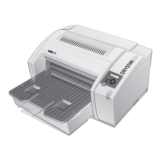
Page 18: The User Interface
Overview of user interface controls Power/Reset button Display Keypad Status indicator LED Film input tray Film output tray Never try to open the printer when the Drystar 5300 is printing a film. Always follow the instructions on the display! 2920B EN 20031206... - Page 19 • To reset the printer. Do NOT press the Power/Reset button without first following the procedure to stop printing when the Drystar 5300 is printing a film. Refer ‘Switching off the Drystar 5300’ on page 30. 2920B EN 20031206...
- Page 20 Rear panel At the rear side of the printer, one slot and three connectors are available: • To insert an external CF-card for software CF-card slot installation, backup, etc. Network • To connect a remote PC (used for access via the connector web browser pages).
- Page 21 Inserting a CF-card To insert a CF-card in the Drystar 5300 (the slot is located at the rear side): Hold the CF-card vertically with the connector holes in front of the slot, and with the flat surface pointing to the left.
- Page 22 Removing a CF-card To remove a CF-card from the Drystar 5300 slot: Push the unlocking lever underneath the CF-card slot. The CF-card is pushed slightly outward. Remove the CF-card gently from the slot. 2920B EN 20031206...
- Page 23 The Drystar 5300 gives status information via beeps. The length of the beep indicates the response of the system to a key command. • A short beep means that Drystar 5300 has accepted the key command and is starting the operation. •...
- Page 24 (In key-operator mode) Confirm key • To select a menu. • To accept an entry in a menu. • To move the cursor to the previous entry field. • To scroll upwards. Up key • To increment the number in a(n) (alpha)numerical entry field.
- Page 25 The display The Drystar 5300 control panel has a backlit LCD display with 4 lines of 20 characters each (2 lines of 7 characters for Greek or Asian languages). Its lay-out depends on the operating mode. General display features The figure below shows how the display is illustrated in this manual:...
- Page 26 In operator mode, appropriate information is displayed in accordance with the status of the printer. The operator basic screen looks as follows, indicating that the Drystar 5300 is ready for operation and that no job is currently being executed. READY...
- Page 27 To accept an entry in a menu, press the Confirm key. • A short beep acknowledges and terminates the entry. • The Drystar 5300 will sound a long beep if you press a key that is not to be used at that moment. 2920B EN 20031206...
-
Page 28: Switching On The Drystar 5300
LED is constantly green. READY " It takes 13 minutes (starting up of the Drystar 5300 and heating up of the thermal print head) before you can start printing. The display will inform you that the printer is warming up:... - Page 29 • If, on the front panel display, the print queue screen is shown, the status indicator LED is green and blinking. Modaname 10:21:34 PR film 1 of 6 Modaname 10:21:34 CA xx Jobs in memory WA Make sure that the printer is loaded with appropriate consumables. "...
-
Page 30: Switching Off The Drystar 5300
Make sure that pending jobs are correctly finished. If necessary, follow the procedure to stop printing. Press the Power/Reset button to switch off the Drystar 5300. • If the printer is ready, it shuts down immediately: Power off initiated Please wait •... -
Page 31: Chapter 2: Basic Operation (Operator Mode)
Basic operation (Operator mode) This chapter will inform on how to manage the print queue, how to print films with priority and how to load new films. Overview of operator functions Managing the print queue About Drystar 5300 consumables Loading films... -
Page 32: Overview Of Operator Functions
Overview of operator functions This section focuses on the basic operating principles of the Drystar 5300. After reading this chapter, the operator should be able to produce diagnostic usable hardcopies. No special technical skills are required. All basic operator functions can be activated directly by pressing a single key on the keypad. -
Page 33: Managing The Print Queue
Checking the print queue If jobs have been transmitted from the network to the Drystar 5300, they are put in the print queue on a first in, first out schedule. New jobs that are added to the queue get the ‘waiting’ status. - Page 34 A description of the possible status of the jobs is listed in the table below: Status Description Printing Printing of this job is in progress. The necessary calculations are already being Calculating made before printing of the job can be started. Waiting Jobs are queued in the printer memory.
-
Page 35: About Drystar 5300 Consumables
About Drystar 5300 consumables The Drystar 5300 can handle blue-transparent and clear-transparent films. Available film formats are 11x14” and 14x17”. When a new film pack is loaded, the Film Identification tag is read and the printer settings are automatically adjusted. -
Page 36: Loading Films
" The Drystar 5300 can be loaded with new films in full daylight. Loading films is easy and can be done very quickly. Follow the procedures as described in this section. The Drystar 5300 will inform you in several ways when a film tray is empty: • an audible signal, •... - Page 37 Wait while the printer finishes printing any current jobs. When the film path is cleared, proceed with step 3. When the Drystar 5300 is in the ready state and the input tray is empty: The display shows the following message:...
- Page 38 The printer is ready to receive a new film when the following message appears: - Remove cover sheet from tray - Load new film - Close tray Remove the white (protective) film sheet. Take film pack and slide it into the input tray. "...
- Page 39 Either remove the sticker completely, or leave it on the film bag; DO NOT leave it on the triangular flap! Slide the film pack completely into the input tray. 2920B EN 20031206...
- Page 40 Tear the plastic tape from around the film pack. Close the input tray. " The Drystar 5300 resumes printing as soon as the tray is closed. " Loading instructions are also available inside the input tray cover. 2920B EN 20031206...
- Page 41 Loading a single film in the input tray " When you load a single film sheet (e.g. after removing it from the input tray, or after film jam), make sure that it is correctly positioned. Refer to ‘Checking the correct position of a film in the input tray’ on page 42.
- Page 42 Checking the correct position of a film in the input tray " You can verify that the film is properly loaded by watching the lower right corner of the films in the input tray. The rounding of this corner should be smaller than the other three corners.
-
Page 43: Chapter 3: Advanced Operation (Key-Operator Mode)
Chapter Advanced operation (Key-operator mode) This chapter gives an overview of functions for the advanced user: Overview of key-operator functions Viewing printer information Changing the configuration settings Printing images Saving the configuration settings Restoring the configuration settings Maintaining optimal image quality Service actions Quality control procedure Installation operations... -
Page 44: Overview Of Key-Operator Functions
The key-operator menus make it possible to use the Drystar 5300 advanced functions. If not specified otherwise, the functions are described in detail in this chapter. For general information on the key functions of the Drystar 5300, refer to ‘The user interface’... -
Page 45: The Menu Structure
The menu structure General Show settings General Default densitometer Input tray Per modality setting Network(DICOM) Etc... Image quality Installed data-sets Time and date Language Beep on empty tray General Change settings Film view Input tray Film type Network(DICOM) Film format Image quality Test image Print image... - Page 46 5 Restore config. 6 Calibration 7 Service actions 8 Quality Control 9 Installation " When you enter the key-operator mode while the Drystar 5300 is printing, it will first finish the active print job(s): Stopping printing process before entering key-op mode Please wait.
- Page 47 Press the Confirm key to return to the key-operator menu. Otherwise, the key- operator menu will be closed. " The Drystar 5300 will sound a long beep if you press a key that is not to be used at that moment.
-
Page 48: Viewing Printer Information
Viewing printer information A number of data and parameter settings of the printer can be viewed by using the ‘Show settings’ function: Show settings Page General ‘Viewing general information’ Input tray ‘Viewing input tray information’ Network (DICOM) ‘Viewing network (DICOM) information’ Image quality ‘Viewing general image quality information’... - Page 49 Accessing the Show settings menu Press the Key-operator key to enter the key-operator mode. On the key-operator main menu, press the Confirm key to select ‘Show settings’. The Show settings menu is displayed: 1 General 2 Input tray 3 Network (DICOM) 4 Image quality 5 Installed data-sets 6 Logical printers...
-
Page 50: Viewing General Information
" More information, such as site specific data can be viewed via the browser only. Refer to Chapter 4, ‘Controlling the Drystar 5300 via a remote PC (with browser)’. Press the Confirm key to return to the Show settings menu. -
Page 51: Viewing Input Tray Information
Viewing input tray information Perform steps 1 and 2 of the ‘Accessing the Show settings menu’ procedure, on page 49. On the Show settings menu, press the Down key, followed by the Confirm key to select ‘Input tray’. The ‘Input tray’ screen is displayed (example): Status: OK Tag info: Film type: DT 2B... -
Page 52: Viewing Network (Dicom) Information
IP address of the Service Host PC, • the MAC address of the Drystar 5300, • whether the Drystar 5300 sends an e-mail when an error occurs (ON, OFF). Press the Confirm key to return to the Show settings menu. 2920B EN 20031206... -
Page 53: Viewing General Image Quality Information
Viewing general image quality information Perform steps 1 and 2 of the ‘Accessing the Show settings menu’ procedure, on page 49. On the Show settings menu, press the Down key three times, followed by the Confirm key to select ‘Image quality’. The following screen will appear: 1 General 2 Def. -
Page 54: Viewing Default Densitometer Information
The name of the default densitometer is displayed: Default densitometer: MacBeth TR924 " All densities shown on the Drystar 5300 display are calculated according to the response of the selected densitometer. Refer to ‘Density response of Drystar media’ on page 106. -
Page 55: Viewing Image Quality Information Of A Modality
Viewing image quality information of a modality Perform steps 1 and 2 of the ‘Accessing the Show settings menu’ procedure, on page 49. On the Show settings menu, press the Down key three times, followed by the Confirm key to select ‘Image quality’. The following screen will appear: 1 General 2 Def. -
Page 56: Viewing Installed Data-Sets Information
Viewing installed data-sets information Perform steps 1 and 2 of the ‘Accessing the Show settings menu’ procedure, on page 49. On the Show settings menu, press the Down key four times, followed by the Confirm key to select ‘Installed data-sets’. The ‘Installed data-sets’... -
Page 57: Viewing Logical Printers Information
Viewing logical printers information Perform steps 1 and 2 of the ‘Accessing the Show settings menu’ procedure, on page 49. On the Show settings menu, press the Down key five times, followed by the Confirm key to select ‘Logical printers’. The ‘Logical printers’... -
Page 58: Changing The Configuration Settings
Changing the configuration settings A number of data and parameters settings of the printer can be viewed and changed by using the ‘change settings’ function: " Each time the settings have been changed, the new configuration is automatically saved on the internal CF-card of the printer. You will be asked to create a backup CF-card with the new settings. - Page 59 2 Input tray 3 Network (DICOM) 4 Image quality " This menu is the starting point for changing the Drystar 5300 settings (see below). Press the Escape key to return to the key-operator main menu. Press the Escape key to quit the key-operator mode.
- Page 60 Each time the settings have been changed and confirmed, an automatic backup of the old configuration is made on the internal CF-card. You will also be asked to create a backup on an external CF-card. After selecting YES, the ‘Update backup on CF-card’ screen is displayed: Update backup on CF-card YES (v)
-
Page 61: Changing The Date And Time
Changing the general settings Changing the date and time Perform steps 1 to 2 of the ‘Accessing the Change settings menu’ procedure on page 59. On the ‘Change settings’ screen, press the Confirm key to select ‘General’. The ‘General’ screen is displayed: 1 Date &... -
Page 62: Changing The Language
On the ‘General’ screen, press the Down key, followed by the Confirm key to select ‘Language’. The ‘Language’ screen is displayed with the available languages (only the Western languages are shown in this manual; contact Agfa for the latest Drystar 5300 language availability status): 1* English 2 Français... -
Page 63: Changing The Beep On Empty Tray Settings
Changing the beep on empty tray settings You can change the way the Drystar 5300 warns the user of an empty input tray situation. Perform steps 1 to 2 of the ‘Accessing the Change settings menu’ procedure on page to select the ‘General’ screen. -
Page 64: Changing The Site Specific Data (Via Remote Browser Only)
Changing the site specific data (via remote browser only) The following site specific data are stored in the Drystar 5300 memory: Field Mandatory Site name Site address (contact) City Tel. country code Tel. number Modem Department Contact person Delivery address E-mail address Modem tel. -
Page 65: Changing The Film View
Changing the input tray settings Changing the film view Using the following procedure you can change the film view. Perform steps 1 and 2 of the ‘Accessing the Change settings menu’ procedure on page 59. On the Change settings menu, press the Down key, followed by the Confirm key to select ‘Input tray’. -
Page 66: Changing The Film Type
Changing the film type Using the following procedure you can overrule the film type which is automatically read by means of the Film Identification tag on the film pack. This procedure is only to be used exceptionally when the Film Identification tag info is incorrect. -
Page 67: Changing The Film Format
Changing the film format Using the following procedure you can overrule the film format which is automatically read by means of the Film Identification tag on the film pack. This procedure is only to be used exceptionally when the Film Identification tag info is incorrect. - Page 68 " If the format is changed from the previous format, the following message appears (example): Please modify input tray for 11x14” You must modify the tray configuration. Refer to ‘Changing the film format of the trays’ on page for more information. Press the Confirm key to continue.
-
Page 69: Changing The Printer Ae_Title
Changing network (DICOM) configuration Changing the printer AE_Title Perform steps 1 to 2 of the ‘Accessing the Change settings menu’ procedure on page 59. On the Change settings menu, press the Down key twice, followed by the Confirm key to select ‘Network (DICOM)’. The ‘Network (DICOM)’... -
Page 70: Changing The Hostname
Changing the hostname Perform steps 1 to 2 of the ‘Accessing the Change settings menu’ procedure on page 59. On the Change settings menu, press the Down key twice, followed by the Confirm key to select ‘Network (DICOM)’. The ‘Network (DICOM)’ screen is displayed: 1 Printer AE_Title 2 Hostname 3 Domain name... -
Page 71: Changing The Domain Name
Changing the domain name Perform steps 1 to 2 of the ‘Accessing the Change settings menu’ procedure on page 59. On the Change settings menu, press the Down key twice, followed by the Confirm key to select ‘Network (DICOM)’. The ‘Network (DICOM)’ screen is displayed: 1 Printer AE_Title 2 Hostname 3 Domain name... -
Page 72: Changing The Printer Ip Address
Changing the printer IP address Perform steps 1 to 2 of the ‘Accessing the Change settings menu’ procedure on page 59. On the Change settings menu, press the Down key twice, followed by the Confirm key to select ‘Network (DICOM)’. The ‘Network (DICOM)’... - Page 73 Example 1: if the IP address is 123.001.123.123, then the data entry should be as follows: Printer IP addr.: 123.001.123.123 (255.255.255.255) Example 2: if the IP address is 123.1.123.123, then the data entry should be as follows: Printer IP addr.: 123.
-
Page 74: Changing The Service Host Ip Address
Changing the service host IP address Perform steps 1 to 2 of the ‘Accessing the Change settings menu’ procedure on page 59. On the Change settings menu, press the Down key twice, followed by the Confirm key to select ‘Network (DICOM)’. The ‘Network (DICOM)’... - Page 75 Example 1: if the IP address is 123.001.123.123, then the data entry should be as follows: Serv.Host IP add: 123.001.123.123 (255.255.255.255) Example 2: if the IP address is 123.1.123.123, then the data entry should be as follows: Serv.Host IP add: 123.
-
Page 76: Changing The Netmask
Changing the netmask Perform steps 1 to 2 of the ‘Accessing the Change settings menu’ procedure on page 59. On the Change settings menu, press the Down key twice, followed by the Confirm key to select ‘Network (DICOM)’. The ‘Network (DICOM)’ screen is displayed: 1 Printer AE_Title 2 Hostname 3 Domain name... -
Page 77: Changing The Router Ip Address
Changing the router IP address Perform steps 1 to 2 of the ‘Accessing the Change settings menu’ procedure on page 59. On the Change settings menu, press the Down key twice, followed by the Confirm key to select ‘Network (DICOM)’. The ‘Network (DICOM)’... - Page 78 Example 1: if the IP address is 123.001.123.123, then the data entry should be as follows: Router IP address: 123.001.123.123 (255.255.255.255) Example 2: if the IP address is 123.1.123.123, then the data entry should be as follows: Router IP address: 123.
-
Page 79: Removing A Modality
Removing a modality Perform steps 1 to 2 of the ‘Accessing the Change settings menu’ procedure on page 59. On the Change settings menu, press the Down key twice, followed by the Confirm key to select ‘Network (DICOM)’. The ‘Network (DICOM)’ screen is displayed: 1 Printer AE_Title 2 Hostname 3 Domain name... -
Page 80: Adding A Modality
Adding a modality Perform steps 1 to 2 of the ‘Accessing the Change settings menu’ procedure on page 59. On the Change settings menu, press the Down key twice, followed by the Confirm key to select ‘Network (DICOM)’. The ‘Network (DICOM)’ screen is displayed: 1 Printer AE_Title 2 Hostname 3 Domain name... - Page 81 Press the Confirm key to store the data, or the Escape key to quit the procedure without any changes. The ‘Select modality brand name’ screen is displayed: Select modality brand name: 1 Agfa 2 CR entry 3 Fuji 4 Trixell 5 Lumisys 6 Other Press the up/down arrow keys to select the appropriate modality brand name.
- Page 82 The ‘select modality AE_Title’ screen is displayed: Select modality AE_Title: 1 Enter via keypad 2 Modality16char 3 Etc... Press the up/down arrow keys to select the appropriate modality AE_Title. $ If you have selected ‘1 Enter via keypad’, the ‘Enter modality AE_Title’ screen is displayed: Enter modality AE_Title:...
- Page 83 The printer will ask you if you want to add another modality: Add other modality? YES (v) NO (x) If you wish to add another modality, press the Confirm key (YES). You will be taken back to step to repeat the procedure. If you do not wish to add another modality, press the Escape key (NO).
-
Page 84: Setting The Alert Mailing
* OFF The currently active state is indicated with a ‘*’: Using the arrow keys, select YES to enable the Drystar 5300 to send an automatic e-mail in case of a problem, or NO to quit the procedure without any changes. - Page 85 " For more information on film calibration settings: refer to ‘Understanding the calibration policy’ on page 102. Press the up/down key to select the film calibration default. When the setting is ON, the Drystar 5300 will ask you to enter the calibration frequency: Select Frequency Every film packs Enter the calibration frequency by means of the up/down key.
- Page 86 The current default densitometer is indicated with a ‘*’. Press the up/down key to select the default densitometer. " All densities that are shown on the Drystar 5300 screens are according to the response of the default densitometer. Refer also to ‘Density response...
- Page 87 2 Select other " If you want to use these profile default settings for the current modality, press the Confirm key. The Drystar 5300 will be loaded with these settings and return to the ‘Image quality’ main menu. 2920B EN 20031206...
- Page 88 " If you do not want to use the default settings, press the Down key, followed by the Confirm key to choose ‘Select other’. The Drystar 5300 will continue with the ‘Select for Modality’ screen, allowing you to change the Look-up table, the Interpolation and the MaxD values manually, as explained in the following paragraphs.
- Page 89 Changing the interpolation Perform steps 1 to 3 of the ‘Changing Image quality settings for a modality’ procedure on page to select the modality and choose ‘Select other’. The ‘Select for Modality’ screen is displayed: Select for Modality16char: 1 Look-up table 2 Interpolation 3 MaxD In the ‘Select for Modality’...
- Page 90 $ If you select “CubicBell”, the following screen will appear, allowing you to adjust the smoothing factor: Enter smoothing parameter: advised value = 0.35 range [0.1-10] enter absolute value y.yy Enter the smoothing factor value by means of the arrow keys. Refer to ‘Data entry’...
-
Page 91: Printing Images
Printing images A number of ‘test’ images can be printed, either from an external CF-card or from the internal CF-card: Show settings Page Test image ‘Printing test images’ From CF-card ‘Printing files from an external CF-card’ Accessing the print images menu Press the Key-operator key to enter the key-operator mode. - Page 92 Printing test images Test images are useful for checking the print quality. The Drystar 5300 offers a number of built-in test images stored on the internal CF-card. Perform steps 1 to 2 of the ‘Accessing the print images menu’ procedure on page to select the ‘Print image’...
- Page 93 Printing files from an external CF-card TIFF images stored on an external CF-card can be printed using the ‘Print from CF-card’ function. " No compressed TIFF-files are allowed. Perform steps 1 to 2 of the ‘Accessing the print images menu’ procedure on page to select the ‘Print image’...
- Page 94 The ‘Queuing file’ screen will be shown to indicate to the operator that the printing action is accepted and in process: Queuing file < filename> Please wait After about five seconds this screen will disappear. " If the printer memory is full, the following message will appear: Unable to accept new job while printing...
-
Page 95: Saving The Configuration Settings
Saving the configuration settings Each time the settings have been changed and confirmed, an automatic backup of the old configuration is made on the internal CF-card. You will also be asked to create a backup on an external CF-card. It is also possible (and recommended) to regularly make a backup of the printer settings to ensure safe restoring of the values when required. - Page 96 In both cases, the printer will ask you to insert a CF-card: Save Configuration Please insert card Insert a CF card. " Refer to ‘Inserting a CF-card’ on page 21. If there are already save set files present on the CF-card, a list is shown. The ‘Select dataset’...
-
Page 97: Restoring The Configuration Settings
Restoring the configuration settings When necessary, you can restore the configuration settings of the printer. The following functions are available for restoring a backup copy of the configuration files: • ‘Restoring printer settings from an external CF-card’ (page 98) • ‘Restoring the previous configuration from the internal CF-card’... - Page 98 Restoring printer settings from an external CF-card Perform steps 1 to 3 of the ‘Accessing the restore configuration menu’ procedure on page to select the ‘Restore from CF-card’ screen. Press the Confirm key to select ‘External’. The ‘Restore configuration’ screen is displayed: Restore configuration 1 General...
- Page 99 Press the up/down arrow keys to select the desired save set file, followed by the Confirm key. The following confirmation screen is displayed: Restore from CF-card <Dataset def v1.00> YES (v) NO (x) Press the Confirm key (YES) to proceed with the selected file, or the Escape key (NO) to quit the procedure without any changes.
- Page 100 Restoring the previous configuration from the internal CF-card Perform steps 1 to 3 of the ‘Accessing the restore configuration menu’ procedure on page to select the ‘Restore from CF-card’ screen. Press Down key, followed by the Confirm key to select ‘Internal’. The following confirmation screen is displayed: Restore from CF-card...
-
Page 101: Maintaining Optimal Image Quality
• Before initial use of a film, • After a certain number of copies have been printed. Overview of calibration functions One calibration function is provided for the Drystar 5300. Calibration Purpose When? • To measure and set the system density of the •... - Page 102 Understanding the calibration policy Manual or automatic film calibration You should regularly perform a film calibration to assure that the image quality is still optimal. Film calibration can be initiated in 2 ways: • Automatically, i.e. after loading a new film pack (frequency is adjustable), •...
- Page 103 Accessing the Calibration menu Press the Key-operator key to enter the key-operator mode. On the key-operator main menu, press the Down key five times followed by the Confirm key to select ‘Calibration’. The ‘Calibration’ menu is displayed: 1 Film calibration 2 Therm.
- Page 104 MDM (Macro Densitometer). The Drystar 5300 is being calibrated during the printing process. " If the Drystar 5300 cannot read the Film identification tag, a calibration is impossible and the following message is displayed: Unidentified media...
- Page 105 When the film calibration has been completed successfully, three cases are possible: • Calibration successful, results OK. The obtained MaxD (3.10) after calibration, is displayed: Flashing Film Flashing calibration OK MaxD = 3.10 (xxxxx) (xxxxx) is the code of the Densitometer type (refer to ‘Changing the default densitometer’...
- Page 106 Check the printed test film. The test film should be similar to the image below. FilmCalib53_14x17.BMP (Version2) The calibration film must be free of dust particles or any other artifacts. If this is not the case, clean the print head (refer to ‘Print head cleaning’...
- Page 107 Print head cleaning Print head cleaning must be done when image quality problems occur. To clean the print head: Perform steps 1 to 2 of the ‘Accessing the Calibration menu’ procedure on page to select the ‘Calibration’ screen. On the Print image menu, press the Down key, followed by the Confirm key to select ‘TPH cleaning’.
-
Page 108: Service Actions
Service actions The Drystar 5300 has the capability of assisting the Service engineer to maintain or repair the printer. Overview of service actions Four groups of service actions are provided by the Drystar 5300. Action Purpose Who? • Customer (hospital •... -
Page 109: Quality Control Procedure
In order to establish and maintain constant image quality, a regular evaluation of the image quality is advised. The Drystar 5300 Imager contains an automatic QC feature designed to maintain optimum image quality. The QC procedure consists of two main steps: •... - Page 110 Establishing the reference values and verifying image quality After installation of a new Drystar 5300 Imager and before initial use you must establish Quality Control aim values. These values will be used as the base line for comparison when daily Quality Control is done. These values should be determined again after major service or repair.
- Page 111 Base+Fog density, • Mid density, • DD (Density Difference), • MaxD (maximum density). By default, the internal densitometer of the Drystar 5300 will be used. The internal densitometer of the Drystar 5300 is calibrated at installation. Authorized service personnel should recalibrate internal densitometer annually or after major service or repair.
- Page 112 After the image is printed, the Drystar 5300 will display the optical density values: QC readings: Base+Fog x.xx Mid Density x.xx DD x.xx MaxD x.xx (densitometer=xxxxx) The displayed values represent the following steps on the test film: • Base+Fog -The density value of the Base + Fog step.
- Page 113 " The calculated ‘Operating levels’ should respect the following tolerances: Operating level Tolerance Base + Fog - 0.03 / + 0.05 Mid density +/- 0.20 DD (Density difference) +/- 0.20 MaxD +/- 0.25 " The tolerances may be different according to local regulations. These charts will be used for the daily quality test.
- Page 114 Print the 'QC ' test image or use the previously printed QC test image used to establish the daily operating density levels. You should obtain an image looking like this: Initials : _____ Date : __________ Drystar 5300 Quality Control Test Image Geometry Test Sharpness Test Density test Base + Fog:...
- Page 115 (use a magnifying glass and optimize viewing conditions). Record these values at the top of the Drystar 5300 Chart 3 (‘Drystar 5300 Artifacts and Spatial Resolution Control Chart’). Refer to Appendix C ‘Quality...
- Page 116 To establish the image geometry reference values, proceed as follows: Print the 'QC ' test image or use the previously printed QC test image. You should obtain an image looking like this: Drystar 5300 Quality Control Test Image Initials : _____ Date : __________...
- Page 117 0.5 mm divisions (1/64 inch). Record these values as reference dimensions A and B on the Drystar 5300 Chart 4 (‘Drystar 5300 Geometric Consistency Control Chart’). Refer to Appendix C ‘Quality Control Charts’ on page 199. These charts will be used for the annual quality test. For more information, refer to ‘Performing the annual QC test (Geometric Consistency Test)’...
- Page 118 Performing the daily QC test This test must be performed every day before any clinical film can be processed. Switch on the Drystar 5300 and wait for at least 15 minutes. Refer to ‘Switching on the Drystar 5300’ on page 28.
- Page 119 (NO) to quit. QC procedure in progress Please wait The Drystar 5300 will automatically print the QC test image. After the QC test image is printed, the Drystar 5300 will display the optical density values: QC readings: Base+Fog x.xx Mid Density x.xx DD x.xx MaxD x.xx...
- Page 120 3 groups, each having 5 dots. All five dots of each group must be visible (use a magnifying glass and optimize viewing conditions). Record the results on Drystar 5300 Chart 3 (Drystar 5300 ‘Artifacts and Spatial Resolution Control Chart’). Refer to Appendix C ‘Quality Control...
- Page 121 We strongly recommend using a 30-cm (12-inch) machinist scale with 0.5 mm divisions (1/64 inch). Record these values as measured dimensions A and B on the Drystar 5300 Chart 4 (‘Drystar 5300 Geometric Consistency Control Chart’). Refer to Appendix C ‘Quality Control Charts’...
-
Page 122: Installation Operations
Installation operations Two installation operations are possible: • install new software, or upgrade existing software on the internal CF-card: • ‘Software installation from an external CF-card’ (page 123), • ‘Software installation from the previous version on the internal CF-card’ (page 125), •... - Page 123 " Before the procedure starts, the system suggests you make a backup copy of the current configuration. It is highly recommended to do this, so you can always restore it in case something should go wrong. The following screen is displayed: Before install please make backup 1 OK, make backup...
- Page 124 The ‘Select dataset’ screen is displayed: Select dataset Dataset xyz v1.00 Dataset abc v1.00 Dataset def v1.00 etc... Press the up/down arrow keys to select the desired save set file, followed by the Confirm key. The following confirmation screen is displayed: Installation from CF-card <Dataset def v1.00>...
- Page 125 Software installation from the previous version on the internal CF-card This is the continuation from step on page Press the down key once, followed by the Confirm key to select ‘Previous SW version’. The printer restores the previous SW configuration from the internal CF-card: Copying C:/<path><filename>...
- Page 126 Using the installation wizard When you install the Drystar 5300, the installation wizard will guide you through the complete installation procedure. The installation wizard consists of three steps: • ‘Entering the printer network settings’ (page 129), • ‘Entering modality specific settings’...
- Page 127 The ‘Language’ screen is displayed with the available languages (only the Western languages are shown in this manual, contact Agfa for the latest Drystar 5300 language availability status): 1* English 2 Français 3 Deutsch 4 Nederlands 5 Dansk 6 Suomi...
- Page 128 Automatic Manual • When you select ‘Automatic’, the Drystar 5300 will try to initialize all parameters automatically and use them as default values in the following screens. This can save much time. • When you select ‘Manual’, you will have to enter all values manually, unless factory settings are available.
- Page 129 Entering the printer network settings Some instruction screens will show the information you need to complete this part of the installation: Installation wizard Step 1: Printer Network settings Press the Confirm key to continue. Information concerning: -Printer IP-address -Service Host IP-addr -Netmask in case of subnets -Router IP address...
- Page 130 Example 2: if the IP address is 123.1.123.123, then the data entry should be as follows: Printer IP addr.: 123. 1.123.123 (255.255.255.255) Press the Confirm key to store the data, or the Escape key to quit the procedure without any changes. The ‘Service Host IP address’...
- Page 131 The ‘Netmask’ screen is displayed: Netmask 255.255.255. (255.255.255.255) If the netmask has already been assigned, it will be shown on the display. Enter the netmask by means of the arrow keys. Refer to ‘Data entry’ page 27. " Note that blank spaces will be ignored (see example). Example: if the netmask is 255.255.255.0, then the data entry should be as follows: Netmask 255.255.255.
- Page 132 Press the Confirm key to store the data, or the Escape key to quit the procedure without any changes. The ‘Printer AE_Title’ screen is displayed: Printer AE_Title: [Drystar (max. 16 char) If the Printer AE_Title has already been assigned, it will be shown on the display. Change the Printer AE_Title by means of the arrow keys.
- Page 133 Press the Escape key to exit the wizard on the local keypad. Refer to ‘Controlling the Drystar 5300 via a remote PC (with browser)’ on page 139. If you wish to continue with the installation wizard from the local keypad, press the Confirm key to continue.
- Page 134 Press the Confirm key to store the data, or the Escape key to quit the procedure without any changes. The ‘Select modality brand name’ screen is displayed: Select modality brand name: 1 Agfa 2 CR entry 3 Fuji 4 Trixell 5 Lumisys 6 Other Press the up/down arrow keys to select the appropriate modality brand name.
- Page 135 $ If you have selected ‘1 Enter via keypad’, the ‘Enter modality AE_Title’ screen is displayed: Enter modality AE_Title: [Name_____ __] (max. 16 char) Enter the modality AE_Title by means of the arrow keys. Refer to ‘Data entry’ page 27. Make sure not to enter more than 16 characters. Press the Confirm key to store the data, or the Escape key to quit the procedure without any changes.
- Page 136 A screen summarizing the information you have entered will appear: Following data is entered: Daily used name: CTscanner Brand: Philips Modality-type: EasyVision Modality AE_Title: AE 0123456 Preferred film type: Drystar DT 2B -------------------------- x Repeat step 2 v OK The data entry for the new modality is finished now. Press the Confirm key to continue the installation wizard or press the Escape key to repeat step 2.
-
Page 137: Saving The Configuration
Saving the configuration You need to complete this step, otherwise all the install data you have entered will be lost! A screen will ask you to insert the backup CF-card: Save configuration Pls. Insert CF-card Insert the CF-card. " Refer to ‘Inserting a CF-card’... - Page 138 The installation is now finished, and the following screen is displayed: Installation finished. Please use menu: Change settings and Calibration For further actions Press the Confirm key to accept the installation or press the Escape key to redo the installation. 2920B EN 20031206...
-
Page 139: Chapter 4: Controlling The Drystar 5300 Via A Remote Pc (With Browser)
Controlling the Drystar 5300 via a remote PC (with browser) This chapter will inform you on how to control the functions of the Drystar 5300 via the browser on a remote PC. Features Set up Setting up the connection Starting the remote session... -
Page 140: Features
A network adapter, • A cross-link Ethernet cable (for a direct link between PC and Drystar 5300) or a straight Ethernet cable (for a connection via an existing network). Using the remote PC, you have access to four operating modes of the Drystar 5300: Key-operator mode, Service mode, Specialist mode, and Administrator (Security). -
Page 141: Set Up
Set up The Drystar 5300 and the PC with browser can be set up in two ways: • using a crossed network cable, or • using a straight network cable. Configuration with crossed network cable In this configuration, a crossed network UTP cable is used to connect the service PC directly to the printer. -
Page 142: Setting Up The Connection
Setting up the connection Setting up a direct link (configuration with crossed network cable) To set up a direct link, you have to follow two procedures: • Attribute a fixed IP address to the PC, • Switch off all proxy setting in the browser. When setting up a link, bare in mind the following important hints: •... - Page 143 In the Control Panel menu, double-click Network. In the Network window, select TCP/IP Protocol, select the Protocols tab, and click Properties. 2920B EN 20031206...
- Page 144 Specify IP address and subnet mask and click OK. Switching off the proxy settings of the browser Open the browser. In the Tools menu, click Internet Options. The Internet Options window will appear. 2920B EN 20031206...
- Page 145 In the Internet Options window, go to the Connections tab and click LAN Settings. The Local Area Network (LAN) Settings window will appear. Switch off all proxy settings of the browser and click OK. The PC is ready to make a connection. Refer to ‘Starting the remote session’...
- Page 146 Setting up a link through a network (configuration with straight network cable) Attribute a fixed and available IP address to your PC. Refer to ‘Attributing a fixed IP address to the PC’ on page 142. The PC is ready to make a connection. Refer to ‘Starting the remote session’...
-
Page 147: Starting The Remote Session
Starting the remote session Starting the remote session To start the remote session, enter the Drystar 5300 IP address in the Address bar of the browser. The Browser welcome page appears: There are four access levels: Key-operator, Service Engineer, Specialist and Security. - Page 148 • Password: 5300 You now have access to the Drystar 5300 functions in the key-operator mode. " Only one session is active at one time on one printer. " A remote session disables the local keypad and display. While you work...
-
Page 149: Chapter 5: System Description
Chapter System description In this informative chapter you will find mechanical and functional descriptions. Main components Functional description Changing the film format of the trays Drystar 5300 network configuration Transport after installation... -
Page 150: Main Components
Main components Front view Top cover Output tray User interface (refer to page 18) Input tray Rear view CF-card slot Network connector Input/output connector Power connection 2920B EN 20031206... -
Page 151: Functional Description
Functional description The Drystar 5300 consists of two functional blocks: a controller and a print engine. The controller • captures the incoming digital data and stores the image on a CF-card, • composes the different images, and • generates the appropriate print engine control signals. -
Page 152: Changing The Film Format Of The Trays
‘film format’ parameter is automatically read from the Film Identification tag when the new film pack is loaded. " By default, the Drystar 5300 is configured for 14x17”. The paragraphs below describe the procedure to change the configuration to 11x14”. The procedure for changing the configuration from 11x14”... - Page 153 Place the Drystar 5300 with its input tray over the edge of the table, to facilitate access to the bottom of the tray, as illustrated below: Take a cross head screwdriver and remove the 3 screws underneath the input tray, as illustrated below:...
- Page 154 Lower the film positioner unit. Remove the film positioner cable out of its retainers. 2920B EN 20031206...
- Page 155 Push the film positioner cable into the Drystar 5300 housing. Put and hold the film positioner into its new place. 2920B EN 20031206...
- Page 156 Using the cross head screwdriver, remount the 3 screws to fix the film position unit. 2920B EN 20031206...
-
Page 157: Drystar 5300 Network Configuration
Drystar 5300 network configuration The Drystar 5300 is a standard network printer. This means that you can just plug it into the (existing) ethernet network without any additional options or accessories. Drystar 5300 is also a native DICOM printer. Therefore the... - Page 158 Modality Paxport Drystar 5300 Example of Drystar 5300 in a point-to-point configuration * Paxport is required if the modality is not a DICOM modality. 2920B EN 20031206...
-
Page 159: Transport After Installation
Transport after installation The Drystar 5300 is quite compact, so moving the printer over a short distance - if required - can be done in a convenient way. " Refer to ‘Safety precautions’ on page 8. Always keep in mind the following safety guidelines: •... - Page 160 2920B EN 20031206...
-
Page 161: Chapter 6: Preventive Maintenance
Chapter Preventive maintenance This chapter guides the user through maintenance and cleaning tasks which require no special skills, tools nor training: Preventive maintenance schedule Cleaning the exterior Cleaning the print head resistor line... -
Page 162: Preventive Maintenance Schedule
Do not touch the resistor line of the print head. • Always switch off the Drystar 5300 and disconnect the power cord from the outlet before carrying out any maintenance work inside the printer. " Film jam removal or cleaning the printer head can be done without switching the power off. -
Page 163: Cleaning The Exterior
Cleaning the exterior Switch off the Drystar 5300 by following the procedure as described in ‘Switching off the Drystar 5300’ on page 30. Remove the power plug from the socket. Wipe the exterior of the printer with a clean, soft, damp cloth. -
Page 164: Cleaning The Print Head Resistor Line
Cleaning the print head resistor line Print head cleaning must be done when image quality problems occur. For more information on maintaining image quality, refer to ‘Image quality problems’ on page 186. To clean the print head: Press the Key-operator key to enter the key-operator mode. On the key-operator main menu, press the Down key five times, followed by the Confirm key to select ‘Calibration’. - Page 165 Open the top cover. As soon as the top cover is opened, the ‘Thermal head cleaning’ screen continues giving the following instructions: THERMAL HEAD CLEANING - Clean thermal head - Close top cover Open the hold-down bracket. 2920B EN 20031206...
- Page 166 Open the print head unit. The print head unit can be warm. Locate and check on sight the print head resistor line. " Be careful not to touch the print head resistor line with your fingers. 2920B EN 20031206...
- Page 167 Clean the print head resistor line. Gently pass over the resistor line a few times with a lint free cloth, slightly moistened with Isopropyl alcohol or Ethanol. Do this only in one direction, i.e. from left to right, without lifting the cloth. "...
- Page 168 2920B EN 20031206...
-
Page 169: Chapter 7: Troubleshooting
Chapter Troubleshooting This chapter serves as a guide to identify and solve possi- ble problems you may encounter. Troubleshooting checklists The Drystar 5300 does not print Clearing of film jams Film identification problems Startup errors Image quality problems Warning messages... -
Page 170: Troubleshooting Checklists
Troubleshooting checklists General problems The table below lists some general problems which can occur when working with the Drystar 5300. • The Drystar 5300 does not print. Action Refer to Page ‘Checking the status indicator LED’ Check the Drystar 5300 ‘Checking the connections’... - Page 171 Checking the status indicator LED The LED on the front panel indicates the Drystar 5300 operating status. Use the following table to determine the status of your printer. Receive Printing Color Light Status Action jobs? Ready (standby) Proceed. Constant Startup sequence...
-
Page 172: The Drystar 5300 Does Not Print
The Drystar 5300 does not print Reset of the printer The Power/Reset button restarts the printer after a software failure or an error. Refer to ‘Switching off the Drystar 5300’ on page Powering off the printer with unprinted images in memory may result in... - Page 173 Checking error messages If the Drystar 5300 is not printing your job, you should check the front panel display to see if the Drystar 5300 is indicating an error status. The operator is notified of the situation by means of an error screen and a beep.
- Page 174 Checking the print queue If no error message is displayed, you should check the print queue: Modaname 10:21:34 PR film 1 of 6 Modaname 10:21:34 CA xx Jobs in memory WA For each line of the queue, the status can be: •...
-
Page 175: Clearing Of Film Jams
Clearing of film jams A film jam can be situated either: • In the input tray section. Refer to ‘Film input tray jams’ on page 176. • In the top section. Refer to ‘Film transport jams (clearing from the top)’ page 179. - Page 176 Film input tray jams A film jam in the input tray can occur when the Drystar 5300 is opened while a film is currently printed, or when an individual film is incorrectly inserted in the input tray. Refer also to ‘Film identification problems’...
- Page 177 To get a clear view, it may be necessary to remove any remaining film sheets, including the protective (white) sheet. Check if the film feed section of the input tray is clear. Reposition the film stack in the film tray, making sure that all the sheets are kept correctly in place under the film retainers (refer to ‘Loading films’...
- Page 178 Close the film input tray. 2920B EN 20031206...
- Page 179 Film transport jams (clearing from the top) The following screen indicates that a jam occurred in the upper section of the film transport system. Flashing Film jam! Open top cover and clear film path To remove a jammed film in the transport system: "...
- Page 180 Open the print head unit. The print head unit can be warm. Gently remove the film sheet(s). " Never use force to clear the jammed film. If it is not possible to gently remove the jammed film by pressing the transport buttons, proceed with the procedure as follows.
- Page 181 Press the Confirm key to continue. Make sure to follow carefully the procedures as described in this manual before attempting to open the printer. Refer to ‘Switching off the Drystar 5300’ on page 30. Refer to ‘Loading films’ on page 36.
-
Page 182: Film Identification Problems
If the Film Identification tag of the film pack is unreadable, the user is asked to reload the current or another film pack. In case the Drystar 5300 does not start printing after re-inserting a film pack, first check if this film pack is inserted correctly. - Page 183 If the film pack is inserted correctly and the Drystar 5300 does not resume printing, the following message will appear: No Identification code detected for current film pack Remove and re-insert film pack -including protective sheet- properly. Follow loading instructions To continue with the current (not identified) film pack, press the Continue button.
- Page 184 Press the Confirm key again to resume printing using a limited Maximum Density. Error messages related to the Film Identification tag on the film pack The following two error messages are related to the loading of film packs. Invalid content of Film Identification tag When you insert a new film pack with invalid content in the Film Identification tag, the following message is displayed: Invalid content...
-
Page 185: Startup Errors
‘Checking error messages’ on page 173. After starting up the Drystar 5300, the printer performs a self test. A progress indicator will show the proceeding of this self test. During the self test, a number of messages can appear, meaning that the self test has failed. -
Page 186: Image Quality Problems
Image quality problems In general, when you follow the procedures ‘Maintaining optimal image quality’ on page ‘Quality control procedure’ on page 109, you should rarely encounter quality problems. However, should any problems occur, the following paragraphs provide some remedies: White dots or lines appear in the transport direction If fine white dots and one or more fine white lines appear in the transport direction (mostly due to dust infiltration), try the following remedies: Clean the print head resistor line. -
Page 187: Warning Messages
Press the Confirm key to acknowledge the new warning condition. As long as the warning condition has not been resolved, the other Drystar 5300 screens (except the Key-operator screens) will show a ‘W’ character flashing in the upper right corner: ‘W’... -
Page 188: Maintenance Messages
Press the Confirm key to acknowledge the new maintenance condition. As long as the maintenance action has not been executed, the other Drystar 5300 screens (except the Key-operator screens) will show a ‘M’ character flashing in the upper right corner: ‘M’... -
Page 189: Appendix A: Equipment Information Sheet
Appendix Equipment information sheet... -
Page 190: Specifications
Specifications Product description Type of product Printer Commercial name Drystar 5300 Original seller/manufacturer Agfa-Gevaert N.V. Labeling TÜV-Certification Mark cUL-Certification Mark, CE-marking Dimensions • Unpacked: width 67, length 80, height 36 Dimensions (approx. values in cm) • Packed: width 80, length 106, height 61 •... - Page 191 Network connectivity RJ45 twisted pair for 100Base-TX; Ethernet / connectors Serial RS232 connection Network protocols (TCP/IP services) FTP, Telnet, HTTP, SMTP DICOM (Default) Image formats TIFF Postscript Not available Power consumption During operation 250 W In standby 40 W Protection against Electrical shocks Class 1 (grounded) Ingress of water...
- Page 192 Direct thermal printing Reliability Estimated product life (if regularly serviced and maintained > 5 years and > 125,000 films according to Agfa instructions) Service interventions Max. 2 interventions / 3 years Earthquake kit (standard) Meets the CA requirements 2920B EN 20031206...
-
Page 193: Options And Accessories
Hardware The OPTIONAL mobile/earthquake installation kit allows you to use the Drystar 5300 in a van, or to use it in unstable environment. It contains the necessary equipment to fix the printer onto a table. The mobile/earthquake installation kit is delivered with the necessary mounting instructions. - Page 194 Connectivity with Agfa equipment • Paxport • MG3000 • ADC 70 • ADC Compact • ADC Compact Plus • ADC Solo • Impax • DR-Thorax Connectivity with non-Agfa equipment From a connectivity point of view, every connection to a modality supporting "DICOM print"...
-
Page 195: Appendix B: Drystar Media Density Response Data
Appendix Drystar media density response data... -
Page 196: Drystar Dt 2B
Drystar DT 2B dens. 0.25 0.18 0.23 0.21 0.22 0.20 0.55 0.46 0.51 0.49 0.50 0.48 0.84 0.75 0.80 0.78 0.79 0.77 1.14 1.03 1.08 1.06 1.08 1.05 1.43 1.32 1.37 1.36 1.37 1.34 1.73 1.60 1.65 1.64 1.65 1.62 2.02 1.89 1.94... -
Page 197: Drystar Dt 2C
Drystar DT 2C dens. 0.09 0.08 0.09 0.08 0.09 0.08 0.38 0.36 0.37 0.37 0.38 0.36 0.67 0.64 0.66 0.65 0.66 0.64 0.96 0.93 0.94 0.93 0.94 0.92 1.25 1.21 1.22 1.22 1.23 1.20 1.55 1.49 1.50 1.50 1.51 1.48 1.84 1.77 1.78... - Page 198 2920B EN 20031206...
-
Page 199: Appendix C: Quality Control Charts
Appendix Quality Control Charts... - Page 200 Chart 1 Drystar 5300 Imager: Determination of Operating Levels Imager Type: __________ Serial #: _________________ Date ____________________ Film Type: ____________ Emulsion #: ______________ Densitometer (Internal or External ) If External: Type ____________ Serial #: _________________ Step 1: Print QC Test images on five consecutive days. Record the optical densities measurements in the tables below.
- Page 201 Chart 2A Drystar 5300 Imager Daily Density Control Chart Imager Type: __________ Serial #: _____________ Film Type:____________ Emul #:___________ Densitometer (Internal or External ) If External: Type _______________ Serial #:________________ ate: Initials: Upper Control limit = Mid Density (Density closest to 1.20) +0.20...
- Page 202 Chart 2B Drystar 5300 Imager Daily Density Control Chart Imager Type: __________ Serial #: _____________ Film Type:____________ Emul #:___________ Densitometer (Internal or External ) If External: Type _______________ Serial #:________________ ate: Initials: Upper Control limit = +0.05 Base + Fog Aim...
- Page 203 Chart 3 Drystar 5300 Imager Artifacts and Spatial Resolution Control Chart Test Frequency: Weekly Drystar 5300 Serial # _____________ Initial Reference Test Date Initial Reference Artifacts Initial Reference Dot Visibility Month Artifacts Visibility of all Dots Month Artifacts Visibility of all Dots...
- Page 204 Chart 4 Drystar 5300 Imager Geometric Consistency Control Chart Test Frequency: Annually or as required Drystar 5300 Serial # ______________ Reference Dimensions Measured Dimensions Consistency Aspect Ratio Date: Date: Reference Dimensions Measured Dimensions Consistency Aspect Ratio Date: Date: 2920B EN 20031206...
-
Page 205: Appendix D: Index
Appendix Index... -
Page 206: Index
Index Alert mailing ................84 how to set the alert mailing? .............. 142 Attributing fixed IP address to remote PC Audio signals ......................23 meaning Backup of settings ....95 how to make a backup of the printer settings on an external CF-card? Beeps. - Page 207 ..................189 Environmental conditions ....................183 Error messages checking error messages ................171 ................183 while the printer starts up Film ..............how to change the film type? ................65 how to change the film view? how to clear film jams? ...................
- Page 208 ....................27 Key-operator menu ....................16 Key-operator mode Keypad ......................... 23 keys Keys ...................... 23 confirm key ....................23 emergency key erase key ......................23 escape key ....................... 23 ....................23 key-operator key ....................... 23 service key LEDs ................169 meaning of the LED signals Mammography ............
- Page 209 Proxy settings ............144 how to switch off proxy settings of browser Quality problems of printed film ................184 Remote PC ............141 configuration with crossed network cable ............141 configuration with straight network cable Restoring settings ..............97 how to restore the printer settings? Safety .......................
- Page 210 Printed in Belgium Published by Agfa-Gevaert N.V., B-2640 Mortsel-Belgium 2920B EN 20031206...
Need help?
Do you have a question about the Drystar 5300 and is the answer not in the manual?
Questions and answers