Sign In
Upload
Manuals
Brands
AGFA Manuals
Printer
Avantra 36/44
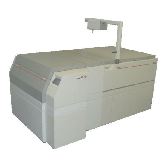
AGFA Avantra 36/44 Manuals
Manuals and User Guides for AGFA Avantra 36/44. We have
1
AGFA Avantra 36/44 manual available for free PDF download: Service Manual
AGFA Avantra 36/44 Service Manual (521 pages)
Brand:
AGFA
| Category:
Printer
| Size: 4.21 MB
Table of Contents
Table of Contents
3
Index
9
Olp
10
Specifications
11
Introduction
13
About this Manual
13
Warnings, Cautions, and Notes
13
Imagesetter Safety Information
14
Laser Safety
14
Labeling
15
On-Line Processor (OLP) Safety Information
16
Manual Overview
17
Service Manual Audience
17
Product Description
20
Glossary of Acronyms
22
Section 1: Imagesetter
24
Chapter 1: Imagesetter Installation Procedures
25
Customer Pre-Site Checklist
25
Introduction
25
Service Engineer Installation Procedure
28
Pre-Installation Checks
28
Unpacking the Imagesetter
29
Unlocking and Installing the Imagesetter
37
Checking the System
46
Customer Application Training
48
Chapter 2: Imagesetter Functional Analysis
50
Introduction
50
Electronics Overview
52
System Overview
52
Electronics Packaging
53
System Architecture
53
Digital Engine Controller (DEC)
56
Operator Control Panel
57
Micro-Controller
58
Ocp Flashrom
58
Keypad
59
Liquid Crystal Display (LCD)
59
Olp/Bridge Interface
59
Speaker (Audio Interface)
59
Carriage Sensor Driver Module (CSDM)
59
Sensor Driver Module (SDM)
60
SDM to DEC Interface
61
Laser Driver Module (LDM)
62
Power Supply
63
Additional Voltages
63
Power Distribution
63
Power Good
63
Optical System Overview
64
Spot Generation Module
65
Laser Diode Mount
66
Polarizer
66
Spot Forming Lens
66
Spot Size Changer
66
Beam Compressor
67
Weak Lens
67
Spin Motor Module
67
Encoder
68
Mirror
68
Spin Motor
68
Linear Carriage Transport Overview
68
Carriage Assembly
68
Carriage Home Position Sensor
70
Inner Shrouds
70
Linear Bearing Guideway
70
Vacuum System
72
Media Transport System Overview
74
Supply Side Mechanics
75
Powered Media Take-Up Cassette
76
Media Punch/Clamp Assembly
77
Take-Up Drive Assembly
78
Media Cutter Assembly
80
Supply Cassette
81
General Description
83
Humidifier Option Overview
83
Humidifier Sub-Assembly
83
Humidifier Electronics Module
84
Fan Control Circuit
85
Humidifier PC Board: LED Descriptions
86
Interface Connections
86
Software Functionality
86
Humidifier Option: Warnings and Indications
87
Humidity Low Indicator
87
Water Supply Empty Alert
87
Chapter 3: Imagesetter Diagnostics and Vacuum System Troubleshooting Guide
88
Introduction
88
Power-Up Boot Diagnostics
89
Power-Up Boot Diagnostics Overview
89
Power-Up Boot Sequence
90
Error Reporting
92
Automatic Dial-Out Feature
98
Boot Error Codes
100
OCP Run-Time Application Errors
102
Avantra Diagnostic Program (PC)
104
Equipment Requirements
104
Software Installation
105
Starting the Program
106
Functions
113
Settings
123
Save and Restore System Parameters
136
Remote Diagnostics
148
Equipment Requirements
148
Hardware Configuration
150
Vacuum System Troubleshooting Guide
154
Volt Sensing Relay Adjustment Procedure
158
Chapter 4: Imagesetter Component Removal/Replacement Procedures
160
Introduction
160
Covers
162
Right/Left Side Covers
162
Top, Middle and Bottom Front Panels
164
Electronic Enclosure Cover
167
Media Transport Removal/Replacement Procedures
168
Take-Up Light Shield
168
Outer Take-Up Drive (Nip) Assembly
169
Inner Take-Up Drive (Nip) Assembly
170
Inner Take-Up Drive (Nip) Motor
173
Take-Up Jam Sensor
175
Take-Up Punch Assembly
177
Cutter Assembly
179
Cutter Motor
181
Take-Up Media Present Detector
182
Supply Jam and Media Present Sensors
183
Electrical Removal/Replacement Procedures
183
Digital Engine Controller (DEC) PCB
184
Carriage Sensor Driver (CSDM) PCB
187
Operator Control Panel Assembly
189
The Supply and Take-Up Sensor Driver Modules PCB (Sdms)
191
Power Supply
193
Main Power Switch
195
Exhaust Fan
197
Intake Fan
198
Carriage Drive Removal/Replacement Procedures
199
Carriage Transfer Tool Installation
199
Carriage Assembly
201
Opto-Mechanical Removal/Replacement Procedures
204
Light Shields (Right and Left)
204
Spin Motor Module (SMM)
206
Spot Generation Module (SGM)
208
Spot Size Sensor
209
Polarizer Sensor
210
Beam Compressor Motor
211
Aperture Wheel Motor
212
Weak Lens Motor
213
Focus Sensor
214
Media Transport Removal/Replacement Procedures
216
Supply Drive Servo Motor
217
Supply Cassette a or B Rewind Motors
220
Supply Spindle Select Motor
221
Supply Spindle Select A/B Sensors
223
Supply Roller Removal and Installation
225
The Vacuum System
227
Vacuum Pump
228
Vacuum Valves
229
Vacuum Board
230
Chapter 5: Imagesetter Alignment
233
Introduction
233
Beginning of Line (BOL) Alignment Procedure
234
Exposure Adjustment Procedure
236
Carriage Home Position Alignment Procedure
237
Focus Alignment
239
System Leveling Procedure
242
Pulse Width Modulation (PWM) Adjustment Procedure
243
Voltage Check Procedure
243
Carriage Encoder Alignment Procedure
246
Supply Motor Offset Alignment Procedure
246
Take-Up Cassette Clutch Adjustment Procedure
248
A/B Roller and Sensor Adjustment
249
Feed Motor Calibration Test
249
Slack Loop Test Procedure
253
Chapter 6 : Imagesetter Preventive Maintenance
256
General Preventive Maintenance Requirements
256
Mechanical Inspection
256
Operational Inspection
259
Cleaning
260
Introduction
256
Appendix A: Specifications
264
Appendix B Spare Parts
266
Index
270
Section II: Bridge
282
Chapter 1: Bridge Installation
283
Introduction
283
Removing the Imagesetter Top Cover
284
Attaching the Capture Bar to the Bridge
287
Raising and Lowering the Bridge into the Imagesetter
289
Attaching the Bridge to the Imagesetter
291
Attaching the Bridge Foot
291
Attaching the Gas Shocks
294
Adjusting the Detent Plate
296
Aligning the Solid Stops
299
Setting up the DEC to Bridge/Buffer Interface
300
Attaching the Ground Wires
303
Chapter 2: Bridge Functional Analysis
305
Introduction
305
Chapter 3: Bridge Debugger Diagnostic Tool
306
Introduction
306
Setting up the Debugger Port
307
Bridge Debugger User Interface
308
Bridge Unlock Sequence
308
Terminal Code Identifiers
308
Bridge States
309
Bridge Error Codes
310
Bridge State Responses
310
Bridge Sensor Status
311
Bridge Parameters
312
Bridge/Buffer Commands
312
Introduction
314
Removing and Replacing the Bridge Foot
315
Media Purchase Sensor
316
Bridge Loop Sensor
316
Upper Bridge Servo Motor
317
The Activator Switch
319
The Bridge up Sensor
320
Bridge Shuttle Motor
321
Shuttle Light and Heavy Sensors
323
Appendix A Spare Parts
324
Section III: Buffer
327
Chapter 1: Buffer Installation
328
Introduction
328
Buffer Installation Procedures
329
Unpacking the Buffer
329
Unlocking the Buffer
333
Installing the Buffer to the Imagesetter
337
Aligning the Buffer Carriage
346
Chapter 2: Buffer Component Removal/Replacement
349
Introduction
349
Buffer Home and Buffer Processor Sensors
350
Buffer Purchase Sensor
351
Buffer Carriage Drive Motor
352
Buffer Roller Driver Motor
353
Appendix A Spare Parts
356
Section IV: On-Line Processor
359
Chapter 1: OLP Installation
360
Introduction
360
Tools Required for OLP Unpacking
360
Electrical
361
Floor Load
361
OLP Work Space Requirements
361
Space
361
Operational
362
OLP Unpacking Procedures
362
OLP Inventory
362
Rear Exit Panel
362
Rear Top Side Panel
362
Receiver Basket
362
Right Lower Door
362
Tools Required for OLP Unpacking
362
Opening and Unpacking the Parts Crate
364
Unpacking and Preparing the OLP Engine
367
Installation Procedures
372
Tools and Equipment Required for Installation
372
Attaching the Legs and Feet
372
Connecting the Water Supply and Drainage
374
Rear Leveler Feet
374
Support Leg
374
Steps for Connecting Water Supply
375
Tank Capacity, Water
375
Temperature Range
375
Connecting the Electrical Supply
376
Rewiring
378
Leveling and Attaching the OLP to the Buffer
379
Attaching the Panels and Covers
383
Striker Plate
384
Red (Developer) Hose
385
Right Side Cover
387
Top Covers
393
Introduction
394
Ready Mode
394
Temperature Control
394
Description of OLP Boot-Up Procedures
395
Idle Mode
395
OLP Standby Mode
395
Operate Mode
395
Ready Mode
395
The OLP Jog Function
396
Electronics
396
The LUTH Computer Board (LCB)
396
The LUTH Power Board (LPB)
399
Operating Parameters
401
Optical Interrupter
401
Sensors
401
Temperature Sensor
401
The Agfa Terminal Board (ATB)
401
The LUTH Motor Board (LMB)
401
OLP Racks
402
Immersion Heaters
402
Replenishment
402
Temperature Control
402
Timed Replenishment
402
Chapter 3: OLP Component Removal/Replacement
404
Introduction
404
Dryer Section Temperature
404
OLP Com
404
Drive Motor
405
Cpu-Olp
407
LUTH Motor Control Board
412
LUTH Rectifier Board (LRB)
413
Power Board
414
Circulation Pump
417
Developer or Fixer Replenishment Pumps
418
Heating Element
420
Wet Section Temperature Sensor
421
Dryer Section Temperature Sensor
422
Dryer Blower Motor Assembly
423
Dryer Heater Element
423
Dryer Blower
426
Drive Belt
429
Entry Rack Assembly
429
Drive Shaft
430
Chapter 4: OLP Maintenance
433
How to Use
433
Introduction
433
Replenishment Pumps
433
Service Program
433
Setting the Jumpers
433
Checking Sensor Operation
434
Servicing
434
Checking Operation of the LCB
435
Checking the Battery
436
Setting the Jumpers
437
Calibrating/Jumper Settings
438
LUTH Motor Control Board (LMB) 24V DC (P/N 5202Y000100)
439
LUTH Motor Control Board (LMB) 180V DC (P/N 5203Y4000200)
443
Replenishment Pumps Calibration
444
The Service Program
446
Troubleshooting
446
Service Program Codes
448
How to Use the Repair Method Tables
449
Circulation Pumps
451
Repair Steps
453
Switches and Sensors
456
Appendix C: Wiring Diagrams
458
Introduction
458
Tank Capacity
459
Wiring Diagrams
484
Section IV: On-Line Processor
489
Unpacking the Crane
493
Crane Installation Procedures
494
The Mounting Plate and Boom
494
Mounting the Head
498
Chapter 2: Crane Component Removal / Replacement
503
Introduction
503
Crane Removal/Replacement Procedures
504
Crane On/Off Switch
504
Crane Motor
509
Crane Slack Safety Switch
511
Crane Cable
512
Appendix A Spare Parts
517
Advertisement
Advertisement
Related Products
AGFA Avantra 36S/44S
AGFA CG Triumvirate 3R20P
AGFA CG Triumvirate 3R20
AGFA FOTOLOOK 3.6
AGFA Rapiline type 3 Offline
AGFA Pixium 3543 EZ
AGFA CR 30-XmTM
AGFA DX-D 35C
AGFA DX-D 30C
AGFA SNAPSCAN 300
AGFA Categories
Medical Equipment
Printer
Scanner
Digital Camera
Measuring Instruments
More AGFA Manuals
Login
Sign In
OR
Sign in with Facebook
Sign in with Google
Upload manual
Upload from disk
Upload from URL