
Related Manuals for IBM SAN512B-6


Summary of Contents for IBM SAN512B-6
- Page 1 IBM Storage Networking SAN512B-6 Installation, Service, and User Guide MTM Service information: 8961-F08 SC27-8966-02...
- Page 3 IBM Storage Networking SAN512B-6 Installation, Service, and User Guide MTM Service information: 8961-F08 SC27-8966-02...
- Page 4 Before you use the information in this publication, be sure to read the general information under “Notices” on page 251. Copyright Portions Copyright © 2016 Brocade Communications Systems, Inc. All Rights Reserved. © Copyright IBM Corporation 2017. US Government Users Restricted Rights – Use, duplication or disclosure restricted by GSA ADP Schedule Contract with IBM Corp.
-
Page 5: Table Of Contents
IBM and Brocade product matrix. . xxii Powering down the chassis . . 56 Chapter 1. Introducing the SAN512B-6 Chapter 5. Installing Transceivers and Product features . Cables ....57 Hardware components . - Page 6 . 151 Appendix A. SAN rack ..209 Preparing for WWN card replacement . . 152 Hot-swap replacement . . 153 Installing the IBM SAN rack . . 209 SAN512B-6 Installation, Service, and User Guide...
- Page 7 Step 1. Position the rack . . 210 Homologation statement . 252 Step 2. Level the rack. . 210 Electronic emission notices . . 252 Step 3. Attach the stabilizers . . 211 Federal Communications Commission Statement 252 Step 4. Attach the rack to a concrete floor . .
- Page 8 SAN512B-6 Installation, Service, and User Guide...
-
Page 9: Figures
Figures Port side of the SAN512B-6 (sample CR32-8 core routing blade port numbering configuration) . ICL cable connections (sample configuration) Nonport side of the SAN512B-6 (sample Core-edge ICL topology . . 122 configuration) . Removing and installing a core routing blade 126 Rack kit parts . - Page 10 SAN512B-6 Installation, Service, and User Guide...
-
Page 11: Tables
Tables Brocade and IBM product and model number 2870 W AC Power supply LED descriptions matrix . . xxii 2870 W AC Power supply LED descriptions Facility requirements . . 10 (continued). . 82 Installation tasks, time, and items required Fan assembly LED descriptions . - Page 12 SAN512B-6 Installation, Service, and User Guide...
-
Page 13: Read This First
GUI. Vendor software This product includes certain vendor software that is not covered under the IBM license agreement. IBM makes no representation about the accessibility features of © Copyright IBM Corp. 2017... -
Page 14: How To Send Your Comments
Department GZW 9000 South Rita Road Tucson, Arizona 85744–0001 U.S.A. When you send information to IBM, you grant IBM a nonexclusive right to use or distribute the information in any way it believes appropriate without incurring any obligation to you. -
Page 15: Safety And Environmental Notices
Safety Notices publication that is shipped with this product. The following notices and statements are used in IBM documents. They are listed below in order of increasing severity of potential hazards. Follow the links for more detailed descriptions and examples of the danger, caution, and attention notices in the sections that follow. - Page 16 In addition, anti-rotation devices or lock washers must be used with all screw connections for the grounding wire. SAN512B-6 Installation, Service, and User Guide...
-
Page 17: Danger Notices
CAUTION: All devices with AC power sources are intended for installation in restricted access areas only. A restricted access area is a location where access can be gained only by service personnel through the use of a special tool, lock and key, or other means of security. CAUTION: Before plugging a cable into any port, be sure to discharge the voltage stored on the cable by touching the electrical contacts to ground... - Page 18 18-32 kg (39.7-70.5 lbs) DANGER A fully populated chassis weighs approximately 145.83 kg (321.5 lbs) and requires a hydraulic or assisted lift to install it. 18-32 kg (39.7-70.5 lbs) SAN512B-6 Installation, Service, and User Guide...
- Page 19 DANGER If a lift tool with a capacity of at least 350 lbs is not available, the director chassis must be depopulated completely before installing 18-32 kg (39.7-70.5 lbs) it into the rack. Remove the power supplies, fan modules, all of the blades, the cable management comb, and the chassis door (if equipped).
-
Page 20: Safety Labels
All fiber-optic interfaces use Class 1 lasers. DANGER Use only optical transceivers that are qualified by IBM and comply with the FDA Class 1 radiation performance requirements defined in 21 CFR Subchapter I, and with IEC 825 and EN60825. Optical products that do not comply with these standards might emit light that is hazardous to the eyes. - Page 21 DANGER Rack-mounted devices are not to be used as a shelf or work space. (L002) DANGER Multiple power cords. This product might be equipped with multiple power cords. To remove all power to the device, disconnect all power cords. (L003) DANGER High voltage present.
-
Page 22: Attention Notices
Store ESD-sensitive components in antistatic packaging Rack safety Environmental notices Use the environmental statements and warning in this section to guide you when using this product and in properly disposing of the product and its components. SAN512B-6 Installation, Service, and User Guide... -
Page 23: About This Document
It describes how to install, service, and use the IBM Storage Networking SAN512B-6 (machine type-models 8961-F08 Switch). Throughout this document, the product is referred to as the SAN512B-6, or simply the switch. This document has been created to include information specific to SAN512B-6 switches running on Fabric OS version 8.0.1 or later. -
Page 24: Ibm And Brocade Product Matrix
(FOS) publications, you will notice that the model numbers reflect the corresponding Brocade products. Table 1 provides a product matrix to correlate the Brocade products and models to the IBM product names and machine types and model numbers. Products withdrawn from marketing are not listed. -
Page 25: Chapter 1. Introducing The San512B-6
Chapter 1. Introducing the SAN512B-6 This chapter provides the following information: v “Product features” v “Hardware components” on page 2 v “Port-side view of device” on page 3 v “Port-side slot numbering” on page 5 v “Nonport-side view of the device” on page 5... -
Page 26: Hardware Components
- The 16-Gbps SFP+ transceivers support speeds of 4, 8, and 16 Gbps. - The 4x32-Gbps QSFP+ transceivers on the core routing blades provide four 32–Gbps inter-chassis links (ICL) clustered in a single quad connector and cable. SAN512B-6 Installation, Service, and User Guide... -
Page 27: Port-Side View Of Device
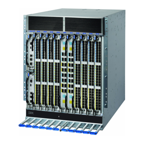
Port-side view of device The following illustration shows the port-side view of the SAN512B-6 with installed blades identified. Note that SX6 extension blades are not shown in the following illustration, but would install in the same slots as the FC32-48 port blade. -
Page 28: Port Side Of The San512B-6
4 - Cable management comb 5 - Control processor blades (CPX6) – slot 1 (upper), slot 2 (lower) Figure 1. Port side of the SAN512B-6 (sample configuration) Notes: v Depending on the fans and power supplies installed, airflow can be from the port side to the nonport side of chassis or from the nonport side to the port side of the chassis. -
Page 29: Port-Side Slot Numbering
Port-side slot numbering The SAN512B-6 contains 10 full-height slots and two half-height slots, for a total of 12 slots. Facing the port side of the device, the half-height slots are on the left, numbered 1 (top slot) and 2 (bottom slot). The remaining full-height slots are numbered 3 through 12, counting from left to right of chassis. -
Page 30: Nonport Side Of The San512B-6
Figure 2. Nonport side of the SAN512B-6 (sample configuration) 1 - WWN bezel (WWN cards behind) 2 - Power supply assembly 3 - Fan assembly 4 - 2AWG Panduit LCD2-14AF lug for building ground connection Depending on fans and power supplies installed, airflow can be from the port side to the nonport side of the chassis or the nonport side to the port side of chassis. -
Page 31: Chapter 2. Preparing For The Installation
CAUTION: Make sure the airflow around the front, sides, and back of the device is not restricted. CAUTION: To protect the serial port from damage, keep the cover on the port when not in use. © Copyright IBM Corp. 2017... - Page 32 CAUTION: Use a separate branch circuit for each power cord, which provides redundancy in case one of the circuits fails. DANGER High Touch Current. Earth connection essential before connecting supply. SAN512B-6 Installation, Service, and User Guide...
-
Page 33: Lifting Precautions
Lifting precautions CAUTION: Use safe lifting practices when moving the product. 18-32 kg (39.7-70.5 lbs) CAUTION: A fully populated chassis weighs approximately 145.83 kg (321.5 lbs) and requires a hydraulic or assisted lift to install it. 18-32 kg (39.7-70.5 lbs) Note: Do not attempt to lift the device by the protective cover attached to the air vents on the nonport-side of the chassis. -
Page 34: Facility Requirements
PDUs to power source. Thermal Ensure that the air intake and exhaust vents have a minimum of 5.1 cm (2 in.) of airspace. Ensure that the air intake temperature is less than 40°C (104°F) during operation. SAN512B-6 Installation, Service, and User Guide... -
Page 35: Time And Items Required For Installation
Table 2. Facility requirements (continued) Type Requirements Rack (when Ensure that these airflow requirements are met: rack-mounted) v Plan to install the device with the air-intake side facing the cool air aisle. The device can be installed facing either direction if serviceability and cooling requirements are met. -
Page 36: Installation Tasks, Time, And Items Required
20-30 minutes or longer if SFP+ and QSFP28 optical needed. you are using high-density transceivers as needed. port blades. Attaching fiber-optic cables, 2-3 hours Fiber-optic cables, cable ties, cable ties, and cable guides. and cable management comb. SAN512B-6 Installation, Service, and User Guide... -
Page 37: Quick Installation Checklists
Quick installation checklists These checklists provides a high-level overview of the basic installation process from the planning stage to the point where the device comes online and is ready to be deployed. Completing all the tasks in the suggested order ensures successful installation. - Page 38 Establish an Ethernet connection By establishing an Ethernet connection, you can complete the device configuration using a serial session, Telnet, or management application, such as IBM Network Advisor. Refer to“Establishing an Ethernet connection to the device” on page 49. Optional: Configure the DNS Use the dnsconfig command to create DNS server entries.
-
Page 39: Items Shipped
Verify that you have the following items. Save shipping cartons and packaging in the event you need to return the device. Packaged in device shipping carton: v SAN512B-6 switch with shipping tray v Packing foam v Antistatic plastic v Inner foam Packaged in device shipping carton or separate carton. - Page 40 SAN512B-6 Installation, Service, and User Guide...
-
Page 41: Chapter 3. Mounting The Device
18-32 kg (39.7-70.5 lbs) DANGER Make sure the airflow around the front, sides, and back of the device is not restricted. © Copyright IBM Corp. 2017... - Page 42 18-32 kg (39.7-70.5 lbs) CAUTION: You can connect the device to building ground by connecting an appropriate 2 AWG wire from a grounded connection to the 2AWG Panduit LCD2-14AF lug on the nonport-side of the device. SAN512B-6 Installation, Service, and User Guide...
-
Page 43: Unpacking And Transporting The Device
Unpacking and transporting the device About this task Use the following procedure to unpack and install your device. DANGER A fully populated chassis weighs approximately 145.83 kg (321.5 lbs) and requires a hydraulic or assisted lift to install it. If a lift tool with a capacity of at least 350 lb is not available, the director chassis must be depopulated completely before installing it into the rack. -
Page 44: Port-Side Slot Numbering
Port-side slot numbering The SAN512B-6 contains 10 full-height slots and two half-height slots, for a total of 12 slots. Facing the port side of the device, the half-height slots are on the left, numbered 1 (top slot) and 2 (bottom slot). The remaining full-height slots are numbered 3 through 12, counting from left to right of chassis. -
Page 45: Parts List
v Slotted (flat blade) screwdriver v Hydraulic or assisted lift with a minimum raise of 140 cm (55 in.) and a minimum capacity of 158.76 kg (350 lbs) DANGER If a lift tool with a capacity of at least 350 lbs is not available, the director chassis must be depopulated completely before installing it into the rack. -
Page 46: Parts List - Nebs Kit
This kit is only supported for specific devices, and may not apply to the device that you are installing. Note: Depending on the device and installation, not all of the parts may be used. SAN512B-6 Installation, Service, and User Guide... -
Page 47: Assembling The Rack Hardware
Verify that the items listed in the following figure are included in the NEBS kit. Figure 4. NEBS kit parts list 1. Left cable comb assembly (1) 2. Right cable comb assembly (1) 3. Air filter (1) 4. Chassis door (1) 5. -
Page 48: Left And Right Shelf Brackets Installed On Rails
Use eight screws with lock washers per bracket (four on each end). Tighten the screws to a torque of 80 in-lb (92 cm-kg). v For rails with square holes, do the following: SAN512B-6 Installation, Service, and User Guide... -
Page 49: Nut And Screw Locations For Mounting The Device
– Position the left and right rack mount shelf brackets and attach them to the rack rails. Use eight screws and alignment washers per bracket (four on each end). Tighten the screws to a torque of 80 in-lb (92 cm-kg). Figure 6. -
Page 50: Installing The Device In The Rack
(1.58 cm) screws per rail. Tighten the screws to a torque of 32 in-lb (37 cm-kg). Refer to Figure 5. Note: Do not use the top or bottom holes of the mounting bracket because the screw heads will interfere with the door. SAN512B-6 Installation, Service, and User Guide... -
Page 51: Positioning The Device For Installation In A Rack
Figure 7. Positioning the device for installation in a rack 1 - Rack 2 - Nonport side of device Chapter 3. Mounting the Device... -
Page 52: Installing The 14U Chassis Mid-Mount Rack Kit For Two-Post Racks
Allow approximately one hour to unpack and install a chassis in a rack. The following tools are required when installing the 14U Chassis Mid-Mount Rack Kit for Two-Post Racks. v Torque wrench with #2 Phillips screwdriver tip. SAN512B-6 Installation, Service, and User Guide... -
Page 53: Parts List
v Flathead screwdriver. v Hydraulic or assisted lift with a minimum raise of 140 cm (55 in.) and a minimum capacity of 158.76 kg (350 lbs) DANGER If a lift tool with a capacity of at least 350 lbs is not available, the director chassis must be depopulated completely before installing it into the rack. -
Page 54: Assembling The Rack Hardware
5 - Screw, 10-32 x 3/8”, pan head Phillips, ST, zinc (requires a torque of 32 inch-pounds) Note: Not all parts may be used with certain installations depending on the device type. Assembling the rack hardware About this task Perform the following steps to assemble the rack hardware. SAN512B-6 Installation, Service, and User Guide... -
Page 55: Attaching The Rear Tray To The Rack Rails
Procedure 1. Attach the rear tray (with or without adapter, as required) to both rack rails. Orient the tray (refer the following figure) and use nine screws (Item E) for each rail. 2. Attach the front tray to both rack rails. Orient the tray (Figure 3) and use nine screws (Item E) for each rail. -
Page 56: Installing The Device In The Rack
Use safe lifting practices when moving the product. 18-32 kg (39.7-70.5 lbs) Note: A fully populated device requires a hydraulic or assisted lift to install into a rack. Perform the following steps to load the device into the mid-mount trays. SAN512B-6 Installation, Service, and User Guide... - Page 57 Procedure 1. Ensure that the door is removed from the port side of the device. For instructions, refer to the door removal and replacement procedures in your device installation guide. 2. Orient the device (refer the following figure) and use a hydraulic lift to raise it to the level of the trays.
-
Page 58: Removing The Protective Cover
Removing the protective cover About this task The chassis ships with a protective cover installed over the air vents at the top of the port side of the chassis. SAN512B-6 Installation, Service, and User Guide... -
Page 59: Removing Protective Cover From San512B-6
Remove this cover by removing the Phillips screws securing it to the mounting bracket on each side of the chassis. Figure 14. Removing protective cover from SAN512B-6 Note: Do not attempt to lift or support the chassis by the protective cover. - Page 60 SAN512B-6 Installation, Service, and User Guide...
-
Page 61: Chapter 4. Initial Setup And Verification
CP blade. Configure IP addresses for the device. Configure an IP address and subnet mask for a chassis management connection. Configure IP addresses, host names, subnet masks, and gateway addresses for both control processor (CP) blades. © Copyright IBM Corp. 2017... -
Page 62: Items Required
A workstation computer with an installed terminal emulator application, such as HyperTerminal for Windows. v An unused IP address with corresponding subnet mask and gateway address. v A serial cable (provided) with an RJ-45 connector. v An RJ-45 to DB-9 adapter. SAN512B-6 Installation, Service, and User Guide... -
Page 63: Providing Power To The Device
v Three Ethernet cables (including one spare). v Access to an FTP server or USB device for backing up (uploading) or downloading the device configuration or collecting supportsave output data (optional). v A USB drive for collecting supportsave output data (optional) Providing power to the device Before you begin Before connecting power, refer the following. -
Page 64: Connecting Power Cord To Hvac/Hvdc Power
DC (HVAC/HVDC) power supply. This power supply converts high-voltage DC or AC input to appropriate DC power for the device. Make sure that you observe the electrical caution and danger statements in “Safety precautions” on page 7 when connecting this power supply. SAN512B-6 Installation, Service, and User Guide... - Page 65 Note: The equipment installation must meet NEC/CEC code requirements. Consult local authorities for regulations. Note: Power is supplied to the device as soon as the first power supply is connected to a power source. CAUTION: The maximum input voltage for connection to the HVAC/HVDC power supply should not exceed 305 VAC and 400 VDC.
- Page 66 Note that the connector's latch should be positioned under the connector and will latch when the power cord connector is fully inserted into the power supply. SAN512B-6 Installation, Service, and User Guide...
- Page 67 1. Power cable 2. Connector latch 8. Attach the cable restraint cover under the power cord connector using its two torx head screws (refer to step 4). Note: This retainer cover protects the power cord from being accidentally unlatched and disconnected from the power supply. 9.
- Page 68 Note: Do not connect the device to the network until the IP addresses are configured. 13. After POST is complete, verify that the power LEDs on blades and other FRUs are green. SAN512B-6 Installation, Service, and User Guide...
- Page 69 For information about LED patterns, refer to Chapter 6, “Monitoring the switch,” on page 69. 14. Ground the chassis by attaching a ground wire from facilities ground to an appropriate crimp connector and attaching the connector to the 2AWG Panduit LCD2-14AF lug located to the left of the bottom fan assembly near the bottom of the chassis.
-
Page 70: Establishing A Serial Connection To The Device
The active CP is indicated by an illuminated blue LED on the CP blade front panel. Note: The console, or serial port is intended primarily for the initial setting of the IP address and for service purposes. SAN512B-6 Installation, Service, and User Guide... - Page 71 3. Use the serial cable provided with the device to connect the console (serial) port on the active CP to a computer workstation. Note: The active CP is indicated by an illuminated blue LED, labeled "Active," on the CP blade front panel. If the serial port on the workstation is RJ-45 instead of RS-232, remove the adapter on the end of the serial cable and insert the exposed RJ-45 connector into the RJ-45 serial port on the workstation.
-
Page 72: Configuring The Ip Addresses
Enter required information at the prompts. Specify the -chassis IP address. The -sw 0 IP address is not valid on this device. Note: The addresses 10.0.0.0 through 10.0.0.255 are reserved and used internally by the device. External IPs must not use these addresses. SAN512B-6 Installation, Service, and User Guide... -
Page 73: Establishing An Ethernet Connection To The Device
After establishing an Ethernet connection, you can complete the device configuration using a serial console connection, Telnet connection, or management applications, such as Web Tools or IBM Network Advisor. Perform the following steps to establish an Ethernet connection to the device. -
Page 74: Setting The Domain Id
You can synchronize the local time of the principal or primary fabric configuration server (FCS) device to that of an external Network Time Protocol (NTP) server. Perform the following steps to set the date and time. SAN512B-6 Installation, Service, and User Guide... -
Page 75: Setting The Time Zone
Procedure 1. Log into the device using one of the following methods: v A serial console connection to the active CP blade. The active CP is indicated by an illuminated blue LED on the blade front panel. v A Telnet session using the chassis management IP address. 2. -
Page 76: Synchronizing Local Time With An External Source
2. Log into the device using admin. If you have not changed the default password, usepassword. 3. Enter the tsClockServer ipaddr command. The ipaddr variable represents the IP address of the NTP server that the device can access. This argument is optional; by default, the value is "LOCL". SAN512B-6 Installation, Service, and User Guide... -
Page 77: Customizing The Chassis And Switch Name
switch:admin> tsclockserver 192.168.126.60 Updating Clock Server configuration...done. Updated with the NTP servers Customizing the chassis and switch name About this task The switch name of the device can be up to 31 characters long and must begin with a letter. It can include letters, numbers, hyphens, and underscore characters. The chassis name and switch name of the device can be up to 31 characters long;... -
Page 78: Verifying Installed Licenses And License Key
Verifying correct operation About this task Perform the following steps to verify correct operation of the device. Procedure 1. Check the LEDs of all power supplies, fans, and blades to verify that all are functional. SAN512B-6 Installation, Service, and User Guide... -
Page 79: Backing Up The Configuration
2. Log into the device using one of the following methods: v A serial console connection to the active CP blade. The active CP is indicated by an illuminated blue LED on the blade front panel. v A Telnet session using the chassis management IP address. 3. -
Page 80: Powering Down The Chassis
2. Power off the chassis by disconnecting all power cords or switching off rack power source. Note that power supply LEDs will continue to flash green briefly after disconnecting power until power supply is completely off. SAN512B-6 Installation, Service, and User Guide... -
Page 81: Chapter 5. Installing Transceivers And Cables
Fixed SR4/LR4/ER4 CR32-8 core routing 4x16 Gbps QSFP, SWL, Fixed (each 16 Gbps blade channel) 4x32 Gbps QSFP28, SWL Fixed (each 32 Gbps channel) 4x16 Gbps 2 km QSFP, LWL Fixed (each 16 Gbps channel) © Copyright IBM Corp. 2017... -
Page 82: Core Routing Blades
The following notes apply to QSFP transceivers on core routing blades. v You cannot connect an ICL between a 4x32 Gbps QSFP on a SAN512B-6 core blade and a 16-Gbps QSFP on a DCX 8510 core routing blade. You must use a 4x16 Gbps QSFP on the SAN512B-6 blade. -
Page 83: Km Qsfp 16 Gbps With Integrated Cable
32 Gbps and cannot be configured at 16 Gbps for Fabric OS v8.0.1. Therefore, you cannot connect an ICL between a 32 Gbps transceiver on a SAN512B-6 core blade and a 16 Gbps QSFP transceiver on a SAN384B-2 or SAN768B-2 core routing blade. You must connect between 16 Gbps transceivers on each blade. -
Page 84: Time And Items Required
The installation or replacement procedure for one transceiver takes less than 5 minutes. Ensure that the following items are available: v Required number of compatible power cables v Required number of supported IBM-branded transceivers v Required number of compatible fiber-optic cables v Optical transceiver extraction tool (for 10 Gbps transceiver only) Note: Most devices come with a transceiver extraction tool and holster. -
Page 85: Precautions Specific To Transceivers And Cables
All fiber-optic interfaces use Class 1 lasers. CAUTION: Use only optical transceivers that are qualified by IBM and comply with the FDA Class 1 radiation performance requirements defined in 21 CFR Subchapter I, and with IEC 825 and EN60825. Optical products that do not comply with these standards might emit light that is hazardous to the eyes. -
Page 86: Cable Management
Installing an SFP+ transceiver About this task The device supports only IBM-qualified transceivers. If you use an unqualified transceiver, the switchshow command output shows the port in a Mod_Inv state. Fabric OS also logs the issue in the system error log. To insert an SFP+ transceiver,... -
Page 87: Installing An Sfp+ Transceiver With Pull Tab
Figure 20. Installing an SFP+ transceiver with pull tab into blade port 1 - Pull tab 2 - Transceiver v If transceiver has a bail latch mechanism (10 GbE transceivers), ensure that the bail (wire handle) is in the unlocked position, grasp the transceiver, and push it into the port until firmly seated. -
Page 88: Replacing An Sfp+ Transceiver
Pull the transceiver out from the port slightly using the bail, and then gasp the transceiver with your fingers and slide it straight out of the port. SAN512B-6 Installation, Service, and User Guide... -
Page 89: Installing A Qsfp Transceiver
Installing a QSFP transceiver About this task The device supports only IBM-qualified transceivers. If you use an unqualified transceiver, the switchshow command output shows the port in a Mod_Inv state. Fabric OS also logs the issue in the system error log. Also note the following: v Each QSFP contains four individual 16 Gbps or 32 Gbps ports. -
Page 90: Replacing A Qsfp Transceiver
Replacing a QSFP transceiver About this task The device supports only IBM-qualified transceivers. If you use an unqualified transceiver, the switchshow command output shows the port in a Mod_Inv state. Fabric OS also logs the issue in the system error log. Also note the following:... -
Page 91: Installing A Qsfp Optical Transceiver Into Blade
v Each QSFP contains four individual 16 Gbps or 32 Gbps ports. Be aware that any problems with one port could affect all four ports in the quad if the QSFP must be replaced. v Although installation and removal procedures are the same for QSFP transceivers installed in port blades and extension blades, these transceivers are not interchangeable between the two blade types. -
Page 92: Verifying The Operation Of New Transceivers
For output examples and additional information on Fabric OS commands, refer to “Using monitoring commands” on page 85 and the Fabric OS Command Reference. For more information about error messages, refer to the Fabric OS Message Reference. SAN512B-6 Installation, Service, and User Guide... -
Page 93: Chapter 6. Monitoring The Switch
“Running diagnostic tests” on page 103 Interpreting port blade LEDs Refer to the following illustration and table to interpret the LED patterns for the FC32-48 blade. The LED patterns will temporarily change during POST and other diagnostic tests. © Copyright IBM Corp. 2017... -
Page 94: Fc32-48 Port Blade Leds
No light (LED is off) Blade is not powered on. Ensure that the blade is Power firmly seated, with ejectors pushed in fully to center of blade and captive screw for each ejector fully tightened. SAN512B-6 Installation, Service, and User Guide... - Page 95 Table 10. Port blade LED descriptions (continued) LED purpose Color Status Recommended action No light (LED is off) Blade is either healthy or Verify that the power LED does not have power. is on. Status Steady amber Blade is faulty. Ensure that the blade is firmly seated and check the status by entering the...
-
Page 96: Interpreting Extension Blade Leds
5 - Right 1 or 10 GbE port status LED 6 - Left 1 or 10 GbE port status LED 7 - Right FC port status LED 8 - Left FC port status LED SAN512B-6 Installation, Service, and User Guide... -
Page 97: Extension Blade Led Descriptions
The following table describes the extension blade LED patterns and the recommended actions for those patterns. Table 11. Extension blade LED descriptions LED purpose Color Status Recommended action Steady green Blade is operational. No action required. No light (LED is off) Blade is not powered on. -
Page 98: Interpreting Control Processor Blade Leds
Interpreting control processor blade LEDs Refer to the following illustration and table to interpret the LED patterns on the CPX6 blade. The LED patterns may temporarily change during POST and other diagnostic tests. SAN512B-6 Installation, Service, and User Guide... -
Page 99: Cp Blade Led Descriptions
Figure 28. Control processor blade (CPX6) 1 - Blade power LED 2 - Blade status LED 3 - Chassis beacon LED 4 - Active (blue) CP LED 5 - 10/100/1000 Mb/s Ethernet port (MGMT) link status LED 6 - 10/100/1000 Mb/s Ethernet port (MGMT) link activity LED 7 - 10/100/1000 Mb/s Ethernet port (SERVICE) link status LED 8 - 10/100/1000 Mb/s Ethernet port (SERVICE) link activity LED Note: The 10 Gbps Base-T RJ45 Ethernet port, shown below the blade beacon LED,... - Page 100 NOTE: To force a persistent Ethernet link speed, enter the ifModeSet command. LED is on Ethernet link speed is No action required. 100/1000 Mb/s. Ethernet link is healthy and traffic is flowing through port. SAN512B-6 Installation, Service, and User Guide...
-
Page 101: Interpreting Core Routing Blade Leds
Table 12. CP blade LED descriptions (continued) LED purpose Color Status Recommended action Ethernet link activity No light (LED is off) No activity on link. Ensure that the blade has (10/100/1000 Mb/s port) power, the Ethernet cable is firmly seated, and the connected device is functioning. -
Page 102: Interpreting Wwn Card Leds
WWN cards. LEDs for WWN card 1 and WWN card 2 are located on the WWN card bezel between the power supplies on the nonport side of the device. The LED patterns may temporarily change during POST and other diagnostic tests. SAN512B-6 Installation, Service, and User Guide... -
Page 103: Interpreting Power Supply Leds
Refer to the following illustration and table to interpret the LED patterns on the power supply. The LED patterns may temporarily change during POST and other diagnostic tests. The SAN512B-6 can have up to four power supplies. Figure 31. 2870 W AC Power supply LED... - Page 104 LED will flash in a coded pattern to provide additional fault information. Record the sequence of flashes and status as defined in the table to provide to your support representative along with supportsave output data. SAN512B-6 Installation, Service, and User Guide...
- Page 105 Table 15. 2870 W AC Power supply LED descriptions LED purpose Color Status Recommended action No light (LED is off) Power supply does not Ensure that the power have incoming power and supply is firmly seated, Power status is not providing power to power cable is connected, the device.
-
Page 106: Interpreting Fan Assembly Leds
Interpreting fan assembly LEDs Refer to the following illustration and table to interpret the LED patterns on fan assemblies. The LED patterns may temporarily change during POST and other diagnostic tests. The SAN512B-6 has three fan assemblies. SAN512B-6 Installation, Service, and User Guide... -
Page 107: Fan Assembly Leds
Figure 32. Fan assembly LEDs 1 - Power LED 2 - Status LED Table 17. Fan assembly LED descriptions LED purpose Color Status Recommended action No light (LED is off) Fan assembly does not Ensure that the fan have power. assembly is firmly seated Power and has power. -
Page 108: Interpreting Post And Boot Results
Verify that the switch prompt displays when POST completes. If it does not display, POST was not successfully completed. Contact the device supplier for support. v Review the system error log using the errShow or errDump commands. SAN512B-6 Installation, Service, and User Guide... -
Page 109: Boot
Any errors detected during POST are written to the system log, which is accessible through the errShow command. For information about error messages, refer to the Fabric OS Message Reference. POST includes the following steps: Procedure 1. Preliminary POST diagnostics are run. 2. -
Page 110: Chassisshow
CP BLADE Slot: 2 Header Version: Power Consume Factor: -50W Power Usage: -41W Factory Part Num: 60-1003201-09 Factory Serial Num: DYK0338L00E Manufacture: Day: 7 Month: 10 Year: 2015 Update: Day: 23 Month: 3 Year: 2016 SAN512B-6 Installation, Service, and User Guide... - Page 111 Time Alive: 87 days Time Awake: 0 days SW BLADE Slot: 5 Header Version: Power Consume Factor: -420W Power Usage: -264W Factory Part Num: 60-1003373-01 Factory Serial Num: EAL0339L009 Manufacture: Day: 24 Month: 10 Year: 2015 Update: Day: 12 Month: 3 Year: 2016 Time Alive: 66 days Time Awake:...
- Page 112 Day: 15 Month: 2 Year: 2016 Time Alive: 68 days Time Awake: 2 days FAN Unit: 1 Fan Direction: Non-portside Intake Header Version: Power Consume Factor: -300w Factory Part Num: 60-1003203-03 Factory Serial Num: DYL0329L04R SAN512B-6 Installation, Service, and User Guide...
-
Page 113: Errdump And Errshow
Manufacture: Day: 3 Month: 10 Year: 15 Update: Day: 15 Month: 2 Year: 2016 Time Alive: 68 days Time Awake: 2 days FAN Unit: 2 Fan Direction: Non-portside Intake Header Version: Power Consume Factor: -300w Factory Part Num: 60-1003203-03 Factory Serial Num: DYL0329L02E Manufacture: Day: 10 Month: 10 Year: 15... -
Page 114: Fanshow
Note the following about this output: v A warm recovery typically does not disrupt traffic flow. v A cold recovery is usually a result of a reboot of the active CP, which disrupts traffic. SAN512B-6 Installation, Service, and User Guide... -
Page 115: Historyshow
v A lack of HA synchronization can be related to a firmware download in progress or that the device is recovering from a reboot or power-cycle. historyShow Use this command to display the entire history log, which includes insertion and removal events for field-replaceable units (FRUs), such as blades, power supplies, fans, and world wide name (WWN) cards. -
Page 116: Psshow
Depending on the option used, the command retrieves information on blade type, blade ID, status, IBM model name, and power usage for each slot in the switch or chassis. Use the -m operand to display the blade model name and status. -
Page 117: Sfpshow
Following is an example of slotShow output. Note: The most common status is shown. A status of Faulty (51) would display for a POST failure during power-on or a blade hot-plug. chassis:admin> slotShow -m Slot Blade Type Model Name Status -------------------------------------------------- CP BLADE CPX6... - Page 118 Slot 11/Port 14: -- Slot 11/Port 15: -- Slot 12/Port 0: -- Slot 12/Port 1: -- Slot 12/Port 2: -- Slot 12/Port 3: -- Slot 12/Port 4: -- Slot 12/Port 5: -- Slot 12/Port 6: -- SAN512B-6 Installation, Service, and User Guide...
- Page 119 Slot 12/Port 7: -- Slot 12/Port 8: -- Slot 12/Port 9: -- Slot 12/Port 10: -- Slot 12/Port 11: -- Slot 12/Port 12: -- Slot 12/Port 13: -- Slot 12/Port 14: -- Slot 12/Port 15: -- Slot 5/Port 16: -- Slot 5/Port 17: -- Slot 5/Port 18: -- Slot 5/Port 19: --...
- Page 120 Slot 11/Port 46: -- Slot 11/Port 47: -- Slot 12/Port 32: -- Slot 12/Port 33: -- Slot 12/Port 34: -- Slot 12/Port 35: -- Slot 12/Port 36: -- Slot 12/Port 37: -- Slot 12/Port 38: -- SAN512B-6 Installation, Service, and User Guide...
- Page 121 Slot 12/Port 39: -- Slot 12/Port 40: -- Slot 12/Port 41: -- Slot 12/Port 42: -- Slot 12/Port 43: -- Slot 12/Port 44: -- Slot 12/Port 45: -- Slot 12/Port 46: -- Slot 12/Port 47: -- Slot 7/Port 0: -- Slot 7/Port 1: -- Slot 7/Port 2: -- Slot 7/Port 3: --...
- Page 122 GE: Slot 3/Port 16: -- GE: Slot 3/Port 17: -- GE: Slot 4/Port 0: -- GE: Slot 4/Port 1: -- GE: Slot 4/Port 2: -- GE: Slot 4/Port 3: -- GE: Slot 4/Port 4: -- SAN512B-6 Installation, Service, and User Guide...
-
Page 123: Switchshow
GE: Slot 4/Port 5: -- GE: Slot 4/Port 6: -- GE: Slot 4/Port 7: -- GE: Slot 4/Port 8: -- GE: Slot 4/Port 9: -- GE: Slot 4/Port 10: -- GE: Slot 4/Port 11: -- GE: Slot 4/Port 12: -- GE: Slot 4/Port 13: -- GE: Slot 4/Port 14: -- GE: Slot 4/Port 15: --... -
Page 124: Supportsave
Saving support information for switch:ras010, module:SSHOW_SERVICE..... Saving support information for switch:ras010, module:SSHOW_SEC..... Saving support information for switch:ras010, module:SSHOW_NET......Saving support information for switch:ras010, module:SSHOW_FICON....Saving support information for switch:ras010, module:SSHOW_ASICDB... SAN512B-6 Installation, Service, and User Guide... -
Page 125: Tempshow
................Saving support information for switch:ras010, module:SSHOW_AG... Saving support information for switch:ras010, module:SSHOW_CRYP... Saving support information for switch:ras010, module:SSHOW_FCIP................slot 4-dp1 support file transfer done....slot 4-dp0 support file transfer done................Saving support information for switch:ras010, module:SSHOW_PORT... Saving support information for switch:ras010, module:SSHOW_DCEHSL... - Page 126 The sensor index is mainly for support use. v Multiple sensors are commonly averaged to determine thresholds used for managing fan speeds or for determining a high temperature condition that may require that the blade be shut off. SAN512B-6 Installation, Service, and User Guide...
-
Page 127: Running Diagnostic Tests
Running diagnostic tests Diagnostic tests are automatically run during POST to check the status of the device. Any error messages generated during POST are sent to the error logs and to the serial console, if connected. Diagnostic tests can also be run manually to test and troubleshoot the hardware and the firmware, including internal connections and circuitry, transceivers, and port cables. - Page 128 SAN512B-6 Installation, Service, and User Guide...
-
Page 129: Chapter 7. Port And Extension Blades
For details on interpreting LED operation, refer to “Interpreting port blade LEDs” on page 69. FC32-48 blade port numbering and trunking The following illustration shows how ports are numbered and port trunking groups are arranged on the blade. © Copyright IBM Corp. 2017... -
Page 130: Fc32-48 Blade Port Numbering
Ports belonging to the same ASIC are indicated by a border with a similar color tone. v 0–7 v 8–15 v 16–23 v 24–31 v 32–39 v 40–47 Following are the requirements for forming trunk groups: SAN512B-6 Installation, Service, and User Guide... -
Page 131: Extension Blade Overview
Extension tunnels, built on a physical connection between two extension switches or blades, allow Fibre Channel and IP I/O to pass through the IP WAN. The SX6 Extension blade can connect with an SX6 blade in another SAN512B-6 or with a 7840 Extension Switch. -
Page 132: Extension Features
– A maximum of 20 tunnels (VE_Ports) can be configured for all GbE ports. – The maximum committed rate of a single circuit is 10 Gbps, whether configured on a 10 GbE or 40 GbE port. v FCIP and hybrid mode (FC + IP) modes. SAN512B-6 Installation, Service, and User Guide... -
Page 133: Sx6 Blade Port Numbering And Trunking
SX6 blade port numbering and trunking The following illustration shows how ports are numbered on the blade. Ports are labeled as 10GE, 40 GbE, and FC on the blade. Figure 34. SX6 extension blade port numbering 1 - 40 GbE port 0 2 - 40 GbE port 1 3 - 10/1 GbE ports 2–9 (bottom to top) 4 - 10/1 GbE ports 10–17 (bottom to top) -
Page 134: Precautions Specific To The Blade
This topic describes how to remove and replace a port or extension blade. Observe the following precautions when replacing these blades: v The SX6 extension and FC32-48 port blade can only be installed in SAN512B-6 and SAN256B-6 switches. v Wear an appropriately grounded ESD wrist strap when handling and installing device blades and cards. -
Page 135: Faulty Blade Indicators
Faulty blade indicators Confirm that you need to replace the blade before continuing. The following events may indicate that a blade is faulty: v The status LED on the blade is lit steady amber, or the power LED is not illuminated. - Page 136 12. Continue pulling the blade from the slot by the blade edges. As you slide out the blade, place one hand under it for support. Do not support the blade by SAN512B-6 Installation, Service, and User Guide...
-
Page 137: Removing And Replacing Port Or Extension
the injector handles after removal. Figure 35. Removing and replacing port or extension blade 13. If the blade is not being replaced by another blade, install a filler panel and reinstall the chassis door. The filler panel is required for proper chassis cooling. -
Page 138: Installing A Blade
6. Install the transceivers and cables in the blade. 7. Group and route the cables through the cable management comb. 8. Replace the chassis door. The door is required to meet EMI compliance. SAN512B-6 Installation, Service, and User Guide... -
Page 139: Verifying Blade Operation
2. Enter the following commands and note any error conditions: v slotshow -p - Displays the current data on each slot in the system, including blade type, blade ID, status, and IBM model name. v tempShow - Displays temperature reading of blades. - Page 140 SAN512B-6 Installation, Service, and User Guide...
-
Page 141: Chapter 8. Core Routing Blades
Each transceiver provides four 32 Gbps FC links for a total of 128 Gbps per connection. This core switch blade is compatible only with the SAN512B-6. Core routing blades contain the following LED indicators: v Green blade power LED... -
Page 142: Cr32-8 Core Routing Blade Port Numbering
Ports belonging to the same trunking groups are indicated with the same color border under the ports. These colors are also applied to the port map labels on each blade to indicate ports belonging to the same trunking groups. SAN512B-6 Installation, Service, and User Guide... -
Page 143: Icl Trunking Groups
Each numbered QSFP port on the blade provides four 32 Gbps FC ports to obtain a total link speed of 128 Gbps. The following table shows the mappings from the numbered QSFP ports on the face of the core blade to the individual FC port numbers. -
Page 144: Icl Cabling Configurations
Up to nine X6 (GEN6) directors can be connected in a full-mesh topology. v Up to six directors are recommended in a full-mesh topology if connecting a mixture of X6 and GEN5 directors. v Up to 12 directors can be connected in a core-to-edge topology. SAN512B-6 Installation, Service, and User Guide... -
Page 145: Icl Cable Connections (Sample Configuration)
The switch can be connected in a core-edge configuration. The following figure shows two core and four edge devices. Although SAN512B-6 switches are shown in the figure, the device can be either SAN256B-6 or SAN512B-6 switches. The cabling scheme should follow the parallel example shown in the previous figure. -
Page 146: Precautions Specific To The Blade
This document describes how to remove and replace a core routing blade. Observe the following precautions when replacing these blades: v The CR32-8 core routing blade is compatible only with the SAN512B-6 . v Wear an appropriately grounded ESD wrist strap when handling and installing blades and cards. -
Page 147: Faulty Core Routing Blade Indicators
DANGER For safety reasons, the ESD wrist strap should contain a series 1 megaohm resistor. CAUTION: If you do not install a module or a power supply in a slot, you must keep the slot filler panel in place. If you run the chassis with an uncovered slot, the system will overheat. -
Page 148: Time And Items Required
This is normal and is due to the dense backplane. The blade will move out approximately 1.27 cm (.5 in.) from the slot when fully disengaged. SAN512B-6 Installation, Service, and User Guide... - Page 149 11. Pull the blade out from the slot slightly using the ejector handles until you can grasp the blade edges with your hands. Make sure that the blade has cooled sufficiently to touch. CAUTION: To avoid damaging blade and chassis, do not push the blade into a slot or pull the blade from a slot using the ejector handles.
-
Page 150: Removing And Installing A Core Routing Blade
13. If the blade is not being replaced by another blade, install a filler panel and reinstall the chassis door. The filler panel is required for proper chassis cooling. The door is required to meet EMI compliance. SAN512B-6 Installation, Service, and User Guide... -
Page 151: Installing A Core Routing Blade
Installing a core routing blade About this task Complete the following steps to replace the core routing blade. Note: The device continues to operate while a core routing blade is being replaced. Procedure 1. If a protective sleeve is covering the blade connectors remove the sleeve. 2. -
Page 152: Verifying Blade Operation
For output examples and additional information on Fabric OS commands, refer to “Using monitoring commands” on page 85 and theFabric OS Command Reference. For more information about error messages, refer to the Fabric OS Message Reference. SAN512B-6 Installation, Service, and User Guide... -
Page 153: Chapter 9. Control Processor Blades
“Verifying blade operation” on page 144 Control processor blade overview The CPX6 control processor blades are half the slot height of other SAN512B-6 blades. Two CPX6 control processor blades are stacked vertically in the half slots on the left side of the chassis to provide CP redundancy. CP0 is installed in slot 1, while CP1 is installed in slot 2. -
Page 154: Cpx6 Port Identification
2 - USB port for firmware download and logs 3 - Serial console RJ45 port 4 - 10/100/1000Base-T RJ45 Ethernet port for chassis management and configuration 5 - 10/100/1000Base-T RJ45 Ethernet port for service Figure 40. CPX6 blade port identification SAN512B-6 Installation, Service, and User Guide... -
Page 155: Precautions Specific To The Blade
Each device has two CPX6 blades located in slots 1 and 2. Observe the following precautions when replacing these blades: v The CPX6 blade is compatible only with the SAN512B-6. v Wear an appropriately grounded ESD wrist strap when handling and installing blades and cards. -
Page 156: Blade Replacement Task Guide
“Downloading firmware from FTP server” on page 138 v “Downloading firmware from USB device” on page 139 5. Verify firmware installation by following all steps under “Completing the replacement” on page 143. SAN512B-6 Installation, Service, and User Guide... -
Page 157: Time And Items Required For Replacement
6. Verify operation of replacement blade by following steps under “Verifying blade operation” on page 144. 7. Repeat preceding steps to replace the other CP blade if necessary. Replacing a CP blade (cold-swap) Use this procedure to replace CP blades after removing power to the device. 1. -
Page 158: Replacing A Cp Blade
Hot swap procedure. Use this procedure to replace a single CP blade or both CP blades, one at a time, while the device power is on. The device continues to operate while replacing a blade if the redundant blade is active and failover does not occur. SAN512B-6 Installation, Service, and User Guide... -
Page 159: Hot-Swap Procedure
v Cold swap procedure. Use this procedure to replace CP blades after removing power to the device. Hot-swap procedure Use this procedure to replace CP blades, one at a time, while the device power is on. The device continues to operate while replacing a blade if the redundant blade is active and failover does not occur. -
Page 160: Removal And Replacement Of The Control Processor Blade (Cpx6)
Make sure that the same version of Fabric OS is installed on both CP blades. Using different versions is not supported and may cause malfunctioning. If the replacement CP blade has a different version of Fabric OS, bring both blades to SAN512B-6 Installation, Service, and User Guide... - Page 161 the same firmware version. Once you have installed the replacement CP blade, determine the version of firmware on the replacement CP blade and upgrade it if necessary. Complete the following steps to install a CP blade. Procedure 1. If a protective sleeve is covering the blade connectors remove the sleeve. 2.
- Page 162 About this task For this task, determine the correct sequence of upgrading firmware versions to reach your target version. Complete the following steps to download the firmware from an FTP server to the replacement blade. SAN512B-6 Installation, Service, and User Guide...
- Page 163 This section assumes that the new firmware has already been copied onto the USB device. The folder structure on the USB device must be as follows in order to allow the device to be enabled: v IBM> – config Chapter 9. Control Processor Blades...
- Page 164 9. If you are upgrading through several levels of the Fabric OS, repeat step 5 through step 8 as often as necessary based on the path outlined in the preceding table. Otherwise, proceed to step 10. SAN512B-6 Installation, Service, and User Guide...
-
Page 165: Cold-Swap Procedure
10. Log out of the standby CP blade and log in to the active CP blade. 11. Proceed to the procedures to "Completing the replacement." Cold-swap procedure Use this procedure to replace both CP blades while the device power is off. You must power off the device to replace both CP blades. -
Page 166: Removal And Replacement Of The Control Processor Blade (Cpx6)
The filler panel is required for proper chassis cooling. The door is required to meet EMI compliance. Installing a blade About this task Use the following steps to install both CP blades when the device power is off (cold-swap procedure). SAN512B-6 Installation, Service, and User Guide... -
Page 167: Completing The Replacement
Procedure 1. Open the ejector handles completely to approximately 45 degrees. Orient the blade so that the handles are toward you and the flat metal side is facing down. 2. Follow these steps to insert each blade into the slot. a. -
Page 168: Verifying Blade Operation
2. Enter the following commands and note any error conditions: v slotShow - Displays the current data on each slot in the system, including blade type, blade ID, status, model name, and power usage. v haShow - Displays control processor (CP) status. SAN512B-6 Installation, Service, and User Guide... - Page 169 v tempShow - Displays temperature reading of blades. v sensorShow - Displays temperature reading of blades with fan and power supply status. v errDump - Displays the system error log. v errShow - Displays error log messages one at a time. Example For output examples and additional information on Fabric OS commands, refer to “Using monitoring commands”...
- Page 170 SAN512B-6 Installation, Service, and User Guide...
-
Page 171: Chapter 10. Wwn Cards
WWN card are located behind the WWN bezel on the nonport side of the device between the power supplies. The bezel must be removed to access the card trays. The following figure illustrates WWN card location and numbering. © Copyright IBM Corp. 2017... -
Page 172: Precautions Specific To Wwn Cards
WWN card fault indicators Before replacing a WWN card, verify that the replacement is necessary. Any of the following events can indicate that cards require replacement: SAN512B-6 Installation, Service, and User Guide... -
Page 173: Messages That May Indicate Wwn Card
v RASlog messages may occur during periodic WWN card audit routines alerting you of data or license mismatches between WWN cards and other errors. Some of these messages may direct you to contact technical support or to run the wwnrecover command. You can use this command to further verify or to fix problems. -
Page 174: Wwn Card Replacement Task Guide
Refer to “Using the wwnrecover utility” on page 151 and “WWN card fault indicators” on page 148 before replacement. The following items are needed to replace the WWN cards: v Electrostatic discharge (ESD) grounding strap v #1 Phillips screwdriver v Workstation computer SAN512B-6 Installation, Service, and User Guide... -
Page 175: Using The Wwnrecover Utility
Using the wwnrecover utility The wwnrecover utility permits a recovery of WWN card data in the event of corruption. Recovery is not possible if hardware issues prevent access to either WWN card or if the primary and backup copy of the license ID on either card is corrupted. -
Page 176: Preparing For Wwn Card Replacement
Factory Part Num: 60-1003194-02 Factory Serial Num: DZH0331L032 Manufacture: Day: 3 Month: 10 Year: 15 Update: Day: 0 Month: 0 Year: 0 Time Alive: 24 days Time Awake: 0 days Chassis Factory Serial Num: AFY2530G00S SAN512B-6 Installation, Service, and User Guide... -
Page 177: Hot-Swap Replacement
5. Contact IBM Support for replacement of WWN cards. IBM Support will request the partner or OEM to send WWN cards from FRU inventory to the nearest IBM Support office to be reprogrammed. IBM Support will require the Supportsave data taken in the previous step so that the replacement cards can be reprogrammed prior to shipping to the partner or your site. -
Page 178: Cold-Swap Replacement
IP addresses. You can change IP addresses on the new cards using the ipaddrset command. SAN512B-6 Installation, Service, and User Guide... - Page 179 Procedure 1. Unpack the replacement WWN card assembly and save the packaging for the faulty WWN card(s). The WWN card assemblies are labeled #1 for the left slot and #2 for the right slot. 2. Perform the following steps. a. Log in to the device and execute the switchcfgpersistentdisable command on the main switch and other logical switches.
-
Page 180: Removing The Wwn Card And Bezel
3. Grasp the pull tab for a WWN card assembly and gently pull to release the assembly from backplane connector. Carefully slide the card assembly out from the chassis slot. Use both hands to support the card assembly along its length as you remove it from the slot. SAN512B-6 Installation, Service, and User Guide... -
Page 181: Configuring Airflow Direction On Wwn Cards
Figure 44. Removing and installing WWN cards 1 - WWN card 1 2 - WWN card 2 3 - WWN card bezel 4. Depending on the WWN card assembly removed, label the assembly with #1 for the left-side assembly and #2 for the right-side assembly for future reference. - Page 182 Recovery Options 0. Exit 1. Copy Airflow direction from Fan FRU to both WWN cards 3. Enter 1 when prompted for a recover option to copy airflow direction from the fan to both WWN cards. SAN512B-6 Installation, Service, and User Guide...
-
Page 183: Verifying Wwn Card Operation
Enter Selection > 1 WWN Airflow direction recovery complete. Please reboot the system. 4. Reboot the system. Verifying WWN card operation About this task Perform the following tasks to verify operation of the WWN cards: Procedure 1. Check the LED indicators on the WWN card bezel, located between the power supplies on the nonport side of the device. - Page 184 SAN512B-6 Installation, Service, and User Guide...
-
Page 185: Chapter 11. Power Supply Assemblies
The following figure illustrates power supply assembly components. Figure 45. AC power supply assembly 1. Fan 1 2. Fan 2 3. Handle 4. Status LED 5. AC power cable receptacle © Copyright IBM Corp. 2017... -
Page 186: Fan And Power Supply Airflow
6. Airflow label 7. Captive screw The SAN512B-6 Director can have three or four power supplies installed, depending on the quantity ordered. Use of the high-voltage line (200 to 240 VAC) is highly recommended because of better power conversion efficiency. Refer to "Power Supply Requirements"... -
Page 187: Power Supply Assembly Numbering
The orange I symbol indicates an intake FRU. This unit pulls air in from the nonport side of the device and exhausts it out the port side. This is called back-to-front airflow or intake airflow. This symbol should appear on FRUs with part numbers that contain an NPI. -
Page 188: Hvac/Hvdc Power Supply Overview
All HVAC/HVDC power supplies installed in the device must be all either NPI or NPE models. The airflow direction must match airflow direction of installed fans. The following figure illustrates power supply assembly components. SAN512B-6 Installation, Service, and User Guide... -
Page 189: Hvac/Hvdc Power Supply Assembly
Figure 48. HVAC/HVDC power supply assembly 1. Fan 1 2. Fan 2 3. Handle 4. Status LED 5. HVAC/HVDC power cable receptacle 6. Airflow label 7. Captive screw 8. Power cable restraint cover Consider the following information when connecting AC power: The SAN256B-6 Director has two power supplies installed. -
Page 190: Precautions Specific To Power Supply Assembly
Enter psShow. If status of power supply displays absent or faulty, check if power supply assembly is seated in chassis. If it is, power supply could be faulty. v Enter sensorShow to determine if a power supply is running above average temperatures of other installed power supplies. SAN512B-6 Installation, Service, and User Guide... -
Page 191: Power Supply Assembly Task Guide
v Enter errDump to display the system error log. Refer to the Fabric OS Message Reference for more information on the messages in this log. Refer to“Using monitoring commands” on page 85 and the Fabric OS Command Reference for output examples and additional information on Fabric OS commands. For more information about error messages, refer to theFabric OS Message Reference. -
Page 192: Time And Items Required
3. Loosen the captive screw on the right side of the power supply assembly until the screw releases from the chassis. The captive screw is located just below the airflow label on the right side of the power supply assembly. If necessary use a Phillips screwdriver. SAN512B-6 Installation, Service, and User Guide... -
Page 193: Installing A Power Supply
4. Grasp the handle and pull, sliding the power supply from the chassis and supporting the power supply from beneath as you remove it. Figure 49. Removing and installing power supply assembly 5. If you are not replacing the power supply and can leave the device operating, insert a filler panel into the slot and tighten captive screw to secure to chassis. -
Page 194: Verifying Power Supply Operation
- Displays current temperature and status of fan and power supply sensors located on the chassis. v errDump - Displays all system error log messages. v errShow - Displays error log messages one at a time. SAN512B-6 Installation, Service, and User Guide... - Page 195 Example Refer to “Using monitoring commands” on page 85 and theFabric OS Command Reference for output examples and additional information on Fabric OS commands. For more information about error messages, refer to the Fabric OS Message Reference. Chapter 11. Power Supply Assemblies...
- Page 196 SAN512B-6 Installation, Service, and User Guide...
-
Page 197: Chapter 12. Fan Assemblies
Fan assemblies can be removed and replaced without special tools. v The device can continue operation while one fan assembly is replaced if the fan assembly is replaced immediately. The following figure illustrates fan assembly components. © Copyright IBM Corp. 2017... -
Page 198: Fan And Power Supply Airflow
NPI or NPE. If a mismatched power source or fan assembly is installed by mistake, a RASlog message occurs indicating that a mismatch in fan or power supply airflow has occurred and the FRU is faulted. SAN512B-6 Installation, Service, and User Guide... -
Page 199: Airflow Labels
Note: If airflow direction for a power supply assembly does not match the chassis airflow direction as stored on WWN cards, the power supply will have a "fault" status. However, LED operation for the power supply will not indicate a fault. If airflow direction for a fan assembly does not match the chassis airflow direction, the fan LED will indicate a fault condition. -
Page 200: Fan Assembly Numbering
Figure 52. Fan assembly numbering 1 - Fan assembly 1 2 - Fan assembly 2 3 - Fan assembly 3 Precautions specific to fan assemblies Observe the following precautions when replacing fan assemblies. SAN512B-6 Installation, Service, and User Guide... -
Page 201: Fan Assembly Fault Indicators
Note: Each fan assembly contains two fans for a total of six fans for three installed fan assemblies. The device requires 5 fans out of 6 functioning fans for operation. If hot-swapping a fan assembly, be sure to have the replacement fan assembly ready to install before removing a faulty fan assembly and replace as soon as possible. -
Page 202: Time And Items Required
Note: Replace fan as soon as possible to avoid overheating and eventual system shutdown. 3. Loosen the captive screw at each end of the fan assembly until the screw releases from the chassis. Use a #1 Phillips screwdriver if tightened. SAN512B-6 Installation, Service, and User Guide... -
Page 203: Installing A Fan Assembly
4. Grasp the handle and pull, sliding the fan assembly from the chassis while supporting the fan assembly from beneath as you remove it. Figure 53. Removing and installing a fan assembly 5. If leaving power on for replacement (hot swap), be sure to replace the fan assembly as soon as possible. -
Page 204: Verifying Fan Operation
Refer to “Using monitoring commands” on page 85 and theFabric OS Command Reference for output examples and additional information on Fabric OS commands. For more information about error messages, refer to the Fabric OS Message Reference. SAN512B-6 Installation, Service, and User Guide... -
Page 205: Chapter 13. Blade Filler Panels
Blade filler panels have a latch mechanism at each end of the panel. Both latches must be opened to remove and install the panel. Note: Filler panels for SAN768B, SAN384B-2, and SAN768B-2 switches are not interchangeable with filler panels for SAN512B-6 switches. Removing a filler panel About this task Complete the following steps to remove a filler panel from a blade slot. -
Page 206: Installing A Filler Panel
1. Pull out the spring-loaded latch release on the latch at each end of the cover using your thumb and forefinger and slide the latches toward the center of the cover. 2. Orient the filler panel over the empty slot and slide into the slot. SAN512B-6 Installation, Service, and User Guide... -
Page 207: Removing And Installing The Blade Filler Panel
3. Pull out the spring-loaded latch release at each end of the cover and slide each latch towards the end of the cover. This should slide the latches into the chassis and lock the panel in place. If not, the cover may not be seated fully into the slot. - Page 208 SAN512B-6 Installation, Service, and User Guide...
-
Page 209: Chapter 14. Cable Management Comb
Cable management comb overview Use the cable management comb to organize and route cables that are attached to blade ports. The SAN512B-6 can continue to operate while removing or installing the cable management comb. Time and items required for removal and installation The replacement procedure for the cable management comb takes less than five minutes. -
Page 210: Installing Cable Management Comb
Complete the following steps to replace the cable management comb. Procedure 1. Position and tighten the four (4) screws to secure the cable management comb to the chassis. 2. Arrange the cables along the cable management comb. SAN512B-6 Installation, Service, and User Guide... -
Page 211: Chapter 15. Chassis Door
Ball studs are packaged with the door assembly. Removing a chassis door Support the door to prevent it from falling. Pull and remove the door. It will pop off the ball studs. © Copyright IBM Corp. 2017... -
Page 212: Installing A Chassis Door
Phillips screwdriver. One screw is located above the bracket and one beneath the bracket. You do not need to remove the mounting bracket (1 in following illustration) from the chassis. Save the cover and other parts for future installation. SAN512B-6 Installation, Service, and User Guide... -
Page 213: Removing Protective Cover From San512B-6 Chassis
Figure 58. Removing protective cover from SAN512B-6 chassis 2. Align the ball stud attachment holes located vertically on each side of the rear of door with the ball studs on each chassis mounting ear. Push door onto chassis to snap onto the studs. -
Page 214: Removal And Replacement Of The Chassis Door
Figure 59. Removal and replacement of the chassis door SAN512B-6 Installation, Service, and User Guide... -
Page 215: Chapter 16. Replacing The Chassis
Obtain all tools and other materials listed under “Time and items required” on page 194. To unpack and transport the new chassis, follow procedures under “Unpacking and transporting the device” on page 19. Precautions specific to chassis replacement Observe the following precautions when replacing the chassis. © Copyright IBM Corp. 2017... -
Page 216: Chassis Replacement Task Guide
Since chassis replacement is a collaborative process between customers and SSRs please review the information provided in “Customer replacement responsibilities” on page 193 and “IBM service replacement responsibilities” on page 203 to gain an understanding of your specific responsibilities for this procedure. -
Page 217: Customer Replacement Responsibilities
Contact your support provider if you have any questions about whether the chassis requires replacement. Once you have completed these procedures, the IBM SSR can proceed with the physical replacement of the chassis and components, and labeling procedures. - Page 218 Support. “Recording critical device and SAN information” on page 195 instructs you to run the following commands and record specific output: v supportShow v configUpload - all v configupload -vf v ipAddrShow -sw v chassisShow v nsShow v nsAllShow v switchShow -qsfp v fabricShow SAN512B-6 Installation, Service, and User Guide...
-
Page 219: Critical Information Checklist
v licenseShow Before beginning replacement, you must also properly shut down the device and disconnect from the fabric and power using procedures under “Powering off the chassis” on page 198. Recording critical device and SAN information: About this task Perform the following steps. All commands must be entered from a CLI session (telnet or serial) to the active CP blade unless otherwise indicated. - Page 220 Ethernet Subnetmask: 255.55.0.0 Fibre Channel IP Address: 1.2.3.4 Fibre Channel Subnetmask: 255.255.255.0 Ethernet IP Address: 14.25.60.10 Ethernet Subnetmask: 255.55.0.0 HostName : cp0 Gateway Address: 14.25.43.1 Ethernet IP Address: 14.25.50.13 Ethernet Subnetmask: 255.55.0.0 HostName : cp1 SAN512B-6 Installation, Service, and User Guide...
- Page 221 Gateway Address: 14.25.43.1 Backplane IP address of CP0 : 14.11.0.6 Backplane IP address of CP1 : 14.11.0.7 switch:admin>switch:admin> 6. Display and record the manufacturer serial numbers. Enter chassisShow, and then copy the command output into the config-miscinfo.txt file. "Factory Serial Num" and "Serial Num" are listed under "Chassis/WWN Unit 1"...
- Page 222 Disconnect the power cord from all power sources to completely remove power from the device. What to do next Work with your IBM SSR to continue with the physical replacement of the chassis and components, and labeling procedures, then proceed with “Downloading the configuration” on page 199.
- Page 223 Note: The device can be accessed by remote connection using any of the available management tools, such as Telnet or Web Tools. Ensure that the device is not modified using other connections during the rest of this procedure. 2. Reconnect the transceivers and cables to the port blades. Note: The ports and cables used in trunking groups must meet specific requirements.
- Page 224 POWER SUPPLY Unit: 1 Power Source: Fan Direction: Non-portside Intake FAN Unit: 2 Fan Direction: Non-portside Intake WWN Unit: 1 System AirFlow: Non-portside Exhaust WWN Unit: 2 System AirFlow: Non-portside Exhaust SAN512B-6 Installation, Service, and User Guide...
- Page 225 The WWN units should indicate "Non-portside Intake." If there is a mismatch of airflow direction, RASlog messages will indicate a mismatch between system airflow direction and airflow direction of fan in power supply or fan assembly refer to “Configuring airflow direction on WWN cards” on page 157 for instructions on configuring correct airflow direction on WWN cards.
- Page 226 Device types v Number of devices v ISL and port states v Number of switches in the fabric 3. Resolve any issues or unintentional changes to the device or fabric: SAN512B-6 Installation, Service, and User Guide...
-
Page 227: Ibm Service Replacement Responsibilities
If other issues exist, contact your support provider. IBM service replacement responsibilities IBM SSR responsibilities for chassis replacement. IBM System Services Representatives (SSR) are responsible for the physical replacement and labeling of the chassis. The SSR performs the following tasks during the replacement: Note: The device must be removed from the fabric and powered off to perform these tasks. - Page 228 2. Place the chassis on a lift or on the shipping pallet provided with the original chassis and transport to storage location. 3. Unpack the new chassis. a. Cut the bands that encircle the packaging. SAN512B-6 Installation, Service, and User Guide...
- Page 229 b. Open the top of the shipping box and remove accessory kit, rack mount kits, and foam from the top of the chassis. c. Lift the cardboard shipping container and inner cardboard sleeve off the chassis. d. Remove the antistatic plastic off the chassis. e.
- Page 230 WWN cards. This procedure must be performed when replacing the chassis, as replacement chassis are shipped with new WWN cards installed and airflow direction is not configured on these cards. This procedure is not supported for any other purpose. SAN512B-6 Installation, Service, and User Guide...
-
Page 231: Chapter 17. Removing The Battery
Repair or disassemble Exchange only with the IBM-approved part. Recycle or discard the battery as instructed by local regulations. In the United States, IBM has a process for the collection of this battery. For information, call 1-800-426-4333. Have the IBM part number for the battery unit available when you call. - Page 232 Refer to the Environmental Notices and User Guide shipped with the product for more information on battery recycling and disposal. SAN512B-6 Installation, Service, and User Guide...
-
Page 233: Appendix A. San Rack
This topic describes how to install and service the SAN rack. A number of different machine type 8961 and 2499 b-type models of directors can be installed in this SAN rack, including products that are no longer marketed by IBM. These products include the following: v 8961 SAN director models –... -
Page 234: Step 1. Position The Rack
Attention: An IBM service support representative must install the rack. Professional movers/riggers must transport the rack to within the installation room. The IBM authorized service provider will only perform minimal frame repositioning within the computer room, as needed, to perform required service actions. -
Page 235: Step 3. Attach The Stabilizers
Rear of Cabinet Jam Nut Leveling Screw Front of Cabinet SJ000655 Figure 62. Adjusting the leveling feet Step 3. Attach the stabilizers DANGER You must firmly attach the stabilizers to the bottom front and bottom rear of the rack to prevent the rack from turning over when the switches are pulled out of the rack. -
Page 236: Step 4. Attach The Rack To A Concrete Floor
10. Remove the rack-mounting bolts and bushings. 11. Remove the rack-mounting plates. 12. Loosen the locking screws on the casters. Move the rack so that the rack is clear of the locator marks for the rack-mounting plates. SAN512B-6 Installation, Service, and User Guide... - Page 237 13. Position the rack-mounting plates within the marked areas. 14. Mark the floor at the center of each hole in the rack-mounting plates (including the tapped holes). 15. Remove the two rack-mounting plates from the marked locations. 16. At the marked location of the tapped rack-mounting bolt holes, drill four holes approximately 5 cm (2 in.).
-
Page 238: Beneath A Raised Floor
Step 5. Attach the rack to a concrete floor beneath a raised floor Perform the following steps to attach the rack-mounting plates to the concrete floor beneath a raised floor. Refer to Figure 66 on page 215 while you perform the steps. SAN512B-6 Installation, Service, and User Guide... -
Page 239: Attaching The Rack To A Raised Floor
Mounting Hole (4X) Jam Nut (4X) Leveler (4X) Bolt (4X) Washer (4X) Bushing (8X) Thick Washer (4X) Tapped Hole for Spacer (4X) Rack Mounting Hole for Mounting Anchor Bolts Plate (2X) Location Mark (Drill) SJ000657 Figure 66. Attaching the rack to a raised floor 1. - Page 240 Rear of Cabinet Jam Nut Leveling Screw Front of Cabinet SJ000655 Figure 67. Leveling the rack 28. If the rack does not have a front door, install the top, left, and right trim panels. SAN512B-6 Installation, Service, and User Guide...
-
Page 241: Step 6. Attach The Mounting Plates
29. After you bolt down the rack, go to “Step 7. Attach the front door.” Step 6. Attach the mounting plates Note: You attach the front and rear mounting plates through the same mounting holes that you use to mount the stabilizers. Therefore, you must bolt down the rack rather than use the stabilizers. -
Page 242: Step 8. Check The Customer's Ac Power Source
1. Have the customer turn off the branch circuit breaker for the ac power outlet into which the power cord will plug. Attach a “Do Not Operate” tag (S229–0237) to the circuit breaker switch. SAN512B-6 Installation, Service, and User Guide... -
Page 243: Step 9. Check The Intelligent Power Distribution Units
Note: All measurements are made with the receptacle face plate in the normal installed position. 2. Some receptacles are enclosed in metal housings. For this type of receptacle, perform the following steps: a. Check for less than 1 volt from the receptacle case to any grounded metal structure, such as a raised-floor metal structure, water pipe, building steel, or similar structure. - Page 244 24 amps. Ensure that attached devices do not exceed this capacity. Figure 70 on page 221 shows how the power cords should be looped inside the rack. Be sure that the cords do not loop below the lower rack brace. SAN512B-6 Installation, Service, and User Guide...
-
Page 245: Step 10. Connect Switch And Device Cables
SJ002016 Figure 70. Power cord cabling (rack side view) Attention: To ensure proper air circulation and cooling, filler panels (see “Blank fillers” on page 228) must be installed in all blank spaces in the rack. Step 10. Connect switch and device cables The factory configures the rack and installs all of the director power cables. -
Page 246: Service Procedures
3. Turn off the ac power switches (circuit breakers) of the devices connected to the iPDU you are servicing. 4. Unplug the power cord from the customer's ac power outlet(s). 5. Unplug all power cords from the iPDU you are servicing. SAN512B-6 Installation, Service, and User Guide... -
Page 247: Removing And Replacing The Ipdus
Removing and replacing the iPDUs For all racks with serial numbers ending in an alphabetic character, iPDUs for the directors and other devices are mounted only in the side cutouts. See “Side-mounted iPDUs” for instructions on removing and replacing side-mounted iPDUs. -
Page 248: Removing And Replacing The Front Or Rear Rack
2. Remove the door by lifting it up and out. 3. Remove the hinge bracket (if necessary) by removing the hinge mounting screws that attach the bracket to the rack. See Figure 72 on page 225. SAN512B-6 Installation, Service, and User Guide... -
Page 249: Door
Latch Mounting Screws Latch Door Removed for Clarity Hinge Mounting Screws Hinges Door SJ000659 Figure 72. Removing the rack door Replacing the rack door: Perform the following steps to replace the front or rear door: 1. Align the door with the hinge pin. 2. -
Page 250: Parts Information
Parts information This chapter contains detailed drawings, FRU part numbers, and part descriptions for a IBM SAN rack. For parts information specific to individual devices installed in the rack, see the installation and service guides for those products. Rack door and side panels... - Page 251 Earthquake brace SJ000671 | | | | | Index number FRU part number Units per assembly Description | | | | 41V0488 Earthquake brace kit | | | | Reference only Bracket | | | | Reference only Hinge | | | | Reference only Spacer | | | |...
- Page 252 | | | | Reference only 1 Panel (3U kit) | | | | Reference only 4 M5 X 14 hex screw (3U kit) | | | | Reference only 4 M5 nut clip (3U kit) SAN512B-6 Installation, Service, and User Guide...
- Page 253 Stabilizers Front of Rack Rear of Rack SJ000673 | | | | | Index number FRU part number Units per assembly Description | | | | 31L8305 Stabilizer kit (black) | | | | Reference only Bracket | | | | Reference only M8 X 25 screw, button head socket...
- Page 254 | | | | | Index number FRU part number Units per assembly Description | | | | Reference only Jam nut | | | | Reference only Leveller | | | | 31L8313 Wrench Power cables SAN512B-6 Installation, Service, and User Guide...
-
Page 255: Power Cables For Side-Mount Ipdus
Table 23. Power cables for side-mount iPDUs Index FRU part Nomenclature Country or region supported number number | | | | 39M5416 NEMA L6-30P U.S., Canada, Argentina, Bahamas, Bangladesh, Barbados, Bermuda, Bolivia, Brunei, Chile, Colombia, Costa Rica, Dominican Republic, Ecuador, El Salvador, Guatemala, Guyana, Honduras, Hong Kong, India, Indonesia, Jamaica, Japan, Macao, Malaysia, Mexico, Myanmar, Netherlands, Antilles, Panama, Peoples Republic of China, Peru, Philippines, Singapore, Sri Lanka,... -
Page 256: Ipdu Locations
Figure 73. iPDU locations | | | | Index number Units per assembly Description | | | Nut clip | | | iPDU (PN 00FW787 ) | | | Screw | | | iPDU (PN 00FW787 ) SAN512B-6 Installation, Service, and User Guide... -
Page 257: San Rack Specifications
M14 or M48, fully populated.) The total weight of a rack with directors installed will depend upon which directors are installed. For the specifications of individual directors, see the respective installation and service guides. Table 25. IBM SAN rack specifications Dimension Value Height 1785 mm (70.3 in.) - Page 258 SAN512B-6 Installation, Service, and User Guide...
-
Page 259: Appendix B. Product Specifications
18–24 in. rail, and airflow diversion rack mount kits for four-post rack; mid-mount kit for two-post rack. SAN512B-6, 12 blade slots, 14U rack-mountable chassis; 27–31 in. and 22 in. rail kits for four-post rack; mid-mount kit for two-post rack. - Page 260 Chassis bandwidth SAN256B-6 : 8 Tbps per chassis (192 ports with 32 Gbps data rate plus 16 4x32 Gbps ICLs) SAN512B-6 : 16 Tbps per chassis (384 ports with32 Gbps data rate plus 32 4x32 Gbps ICLs) ISL trunking Can use up to 8 ports in a trunk group to form a 256-Gbps trunk.
- Page 261 Aggregate bandwidth SAN256B-6 : 8 Tbps when populated with 192x32 Gbps ports and using 16 ICL ports at 128 Gbps (including 2 Tbps of ICL bandwidth) SAN512B-6 : 16 Tbps when populated with 384x32 Gbps and using 32 ICL ports at 128 Gbps (including 4 Tbps of ICL bandwidth) Switch latency FC32-48 blade: <900ns (including FEC) any port to any port local...
- Page 262 Fibre Channel ports SAN256B-6 : Up to 192 32-Gbps ports, universal (F_Port, E_Port, EX_Port, M_Port, D_Port, FICON) SAN512B-6 : Up to 384 32-Gbps ports, universal (E_Port, F_Port, EX_Port, M_Port, D_Port, FICON) Classes of service Class 2, Class 3, Class F (interswitch frames)
- Page 263 (CP) blades. Note that the 10 Gbps port is reserved for future use. Weight and physical dimensions Weight Weight (fully Model Height Width Depth (empty) loaded) SAN512B-6 61.23 cm 43.74 cm 61.05 cm 35.61 kg 145.83 kg 24.11 inches 17.23 inches 24.04 inches 78.5 lb 321.5 lb...
- Page 264 1.43 inches 11.5 lb blade functionality over (without existing IP media) infrastructure. Has 16 FC ports supporting 8/10/16/32 Gbps, 16 GbE ports supporting 1 or 10 Gbps, and two GbE ports supporting 40 Gbps. SAN512B-6 Installation, Service, and User Guide...
-
Page 265: Environmental Requirements
Heat dissipation SAN256B-6 - refer to Watts and Btu/hr values under VAC inputs in Typical, Idle, and Maximum Power Consumption tables. SAN512B-6- refer to Watts and Btu/hr values under VAC inputs in Typical, Idle, and Maximum Power Consumption tables. Operating noise SAN256B-6: 64.2 dB... - Page 266 (nominal) warm start XBR-X6- RACNPEPSU- 90–132 V 25 A peak 0104 (range) for cycles 10ms 2870 W -150ms Output 200–240 V Less than (nominal) fuse rating for >150ms 180–264 V (range) SAN512B-6 Installation, Service, and User Guide...
- Page 267 One power supply provides system power, but two must be installed to provide power efficiency and redundancy. SAN512B-6 2647 W 2589 W 3 power SAN512B-6 supported supplies for fully loaded: 9034 BTU/hr 8836 BTU/hr AC low line 2 CP blades, (100–120...
- Page 268 2 power assemblies supplies for AC high line (200–240 VAC) Device ships with 3 or 4 power supplies. Two provide system power, but 3 or 4 must be installed to provide power efficiency and redundancy. SAN512B-6 Installation, Service, and User Guide...
- Page 269 2 power supplies. One provides system power, but both must be installed to provide power efficiency and redundancy. SAN512B-6 4339 W 4244 W 3 for AC low SAN512B-6 line (100–120 fully loaded: 14810 14485 VAC) 2 CP blades, BTU/hr...
- Page 270 Short wavelength Long wavelength wavelength (Gbps) (microns) (SWL) (LWL) (ELWL) 150 m (492 ft) (OM2) 380 m (1,264 ft) (OM3) 400 m (1,312 ft) (OM4) 62.5 70 m (229 ft) 30 km (18.6 miles) SAN512B-6 Installation, Service, and User Guide...
- Page 271 32 Gbps (E, F, D, M, and EX) Fibre Channel ports using four 48-port 32 Gbps Fibre Channel port blades. SAN512B-6 32 Gbps (E, F, D, M, and EX) Fibre Channel ports using four 48-port 32 Gbps Fibre Channel port blades.
- Page 272 (EU RoHS). 2012/19/EU - Waste electrical and electronic equipment (EU WEEE). 94/62/EC - packaging and packaging waste (EU). 2006/66/EC - batteries and accumulators and waste batteries and accumulators (EU battery directive). SAN512B-6 Installation, Service, and User Guide...
- Page 273 1907/2006 of the European Parliament and of the Council of 18 December 2006 concerning the Registration, Evaluation, Authorisation and Restriction of Chemicals (EU REACH). Section 1502 of the Dodd-Frank Wall Street Reform and Consumer Protection Act of 2010 - U.S. Conflict Minerals. 30/2011/TT-BCT - Vietnam circular.
- Page 274 SAN512B-6 Installation, Service, and User Guide...
-
Page 275: Notices
The materials at those web sites are not part of the materials for this IBM product and use of those web sites is at your own risk. -
Page 276: Trademarks
International Business Machines Corp., registered in many jurisdictions worldwide. Other product and service names might be trademarks of IBM or other companies. A current list of IBM trademarks is available on the web at Copyright and trademark information atwww.ibm.com/legal/copytrade.shtml Adobe, the Adobe logo, PostScript, and the PostScript logo are either registered trademarks or trademarks of Adobe Systems Incorporated in the United States, and/or other countries. -
Page 277: Industry Canada Compliance Statement
Properly shielded and grounded cables and connectors must be used in order to meet FCC emission limits. IBM is not responsible for any radio or television interference caused by using other than recommended cables and connectors, or by unauthorized changes or modifications to this equipment. -
Page 278: Germany Electromagnetic Compatibility Directive
/ EN 55032 Klasse A ein. Um dieses sicherzustellen, sind die Geräte wie in den Handbüchern beschrieben zu installieren und zu betreiben. Des Weiteren dürfen auch nur von der IBM empfohlene Kabel angeschlossen werden. IBM übernimmt keine Verantwortung für die Einhaltung der Schutzanforderungen, wenn das Produkt ohne Zustimmung von IBM verändert bzw. - Page 279 EN 55032 Klasse B ein. Um dieses sicherzustellen, sind die Geräte wie in den Handbüchern beschrieben zu installieren und zu betreiben. Des Weiteren dürfen auch nur von der IBM empfohlene Kabel angeschlossen werden. IBM übernimmt keine Verantwortung für die Einhaltung der Schutzanforderungen, wenn das Produkt ohne Zustimmung von IBM verändert bzw.
-
Page 280: People's Republic Of China Class A Statement
IBM Taiwan Product Service Contact Information: IBM Taiwan Corporation 3F, No 7, Song Ren Rd., Taipei Taiwan Tel: 0800-016-888 Japan Voluntary Control Council for Interference Class A Statement This explains the Japan Voluntary Control Council for Interference (VCCI) statement. SAN512B-6 Installation, Service, and User Guide... -
Page 281: Japan Electronics And Information Technology Industries Association Statement
Japan Electronics and Information Technology Industries Association Statement This statement explains the Japan JIS C 61000-3-2 product wattage compliance. This statement explains the Japan Electronics and Information Technology Industries Association (JEITA) statement for products less than or equal to 20 A per phase. -
Page 282: Russia Electromagnetic Interference Class A Statement
Russia Electromagnetic Interference Class A Statement This statement explains the Russia Electromagnetic Interference (EMI) statement. SAN512B-6 Installation, Service, and User Guide... -
Page 283: Index
220 concrete floor rack attachment 212, 214 See FRUs 2 configuring IP address 48 filler panel, replacing 181 removing 224 connect the switch and device replacing 224 cables 221 © Copyright IBM Corp. 2017... - Page 284 M48 iPDU 224 preparing for replacement 152 leveling feet 230 rack door 224 WWN card hot-swap replacement 153 power cables 230 removing and replacing WWN card power-down stabilizers 229 front and rear doors 224 replacement 154 SAN512B-6 Installation, Service, and User Guide...
- Page 286 IBM® Part Number: 01JC152 Printed in USA SC27-8966-02...