
Related Manuals for IBM SAN256B-6


Summary of Contents for IBM SAN256B-6
- Page 1 IBM Storage Networking SAN256B-6 MTM Service information: 8961-F04 Installation, Service, and User Guide SC27-8967-03...
- Page 2 Before you use the information in this publication, be sure to read the general information under “Notices” on page 251. Copyright Portions Copyright © 2016 Brocade Communications Systems, Inc. All Rights Reserved. © Copyright IBM Corporation 2018. US Government Users Restricted Rights – Use, duplication or disclosure restricted by GSA ADP Schedule Contract with IBM Corp.
-
Page 3: Table Of Contents
Establishing a serial connection to the device . . 53 Configuring the IP addresses . 54 Introducing the SAN256B-6 ..1 Establishing an Ethernet connection to the device. . 55 Product features . Setting the domain ID . - Page 4 . 174 Installing a core routing blade . . 132 Time and items required. . 175 Verifying blade operation . . 133 Removing a fan assembly . . 175 Installing a fan assembly . 176 SAN256B-6 Installation, Service, and User Guide...
- Page 5 Appendix A. SAN rack ..207 Japan Electronics and Information Technology Industries Association Statement . . 256 Installing the IBM SAN rack . . 207 Korean Communications Commission Class A Step 1. Position the rack .
- Page 6 SAN256B-6 Installation, Service, and User Guide...
-
Page 7: Figures
. 95 Securing top rail in rack . . 25 FC32-48 blade port numbering . . 114 IBM device with 18-24 in. (45.72 to 60.96 cm) FC32-64 blade port numbering . . 115 kit installed in rack . . 26... - Page 8 Attaching the front door . . 214 iPDU locations . . 228 Power cord cabling (rack side view) . . 217 iPDU (PN 00FW787) for director attachment SAN rack with iPDU locations . . 219 viii SAN256B-6 Installation, Service, and User Guide...
- Page 9 Tables Brocade and IBM product and model number Port blade LED descriptions . . 84 matrix . . xxv Extension blade LED descriptions . . 86 OS-dependent FRUs . . xxvii CP blade LED descriptions . . 89 Rack mount kits .
- Page 10 SAN256B-6 Installation, Service, and User Guide...
-
Page 11: Read This First
Search for the product Machine type or product name. For Fabric OS Release Notes and access to Fabric OS firmware downloads, go to the IBM Support Portal www.ibm.com/supportportal. Search for the product Machine type or product name, and then follow links for Downloads. -
Page 12: How To Send Your Comments
9000 South Rita Road Tucson, Arizona 85744-0001 U.S.A. When you send information to IBM, you grant IBM a nonexclusive right to use or distribute the information in any way it believes appropriate without incurring any obligation to you. SAN256B-6 Installation, Service, and User Guide... -
Page 13: Safety And Environmental Notices
Safety Notices publication that is shipped with this product. The following notices and statements are used in IBM documents. They are listed below in order of increasing severity of potential hazards. Follow the links for more detailed descriptions and examples of the danger, caution, and attention notices in the sections that follow. - Page 14 CAUTION: Static electricity can damage the chassis and other electronic devices. To avoid damage, keep static-sensitive devices in their static-protective packages until you are ready to install them. SAN256B-6 Installation, Service, and User Guide...
-
Page 15: Danger Notices
CAUTION: If you do not install a module or a power supply in a slot, you must keep the slot filler panel in place. If you run the chassis with an uncovered slot, the system will overheat. Cautions related to equipment weight CAUTION: Do not use the port cover tabs to lift the module. - Page 16 Make sure that the power source circuits are properly grounded, then use the power cord supplied with the device to connect it to the power source. DANGER Before beginning the installation, see the precautions in “Power precautions.” SAN256B-6 Installation, Service, and User Guide...
-
Page 17: Safety Labels
All fiber-optic interfaces use Class 1 lasers. DANGER Use only optical transceivers that are qualified by IBM and comply with the FDA Class 1 radiation performance requirements defined in 21 CFR Subchapter I, and with IEC 825 and EN60825. Optical products that do not comply with these standards might emit light that is hazardous to the eyes. -
Page 18: Attention Notices
Attention: Do not bend a fibre cable to a radius less than 5 cm (2 in.); you can damage the cable. Tie wraps are not recommended for optical cables because they can be easily overtightened, causing damage to the cable. xviii SAN256B-6 Installation, Service, and User Guide... -
Page 19: Esd Precautions
ESD precautions Attention: Many of the field replaceable units (FRUs) are sensitive to electrostatic discharge (ESD), and can potentially be damaged by improper handling. When working with any FRU, use correct ESD precautions: v Attach ground to the indicated area on the chassis v Wear a wrist grounding strap connected to chassis ground (if the switch is plugged in) or a bench ground. - Page 20 Attempting to move the drawer partially or completely out of the rack might cause the rack to become unstable or cause the drawer to fall out of the rack. (R001 part 2 of 2) SAN256B-6 Installation, Service, and User Guide...
-
Page 21: Rack Relocation (19" Rack)
(R002) Product recycling and disposal Refer to the IBM Systems Environmental Notices and User Guide (Z125-5823) for translated environmental statements and information regarding product recycling and disposal. This document may be provided either in printed version or on the product documentation CD. A more current version may be available through this link ftp://public.dhe.ibm.com/systems/support/warranty/envnotices/... - Page 22 SAN256B-6 Installation, Service, and User Guide...
-
Page 23: What Is New In This Document
– Power consumption for HVAC/HVDC power supplies (typical configuration) – Power consumption for HVAC/HVDC power supplies (idle configuration) – Power consumption for HVAC/HVDC power supplies (maximum configuration) – Power consumption (modules) – Data port specifications (Fibre Channel) – Data port specifications (Ethernet) xxiii © Copyright IBM Corp. 2018... - Page 24 SAN256B-6 Installation, Service, and User Guide...
-
Page 25: About This Document
IBM Storage Networking SAN256B-6 (machine type-models 8961-F04 Switch). Throughout this document, the product is referred to as the SAN256B-6, or simply the switch. This document has been created to include information specific to SAN256B-6 switches running on Fabric OS version 8.0.1 or later. - Page 26 Table 1. Brocade and IBM product and model number matrix (continued) IBM machine type and model Brocade product name IBM product name number Brocade G610 SAN24B-6 8960 Models F24 Brocade X6-4 Director SAN256B-6 8961 Model F04 Brocade X6-8 Director SAN512B-6...
-
Page 27: Supported Hardware And Software
Supported hardware and software The following tables list the major field replaceable units (FRUs) and rack mount kits supported for the SAN256B-6 or SAN512B-6 Director. First release of this product was at Fabric OS 8.0.1. Table 2. OS-dependent FRUs Currently... -
Page 28: Rack Mount Kits
27-31-in. rail rack mount kit for four-post rack XBR-DCX4S-0121 Airflow diversion kit for four-post rack (27–31 in.) XBR-DCX4S-0130 Airflow diversion kit for four-post rack (18–24 in.) XBR-X64-0126 8U mid-mount rack kit for X6-4 Director for two-post rack xxviii SAN256B-6 Installation, Service, and User Guide... -
Page 29: Introducing The San256B-6
Support for FC quad SFP+ (QSFP+), and QSFP28 ports supporting 4x16 Gbps and 4x32 Gbps on core CR blades. Up to nine chassis in a full-mesh topology and 12 chassis in a core-to-edge topology can be connected using these Fibre Channel ports for inter-chassis links (ICLs). © Copyright IBM Corp. 2018... -
Page 30: Hardware Components
Two World Wide Name (WWN) cards located on the nonport side of the device behind the WWN card bezel. – Port blades use small form-factor pluggable (SFP+, QSFP+, and QSFP28) optical transceivers. For details on supported transceivers per blade type, refer to “Supported transceivers and cables” on page 65. SAN256B-6 Installation, Service, and User Guide... -
Page 31: Port-Side View Of Device
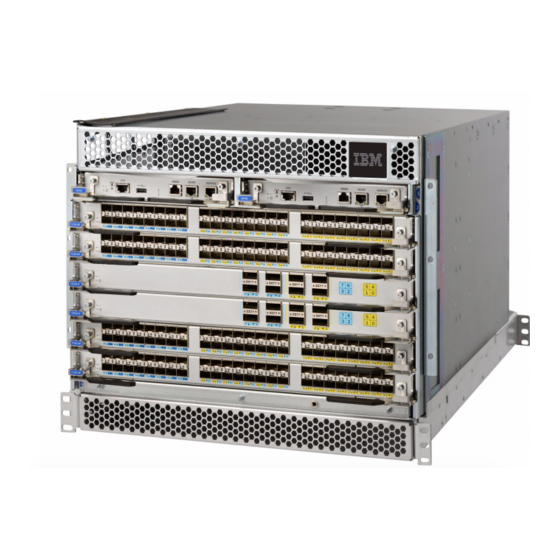
Port-side view of device The following illustration shows the port-side view of the SAN256B-6 Director with installed blades identified. Note that an SX6 extension blades are not shown in the following illustration, but would install in the same slots as the FC32-48 or FC32-64 port blades. -
Page 32: Port-Side Slot Numbering
Port-side slot numbering The SAN256B-6 contains 6 full-width slots and two half-width slots, for a total of 8 slots. Facing the port side of the device, the half-width slots are on the top, numbered 1 and 2 from left to right. The remaining full-width slots are numbered 3 through 8, counting from top to bottom of chassis. -
Page 33: Nonport Side Of The San256B-6
Figure 2. Nonport side of the SAN256B-6 (sample configuration) 1 - WWN bezel (WWN cards behind) 2 - Power supply assembly 3 - Fan assembly 4 - 2AWG Panduit LCD2-14AF lug for building ground connection Depending on fans and power supplies installed, airflow can be from the port side to the nonport side or the nonport side to the port side of the chassis through the side air vent. - Page 34 SAN256B-6 Installation, Service, and User Guide...
-
Page 35: Preparing For The Installation
Make sure the airflow around the front, sides, and back of the device is not restricted. CAUTION: To protect the serial port from damage, keep the cover on the port when not in use. CAUTION: Never leave tools inside the chassis. © Copyright IBM Corp. 2018... - Page 36 Use safe lifting practices when moving the product. 18-32 kg (39.7-70.5 lbs) CAUTION: A fully populated chassis weighs approximately 145.83 kg (321.5 lbs) and requires a hydraulic or assisted lift to install it. 18-32 kg (39.7-70.5 lbs) SAN256B-6 Installation, Service, and User Guide...
-
Page 37: Facility Requirements
Products. DANGER Use only optical transceivers that are qualified by IBM and comply with the FDA Class 1 radiation performance requirements defined in 21 CFR Subchapter I, and with IEC 825 and EN60825. Optical products that do not comply with these standards might emit light that is hazardous to the eyes. -
Page 38: Time And Items Required For Installation
As a standalone unit on a flat surface. v In a 19-inch Electronic Industries Association (EIA) rack or in a telecommunications (Telco) rack using a rack mount kit. Refer to“Mounting options” on page 15 for applicable rack mount kits. SAN256B-6 Installation, Service, and User Guide... -
Page 39: Quick Installation Checklists
The following table describes the main installation and setup tasks, the estimated time required for each, and the items required to complete the task for a device that is fully populated with port blades. Configurations with fewer blades or ports require less time. These time estimates assume a prepared installation site and appropriate power and network connectivity. -
Page 40: Installation And Basic System Configuration
The power supplies and fan trays are clearly labeled with either a green arrow with an "E", or an orange arrow with an "I." For more details, refer to “Fan and power supply airflow” on page 162. SAN256B-6 Installation, Service, and User Guide... - Page 41 Establish an Ethernet connection By establishing an Ethernet connection, you can complete the device configuration using a serial session, Telnet, or management application, such as IBM Network Advisor. Refer to“Establishing an Ethernet connection to the device” on page 55. Optional: Configure the DNS Use the dnsconfig command to create DNS server entries.
-
Page 42: Items Shipped
Save shipping cartons and packaging in the event you need to return the device. Packaged in device shipping carton: v SAN256B-6 switch with shipping tray v Packing foam v Antistatic plastic v Inner foam Packaged in device shipping carton or separate carton. -
Page 43: Mounting The Device
18 for instructions. v In a two-post Telco rack: – Use the mid-mount rack kit for SAN256B-6 for two-post racks . – Refer to “Installing the 8U Chassis Mid-Mount Rack Kit for Two-Post Racks” on page 33 for instructions. - Page 44 18-32 kg (39.7-70.5 lbs) CAUTION: You can connect the device to building ground by connecting an appropriate 2 AWG wire from a grounded connection to the 2AWG Panduit LCD2-14AF lug on the nonport-side of the device. SAN256B-6 Installation, Service, and User Guide...
-
Page 45: Unpacking And Transporting The Device
Unpacking and transporting the device About this task Use the following procedure to unpack and install your device. DANGER A fully populated chassis weighs approximately 68.95 kg (152.0 lbs) and requires a hydraulic or assisted lift to install it. If a lift tool is not available, the director chassis must be depopulated completely before installing it into the rack. -
Page 46: Installing The 8U Chassis Airflow Diversion Or Port Side Exhaust Kit For Four-Post Racks
For SAN256B-6, if nonport-side exhaust (NPE) fan and power supply assemblies are installed, air flows through the side vent and exhausts to the nonport side of the chassis. When nonport-side intake (NPI) fan and power supply assemblies are installed, air flows from the nonport-side and exhausts through the side vent. -
Page 47: Parts List
Parts list The following parts list refers to items illustrated in the following figure. Note: Not all parts may be used with certain installations depending on the device type. Table 8. Hardware for Airflow Diversion and Port-Side Exhaust Kit for 18-24 in. (45.72 to 60.96 cm) racks Description Quantity Top rail... -
Page 48: Airflow Diversion And Port-Side Exhaust Kit Assembly For 18-24 In. (45.72 To 60.96 Cm) Racks
8 - Alignment washer for racks that have rails with square holes 9 - 6-32 x .25 in. (.635 cm) Phillips screw 10 - Top rail mounting brackets for 18-20 in., (45.72-50.8 cm) 20-22-in. (50.8-55.88 cm), and 22-24.in (55.88-60.96 cm) racks 11 - Shelf saddle SAN256B-6 Installation, Service, and User Guide... -
Page 49: Torque Requirements
Torque requirements Use the following torque settings when tightening screws that secure the rack mount kit and device to the rack. Table 9. Torque requirements for mounting screws Screw size Torque 6-32 x .25 in. (.635 cm) Phillips screw 8.75 in-lb (10 cm-kg) 10-32 x .63 in.(1.60 cm) Phillips screw 32 in-lb (36.86 cm-kg) Assembling the rack hardware... - Page 50 4. Place the shelf (refer to the following figure) on the saddle then secure it to the rack rails using four 10-32 screws with washers (refer to Figure 7). Tighten the screws according to specifications under “Torque requirements” on page 21. SAN256B-6 Installation, Service, and User Guide...
-
Page 51: Shelf Installed In Rack
Figure 6. Shelf installed in rack 1 - Shelf 2 - 10-32 x .63 in.(1.60 cm) Phillips screw with washers Note: For rails with round holes, use the clip nuts on the front rails for securing 10-32 screws. For rails with square holes, use the retainer nuts. 5. -
Page 52: Installing Air Duct Into Side Slot On Shelf
For rails with square holes, use the two standard 10-32 screws with blue Loctite on the threads and alignment washers (refer to Figure 7) on each end of the top rail assembly. Tighten the screws according to specifications under “Torque requirements” on page 21. SAN256B-6 Installation, Service, and User Guide... -
Page 53: Installing The Device In The Rack
Figure 8. Securing top rail in rack 1 - Top rail 2 - Duct 3 - 6-32 x .25 in. (.635 cm) Phillips screws 4 - 10-32 x .5 in. (1.27 cm) Phillips screws with blue Loctite on threads and alignment washers or 10-32 x .63 in.(1.60 cm) Phillips screw with square cone washer Installing the device in the rack Procedure... -
Page 54: Installing The Device In A 27-31-Inch Rack
Figure 9. IBM device with 18-24 in. (45.72 to 60.96 cm) kit installed in rack 1 - 10-32 x .63 in.(1.60 cm) Phillips screw with square cone washer for racks that have rails with round holes Note: For rails with round holes, use the clip nuts on the front rails for securing 10-32 screws. -
Page 55: Airflow Diversion And Port-Side Exhaust Kit Assembly For 27-31 In. (68.58 To 78.74 Cm) Racks
Table 10. Hardware for Airflow Diversion and Port Side Exhaust Kit for 27-31 in. (68.58 to 78.74 cm) racks (continued) Description Quantity Shelf 10-32 x .5 in. (1.27 cm) Phillips screw (blue Loctite on threads) 10-32 x .63 in.(1.60 cm) Phillips screw with square cone washer 10-32 clip nut for racks that have rails with round holes 10-32 retainer nut for racks that have rails with square holes Alignment washer for racks that have rails with square holes... -
Page 56: Torque Requirements
Note that the following figure shows relative positions for these nuts in the rack rails to mount the shelf and device. You may mount the shelf and device in 9U of rack space higher or lower in the rack than shown. SAN256B-6 Installation, Service, and User Guide... -
Page 57: Clip And Retainer Nut Locations On Rack Rails
Figure 11. Clip and retainer nut locations on rack rails 1 - Attaching clip nuts for round hole rails 2 - Clip or retainer nut locations for device 3 - Clip or retainer nut locations for shelf 4 - Retainer nut for rails with square holes 5 - Rail 3. -
Page 58: Shelf Installed In Rack
Insert the top rail assembly down into the air duct assembly and then secure the top rail assembly to the air duct assembly with two 6-32 screws, one screw on each side of the air duct assembly. SAN256B-6 Installation, Service, and User Guide... -
Page 59: Securing Top Rail In Rack
Tighten the screws according to specifications under“Torque requirements” on page 21. Figure 14. Securing top rail in rack 1 - Top rail assembly 2 - Air duct assembly 3 - 6-32 x .25 in. (.635 cm) Phillips screw 4 - 10-32 x .5 in. (1.27 cm) Phillips screw with blue Loctite on threads or 10-32 x .63 in.(1.60 cm) Phillips screw with square cone washer for racks that have rails with round holes 6. -
Page 60: Installing The Device In The Rack
.63 in.(1.60 cm) Phillips screw with square cone washer for racks that have rails with round holes. Use either 10-32 retainer nut for racks that have rails with square holes or 10-32 clip nut for racks that have rails with round holes to retain screws. SAN256B-6 Installation, Service, and User Guide... -
Page 61: Installing The 8U Chassis Mid-Mount Rack Kit For Two-Post Racks
The following parts are provided with the 8U Chassis Mid-Mount Rack Kit for Two-Post Racks. Note: Not all parts may be used with certain installations depending on the device being installed. Use parts in the following rack mount kit to install the IBM SAN256B-6 in a two-post rack. Mounting the Device... -
Page 62: Assembling The Rack Hardware
2. Install the saddle to the equipment rack rails using the following steps while referring to the following figure. Also refer to Figure 18 on page 36 for details on securing screws to equipment rack. SAN256B-6 Installation, Service, and User Guide... -
Page 63: Saddle Installed In A Rack
a. Install the saddle to the port side of the rack rails using four 10-32 screws with square-cone washers, two screws on each side of the saddle. Tighten the screws to 32 in-lb (36.86 cm-kg). b. Move the mid-mount brackets into position so they align with the rack mounting holes on the nonport side of the rack. -
Page 64: Using Clip Nuts And Retainer Nuts To Secure
3. Remove any existing rack-mount brackets from the device, and install the new Telco mid-mount brackets from the accessory kit. Refer to the following figure. Figure 19. Telco mid-mount brackets installation 1 - Telco mid-mount mounting brackets (left and right) SAN256B-6 Installation, Service, and User Guide... -
Page 65: Installing The Device In The Rack
Installing the device in the rack About this task DANGER Use safe lifting practices when moving the product. 18-32 kg (39.7-70.5 lbs) Procedure 1. Ensure that the door is removed from the port side of the device, if installed. Refer to procedures for removing and replacing the device door in this guide. -
Page 66: Installing The 8U Chassis 27-31-Inch Rail Rack Kit For Four-Post Racks
Torque wrench with #2 Phillips screwdriver tip v Flathead screwdriver v Hydraulic or assisted lift with a minimum raise of 140 cm (55 in.) and a minimum capacity of 113 kg (250 lbs). SAN256B-6 Installation, Service, and User Guide... -
Page 67: Parts List
DANGER If a lift tool is not available, the director chassis must be depopulated completely before installing it into the rack. Remove the power supplies, fan modules, all of the blades, the cable management fingers, and the chassis door (if equipped). Install the empty chassis into the rack following the chassis installation instructions. -
Page 68: Assembling The Rack Hardware
Note: For rails with round holes, use the clip nuts on the rack rails for securing 10-32 x .63 screws. For rails with square holes, use the retainer nuts. Refer to the following figure. SAN256B-6 Installation, Service, and User Guide... -
Page 69: Installing The Device In The Rack
Figure 24. Using clip nuts and retainer nuts to secure screws to rack rails 1 - Clip nuts 2 - Round hole rack rail 3 - Retainer nut 4 - Square hole rack rail Installing the device in the rack Procedure 1. -
Page 70: Removing The Protective Cover
The chassis can overheat if air vents are blocked with this cover. Remove this cover by removing the Phillips screws securing it to the mounting bracket on each side of the chassis. SAN256B-6 Installation, Service, and User Guide... -
Page 71: Removing Protective Cover From San256B-6
Figure 27. Removing protective cover from SAN256B-6 Note: Do not attempt to lift or support the chassis by the protective cover. Mounting the Device... - Page 72 SAN256B-6 Installation, Service, and User Guide...
-
Page 73: Initial Setup And Verification
Set a unique domain ID for the device. Disable the device using the switchDisable command, and then use the configure command to step through prompts to configure a domain ID. Use switchEnable to re-enable the device. © Copyright IBM Corp. 2018... -
Page 74: Items Required
Access to an FTP server or USB device for backing up (uploading) or downloading the device configuration or collecting supportsave output data (optional). v A USB drive for collecting supportsave output data (optional) Providing power to the device Before you begin Before connecting power, refer the following. SAN256B-6 Installation, Service, and User Guide... -
Page 75: Connecting Power Cord To Ac Power Supplies
v Electrical caution and danger statements in “Safety precautions” on page 7 and “Facility requirements” on page 9 v Power supply specifications section in the Appendix B, “Product Specifications,” on page 231 for power supply requirements of your device. About this task Perform the steps to provide power that are applicable to your power supply model. -
Page 76: Connecting Power Cord To Hvac/Hvdc Power Supplies
2AWG Panduit LCD2-14AF lug located to the left of the bottom fan assembly near the bottom of the chassis. 3. Remove the protective cover if it is still installed over the top air vents on the port side of the chassis. SAN256B-6 Installation, Service, and User Guide... - Page 77 CAUTION: Remove the protective cover on the port side of chassis before applying power. This cover is attached over the air vents. If not removed, the chassis can overheat and will eventually shut down. 4. Install all power supplies provided for your device if not already installed. Refer to “Installing a power supply”...
- Page 78 Make sure that AC power plug is attached to the power-source end of the HVAC/HVDC power cord that meets your facility and local code requirements. For more information on the HVAC/HVDC power cord available for these power supplies, refer to “Using HVAC/HVDC power cords” on page 51. SAN256B-6 Installation, Service, and User Guide...
-
Page 79: Using Hvac/Hvdc Power Cords
DANGER Make sure that the power source circuits are properly grounded, then use the power cord supplied with the device to connect it to the power source. c. If connecting to an AC power source, connect to a power source with voltage of 200–277 VAC, 50/60 Hz (recommended). - Page 80 Note that the connector's latch should be positioned under the connector and will latch when the power cord connector is fully inserted into the power supply. 1. Connector latch Power cable SAN256B-6 Installation, Service, and User Guide...
-
Page 81: Establishing A Serial Connection To The Device
Establishing a serial connection to the device About this task To establish a serial connection to the console port on the device, complete the following steps. Procedure 1. Verify that the device is powered on and that POST is complete by verifying that all power LED indicators on the power supplies, fans, and blades display a steady green light. -
Page 82: Configuring The Ip Addresses
2. Configure the chassis management IP address by entering the ipaddrset -chassis command: swDir:admin> ipAddrSet -chassis Enter required information at the prompts. Specify the -chassis IP address. The -sw 0 IP address is not valid on this device. SAN256B-6 Installation, Service, and User Guide... -
Page 83: Establishing An Ethernet Connection To The Device
Note: Connecting the CP blades to a private network or VLAN is recommended. After establishing an Ethernet connection, you can complete the device configuration using a serial console connection, Telnet connection, or management applications, such as Web Tools or IBM Network Advisor. -
Page 84: Setting The Domain Id
You can synchronize the local time of the principal or primary fabric configuration server (FCS) device to that of an external Network Time Protocol (NTP) server. Perform the following steps to set the date and time. Procedure 1. Log into the device using one of the following methods: SAN256B-6 Installation, Service, and User Guide... -
Page 85: Setting The Time Zone
v A serial console connection to the active CP blade. The active CP is indicated by an illuminated blue LED on the blade front panel. v A Telnet session using the chassis management IP address. 2. Log into the device using admin. If you have not changed the default password, usepassword. 3. -
Page 86: Synchronizing Local Time With An External Source
The ipaddr variable represents the IP address of the NTP server that the device can access. This argument is optional; by default, the value is "LOCL". switch:admin> tsclockserver 192.168.126.60 Updating Clock Server configuration...done. Updated with the NTP servers SAN256B-6 Installation, Service, and User Guide... -
Page 87: Customizing The Chassis And Switch Name
Customizing the chassis and switch name About this task The switch name of the device can be up to 31 characters long and must begin with a letter. It can include letters, numbers, hyphens, and underscore characters. The chassis name and switch name of the device can be up to 31 characters long; can include letters, numbers, hyphens, and underscore characters;... -
Page 88: Verifying Installed Licenses And License Key
4. Verify the correct operation of the device by entering the following commands. Copy the output to a file to save the information. Command Description Displays blades (with model numbers) detected in each slot slotshow -m SAN256B-6 Installation, Service, and User Guide... -
Page 89: Backing Up The Configuration
Command Description slotshow -p Displays power consumption data and enabled status for installed blades. Displays power supply status and information psShow fanShow Displays fans status and information Displays switch status and information switchShow fabricShow Displays information about the device operation in the fabric and general information about the fabric Displays the current status of each slot in the device slotShow... -
Page 90: Powering Down The Chassis
To disconnect power cables from HVAC/HVDC power supplies only, use the following steps. a. Remove the cable restraint cover, if installed under the power cord connector, by unscrewing the two torx head screws. 1. Torx head screws 2. Metal cable restraint cover SAN256B-6 Installation, Service, and User Guide... - Page 91 CAUTION: When removing the metal cable restraint cover under the high voltage power supply inlet, remove the two Torx head screws only. Disconnect the power cable from the power supply. Note that the latch for the power cable connector is positioned under the connector. Press on the latch using a small screwdriver or other tool to unlatch from the power supply.
- Page 92 SAN256B-6 Installation, Service, and User Guide...
-
Page 93: Installing Transceivers And Cables
40 GbE QSFP+ for bidirectional SR Fixed 40 GbE connectivity with LC connectors 100 GbE QSFP28 for SR4 Fixed 4x25 GbE (breakout connectivity over MTP 1x12 cabling mode) This QSFP+ provides 4x25 GbE connectivity only. © Copyright IBM Corp. 2018... - Page 94 The following notes apply to QSFP transceivers on core routing blades. v To connect an ICL between a QSFP on a SAN256B-6 and SAN512B-6 Director core routing blade and a QSFP on a DCX 8510 Director core routing blade, use the 4x32 Gbps QSFP28 SWL transceiver that supports 4x32 Gbps and 4x16 Gbps breakout operation.
-
Page 95: Port And Extension Blade Transceivers
2. SFP connectors DANGER Use only optical transceivers that are qualified by IBM and comply with the FDA Class 1 radiation performance requirements defined in 21 CFR Supchapter I, and with IEC 60825 and EN60825. Optical products that do not comply with these standards might emit light that is hazardous to the eyes. -
Page 96: Fc Sfp+ Transceiver
The following illustrates a 40 GbE QSFP transceiver that uses a bail latching mechanism to release the transceiver from the blade port cage. A separate fiber optic cable connects to the transceiver. Some QSFP transceivers have an integrated pull tab that releases the transceiver from the port. SAN256B-6 Installation, Service, and User Guide... -
Page 97: Core Routing Blades
Core routing blades QSFPs installed in core routing blades are used for connecting inter-switch links (ICLs) between SAN256B-6 and SAN512B-6 Directors or between SAN256B-6, SAN512B-6, SAN384B-2, and SAN768B-2 Directors. Interconnecting these devices increases the number of useable ports for device connections. -
Page 98: 4X16 Gbps 2 Km Lwl Qsfp
4x32 Gbps and 4x16 Gbps speeds so can be used for an ICL connection between a 32 Gbps QSFP on a SAN256B-6 and SAN512B-6 Director core routing blade and a 16 Gbps QSFP transceiver on SAN384B-2 and SAN768B-2 Director core routing blade. Use the appropriate ICL kit for this application. -
Page 99: 4X32 Gbps 2 Km Lwl Qsfps
The installation or replacement procedure for one transceiver takes less than 5 minutes. Ensure that the following items are available: v Required number of compatible power cables v Required number of supported IBM-branded transceivers v Required number of compatible fiber-optic cables v Optical transceiver extraction tool (for 10 Gbps transceiver only) -
Page 100: Precautions Specific To Transceivers And Cables
All fiber-optic interfaces use Class 1 lasers. CAUTION: Use only optical transceivers that are qualified by IBM and comply with the FDA Class 1 radiation performance requirements defined in 21 CFR Subchapter I, and with IEC 825 and EN60825. Optical products that do not comply with these standards might emit light that is hazardous to the eyes. -
Page 101: Cable Management
Installing an SFP+ transceiver About this task The device supports only IBM-qualified transceivers. If you use an unqualified transceiver, the switchshow command output shows the port in a Mod_Inv state. Fabric OS also logs the issue in the system error log. To insert an SFP+ transceiver, complete the following steps: Note: Always use the pull tab to insert or remove 16 Gbps and 32 Gbps transceivers as they might be hot. -
Page 102: Installing An Sfp+ Transceiver With Pull Tab
Do not insert any unsupported cable intended for an other type of transceiver into a regular SFP+ transceiver. You may damage the cable as well as the transceiver. SAN256B-6 Installation, Service, and User Guide... -
Page 103: Replacing An Sfp+ Transceiver
Replacing an SFP+ transceiver About this task Complete the following steps to remove and then install a new SFP+ transceiver. Note: The 16- and 32-Gbps SFP+ transceivers do not have bails but pull tabs. Always use the pull tab to insert or remove the SFP+ transceivers, as the transceiver might be hot. -
Page 104: Installing A Qsfp Transceiver
Installing a QSFP transceiver About this task The device supports only IBM-qualified transceivers. If you use an unqualified transceiver, the switchshow command output shows the port in a Mod_Inv state. Fabric OS also logs the issue in the system error log. Also note the following: v Each QSFP contains four individual 16 Gbps or 32 Gbps ports. -
Page 105: Replacing A Qsfp Transceiver
Replacing a QSFP transceiver About this task The device supports only IBM-qualified transceivers. If you use an unqualified transceiver, the switchshow command output shows the port in a Mod_Inv state. Fabric OS also logs the issue in the system error log. Also note the following: v Each QSFP contains four individual 16 Gbps or 32 Gbps ports. -
Page 106: Verifying The Operation Of New Transceivers
Verifying the operation of new transceivers About this task You can use the following commands to verify if the transceivers are working correctly: v sfpShow v switchShow v switchshow-slot slot, where slot is slot number v switchshow -qsfp SAN256B-6 Installation, Service, and User Guide... - Page 107 v errDump v fabricShow Example For output examples and additional information on Fabric OS commands, refer to “Using monitoring commands” on page 97 and the Fabric OS Command Reference. For more information about error messages, refer to the Fabric OS Message Reference. Installing Transceivers and Cables...
- Page 108 SAN256B-6 Installation, Service, and User Guide...
-
Page 109: Monitoring The Device
1. Blade power LED 2. Blade status LED 3. Status LED for upper FC port 4. Status LED for lower FC port The following table describes the port blade LED patterns and the recommended actions for those patterns. © Copyright IBM Corp. 2018... -
Page 110: Port Blade Led Descriptions
2 seconds) or is faulty. reseat it. If LED continues to flash, replace the blade. Fast-flashing amber (on 1/2 Environmental range Check for out-of-bounds second, then off 1/2 exceeded. environmental condition second) and correct it. SAN256B-6 Installation, Service, and User Guide... -
Page 111: Interpreting Fc32-64 Port Blade Leds
Table 16. Port blade LED descriptions (continued) | | | | LED purpose Color Status Recommended action | | | FC port Status No light (LED is off) Port has no incoming Verify that the power LED power, or there is no light is on, check the transceiver or signal carrier detected. -
Page 112: Fc32-64 Port Blade Leds
No light (LED is off) Blade is not powered on. Ensure that the blade is Power firmly seated, with ejectors pushed in fully to center of blade and captive screw for each ejector fully tightened. SAN256B-6 Installation, Service, and User Guide... - Page 113 Table 17. Port blade LED descriptions (continued) | | | | LED purpose Color Status Recommended action No light (LED is off) Blade is either healthy or Verify that the power LED does not have power. is on. Status | | | Steady amber Blade is faulty.
-
Page 114: Interpreting Extension Blade Leds
No light (LED is off) Blade is not powered on. Ensure that the blade is Power firmly seated, with ejectors pushed in fully to center of blade and captive screw for each ejector fully tightened. SAN256B-6 Installation, Service, and User Guide... - Page 115 Table 18. Extension blade LED descriptions (continued) LED purpose Color Status Recommended action No light (LED is off) Blade is either healthy or Verify that the power LED does not have power. is on. Status Steady amber Blade is faulty or Ensure that the blade is initializing.
-
Page 116: Interpreting Control Processor Blade Leds
Interpreting control processor blade LEDs Refer to the following illustration and table to interpret the LED patterns on the CPX6 blade. The LED patterns may temporarily change during POST and other diagnostic tests. SAN256B-6 Installation, Service, and User Guide... -
Page 117: Cp Blade Led Descriptions
Figure 47. Control processor blade (CPX6) 1 - Blade status LED 2 - Blade power LED 3 - Chassis beacon LED 4 - Active (blue) CP LED 5 - 10/100/1000 Mb/s Ethernet port (MGMT) link status LED 6 - 10/100/1000 Mb/s Ethernet port (MGMT) link activity LED 7 - 10/100/1000 Mb/s Ethernet port (SERVICE) link status LED 8 - 10/100/1000 Mb/s Ethernet port (SERVICE) link activity LED Note: The 10 Gbps Base-T RJ45 Ethernet port, shown below the blade beacon LED, is reserved for future... -
Page 118: Interpreting Core Routing Blade Leds
No action required. Interpreting core routing blade LEDs Refer to the following illustration and table to interpret the LED patterns on the CR32-8 blade. The LED patterns may temporarily change during POST and other diagnostic tests. SAN256B-6 Installation, Service, and User Guide... -
Page 119: Cr32-4 Core Routing Blade Leds
Figure 48. CR32-4 core routing blade LEDs 1 - Blade power LED 2 - Blade status LED 3 - Status LED for lower QSFP port 4 - Status LED for top QSFP port Table 20. Core routing blade LED descriptions LED purpose Color Status... -
Page 120: Interpreting Wwn Card Leds
Card is not receiving Ensure that device power power. supplies are firmly seated, Power power cables are connected, and that cables are connected to power source. Steady green Card is receiving power. No action required. SAN256B-6 Installation, Service, and User Guide... -
Page 121: Interpreting Power Supply Leds
Interpreting power supply LEDs Refer to the following illustration and table to interpret the LED patterns on the power supply. The LED patterns may temporarily change during POST and other diagnostic tests. The SAN256B-6 has two power supplies. Figure 50. 2870 W AC Power supply LED... - Page 122 5 seconds. distribution unit (PDU) or system providing power to power supply assembly. Check cabling and voltage between PDU and switch. Correct the voltage as necessary. If correct voltage is verified, replace power supply assembly. SAN256B-6 Installation, Service, and User Guide...
-
Page 123: Interpreting Fan Assembly Leds
Interpreting fan assembly LEDs Refer to the following illustration and table to interpret the LED patterns on fan assemblies. The LED patterns may temporarily change during POST and other diagnostic tests. The SAN256B-6 has two fan assemblies. Figure 51. Fan assembly LEDs... -
Page 124: Interpreting Post And Boot Results
Any errors detected during POST are written to the system log, which is accessible through the errShow command. For information about error messages, refer to the Fabric OS Message Reference. POST includes the following steps: SAN256B-6 Installation, Service, and User Guide... -
Page 125: Boot
Procedure 1. Preliminary POST diagnostics are run. 2. Operating system is initialized. 3. Hardware is initialized. 4. Diagnostic tests are run on several functions, including circuitry, port functionality, ability to send and receive frames, all aspects of memory, parity, statistics counters, and serialization. Boot About this task In addition to POST, boot includes the following steps after POST is complete:... - Page 126 Factory Serial Num: DYK0338L00E Manufacture: Day: 7 Month: 10 Year: 2015 Update: Day: 23 Month: 3 Year: 2016 Time Alive: 87 days Time Awake: 0 days CORE BLADE Slot: 5 Header Version: Power Consume Factor: -450W SAN256B-6 Installation, Service, and User Guide...
- Page 127 Power Usage: -264W Factory Part Num: 60-1003199-08 Factory Serial Num: DYH0344L005 Manufacture: Day: 17 Month: 11 Year: 2015 Update: Day: 0 Month: 0 Year: 0 Time Alive: 0 days Time Awake: 0 days CORE BLADE Slot: 6 Header Version: Power Consume Factor: -450W Power Usage: -289W...
-
Page 128: Errdump And Errshow
2016/03/28-08:44:28,[FV-1001], 90, SLOT 1 CHASSIS,INFO,My_Switch,Flow Vision daemon initialized. 2016/03/28-08:44:51,[FSSM-1002],91,SLOT 1 CHASSIS,INFO,My_Chassis,HA State is in sync. 2016/03/28-08:44:51,[SULB-1003],92,SLOT 1 CHASSIS,INFO,My_Chassis,Firmwarecommit has started. 2016/03/28-08:48:27,[SULB-1004],93,SLOT 1 CHASSIS,INFO,My_Chassis,Firmwarecommit has completed. 2016/03/28-08:48:27,[SULB-1036],94,SLOT 1 CHASSIS,INFO,My_Chassis,The new Version: Fabric OS v8.0.1_bld52. SAN256B-6 Installation, Service, and User Guide... -
Page 129: Fanshow
2016/03/28-08:48:27,[SULB-1002],95,SLOT 1 CHASSIS,INFO,My_Chassis,Firmwaredownload command completed successfully. 2016/03/28-08:50:51,[IPAD-1003],96,SLOT 1 CHASSIS,INFO,My_Chassis,DNS parameters saved successfully. ------------------------------------------------------------------------------------------------------------- Note the following about this output: v The output can contain several thousand lines. Use errClear command to reset the output when needed. This command clears all error log messages for all director instances on the CP where the command is issued. -
Page 130: Psshow
Use this command to display the current temperature, fan, and power supply status, and readings from sensors located on the device. The sensorShow command output is similar to tempShow except that fan and power supply sensor information is also included. Temperatures are in Celsius only. SAN256B-6 Installation, Service, and User Guide... -
Page 131: Slotshow
Use this command to display the current status of each blade in the system. Depending on the option used, the command retrieves information on blade type, blade ID, status, IBM model name, and power usage for each slot in the switch or chassis. Use the -m operand to display the blade model name and status. - Page 132 Slot 3/Port 0: id (sw) Vendor: IBM Serial No: JAF3154200000VJ Speed: 8,16,32_Gbps Slot 3/Port 1: -- Slot 3/Port 2: -- Slot 3/Port 3: -- Slot 3/Port 4: -- Slot 3/Port 5: -- Slot 3/Port 6: -- Slot 3/Port 7: --...
- Page 133 Slot 7/Port 27: -- Slot 7/Port 28: -- Slot 7/Port 29: -- Slot 7/Port 30: -- Slot 7/Port 31: id (sw) Vendor: IBM Serial No: JAF3154200000K8 Speed: 8,16,32_Gbps Slot 7/Port 32: -- Slot 7/Port 33: -- Slot 7/Port 34: id (sw) Vendor: IBM...
- Page 134 Slot 8/Port 13: -- Slot 8/Port 14: -- Slot 8/Port 15: id (sw) Vendor: IBM Serial No: JAF315420000188 Speed: 8,16,32_Gbps Slot 8/Port 16: -- Slot 8/Port 17: -- Slot 8/Port 18: -- Slot 8/Port 19: -- Slot 8/Port 20: --...
-
Page 135: Switchshow
Slot 5/Port 24: -- Slot 5/Port 25: -- Slot 5/Port 26: -- Slot 5/Port 27: -- Slot 5/Port 28: id 7/0 (sw) Vendor: IBM Serial No: ZTA11539000002A Speed: 32_Gbps Slot 5/Port 29: id 7/1 (sw) Vendor: IBM Serial No: ZTA11539000002A Speed: 32_Gbps... -
Page 136: Supportsave
FTP, SCP, or SFTP parameters set bysupportFtp. The-n operand turns off confirmation prompting. chassis:admin> supportsave -n -c Saving support information for switch:ras010, module:RAS................Saving support information for switch:ras010, module:FTRACE_START..Saving support information for switch:ras010, module:SSHOW_SYS..........SAN256B-6 Installation, Service, and User Guide... - Page 137 Saving support information for switch:ras010, module:SSHOW_ISWITCH........Saving support information for switch:ras010, module:FABRIC....Saving support information for switch:ras010, module:DIAG....Saving support information for switch:ras010, module:RTE... Saving support information for switch:ras010, module:IF_TREE... Saving support information for switch:ras010, module:ISCSID_DBG... Saving support information for switch:ras010, module:AGDUMP... Saving support information for switch:ras010, module:AGWWNS...
-
Page 138: Tempshow
Use this command to display temperature readings of blade temperature sensors. The command displays the following information: v Sensor ID (an index number) v Slot number v Sensor index (when command issued with the--detail option) v Sensor state (OK or absent) SAN256B-6 Installation, Service, and User Guide... -
Page 139: Running Diagnostic Tests
v Temperature in both Centigrade and Fahrenheit Following is an example of tempShow output. chassis:admin> tempshow Sensor Slot Sensor State Centigrade Fahrenheit Index =================================================================== Note the following about this output: v The absent state simply reflects that the blade slot is empty. v The sensor index is mainly for support use. - Page 140 For more information about diagnostic tests and how to run them, refer to the Fabric OS Administrator's Guide and the Fabric OS Command Reference. For information about system error messages (errShow or errDump), refer to the Fabric OS Troubleshooting and Diagnostics Guide. SAN256B-6 Installation, Service, and User Guide...
-
Page 141: Port And Extension Blades
Bicolor green/amber FC port status LEDs For details on interpreting LED operation, refer to “Interpreting FC32-48 port blade LEDs” on page 81. FC32-48 port blade numbering and trunking The following illustration shows how ports are numbered on the blade. © Copyright IBM Corp. 2018... -
Page 142: Fc32-64 Port Blade Overview
Connection speeds depend on the QSFP transceiver installed. For example, a 4x32 Gbps QSFP+ transceiver would provide four 32/16 Gbps connections and a 4x16 Gbps QSFP+ transceiver provides four 16/8/4 Gbps connections. SAN256B-6 Installation, Service, and User Guide... -
Page 143: Fc32-64 Port Blade Numbering And Trunking
5 and 6. Up to four hot-swappable port blades can be installed in a single chassis to provide up to 192 32 Gbps FC ports. v It is recommended that at least two fan assemblies be installed the SAN256B-6 if FC32-64 blades are being used. -
Page 144: Extension Blade Overview
Fibre Channel or IP connections. Extension tunnels, built on a physical connection between two extension switches or blades, allow Fibre Channel and IP I/O to pass through the IP WAN. The SX6 Extension blade can connect with an SX6 blade in another SAN256B-6 or with a 7840 Extension Switch. -
Page 145: Extension Features
32 Gbps, 16 Gbps transceivers operating at 4, 8, or 16 Gbps, and 10 Gbps transceivers operating at fixed 10 Gbps. FC ports can autonegotiate speeds with connecting ports. v 16 10 or 1 GbE SFP+ and two 40 GbE QSFP ports. These ports allow connection of blades to IP WANs and allow Fibre Channel and IP I/O to pass through the IP WAN using extension tunnels. -
Page 146: Sx6 Blade Port Numbering And Trunking
M-EOS or third-party switches. v There must be a direct connection between participating switches. For full details on trunking requirements and configuration, refer to theFabric OS Administrator's Guide. SAN256B-6 Installation, Service, and User Guide... -
Page 147: Precautions Specific To The Blade
This topic describes how to remove and replace a port or extension blade. Observe the following precautions when replacing these blades: v The SX6 extension and FC32-48 port blade can only be installed in SAN512B-6 and SAN256B-6 switches. v Wear an appropriately grounded ESD wrist strap when handling and installing device blades and cards. -
Page 148: Time And Items Required For Removal And Installation
Delete all IP interfaces (IPIFs) defined on the blade using the portcfg ipif slot/geX delete command. d. If logical switches are used on the switch, move all blade ports back to the default logical switch. Refer to the lscfg command in the Fabric OS Command Reference for details. SAN256B-6 Installation, Service, and User Guide... -
Page 149: Removing And Replacing Port Or Extension
Note: If you are removing the extension blade to install in a different slot, you must remove configuration using the preceding steps, then reconfigure the blade in the new slot. If you move the blade without performing these steps and the blade faults, you must move the blade to the original slot and remove configuration. -
Page 150: Installing A Blade
7. Group and route the cables through the vertical cable management finger assemblies. 8. Replace the chassis door. The door is required to meet EMI compliance. Verifying blade operation About this task Perform the following tasks to verify operation of blade: SAN256B-6 Installation, Service, and User Guide... - Page 151 2. Enter the following commands and note any error conditions: v slotshow -p - Displays the current data on each slot in the system, including blade type, blade ID, status, and IBM model name. v tempShow - Displays temperature reading of blades.
- Page 152 SAN256B-6 Installation, Service, and User Guide...
-
Page 153: Core Routing Blades
1 - QSFP ports 4-7 (right to left) 2 - QSFP ports 0-3 (right to left) 3 - Map of ports 2, 3, 6, and 7 4 - Map of ports 0, 1, 4, and 5 © Copyright IBM Corp. 2018... -
Page 154: Icl Trunking Groups
QSFPs within a trunk group on a core blade in another device using ICLs. Each CR32-4 blade on the SAN256B-6 has two ICL trunking groups consisting of the following QSFP ports:... -
Page 155: Icl Cabling Configurations
For more information recommended cabling topologies for ICLs, refer to “ICL cabling configurations.” Note: You cannot configure ISLs using ports on port blades and QSFP-based ICLs using ports on core routing blades concurrently on the same chassis. ISLs and ICLs can co-exist between a pair of chassis if the ISLs and ICLs are in different logical switches. - Page 156 Figure 57. ICL cable connections for SAN256B-6 and SAN512B-6 Director (sample configuration) To connect multiple SAN256B-6 and SAN512B-6 Directors via ICLs, a minimum of four ICL ports (two on each core routing blade) must be connected between each chassis. The dual connections on each core blade must reside within the same trunk group.
-
Page 157: Precautions Specific To The Blade
Figure 58. IBM SAN Director core-edge ICL topology SAN256B-6, SAN512B-6, SAN384B-2 and SAN768B-2 Directors can also be connected in a full-mesh configuration. For details on the following subjects, refer to the "Inter-Chassis Links' section of the Fabric OS Administration Guide:... -
Page 158: Faulty Core Routing Blade Indicators
Electrostatic discharge (ESD) grounding strap v Workstation computer v Replacement blade or filler panel v #1 Phillips screwdriver v QSFP transceivers (as needed) v Optical cables (as needed) SAN256B-6 Installation, Service, and User Guide... -
Page 159: Removing A Core Routing Blade
Note: For information about the transceivers that are qualified for this device, refer to “Installing Transceivers and Cables” on page 65. Removing a core routing blade About this task Complete the following steps to remove the core routing blade. Note: The device continues to operate while a core routing blade is being replaced. Procedure 1. -
Page 160: Installing A Core Routing Blade
When the blade face is about 2.54 cm (1 in.) from the chassis, you should feel resistance as the blade connectors meet the backplane connectors. c. Continue pushing with your thumbs or fingers until the ejectors move in towards the blade slightly indicating that the connectors are engaged. SAN256B-6 Installation, Service, and User Guide... -
Page 161: Verifying Blade Operation
d. Simultaneously push both ejector handles in towards the blade center with even pressure until the blade completely seats in the slot. Note: As you move the handles, you will hear connectors engaging the backplane connector and possibly a slight popping noise. This is normal and is due to the dense backplane. 4. - Page 162 SAN256B-6 Installation, Service, and User Guide...
-
Page 163: Control Processor Blades
Control processor blade overview The CPX6 control processor blades are half the slot height of other SAN256B-6 blades. Two CPX6 control processor blades are stacked vertically in the half slots on the left side of the chassis to provide CP redundancy. -
Page 164: Cpx6 Port Identification
CPX6 blades located in slots 1 and 2. Observe the following precautions when replacing these blades: v The CPX6 blade is compatible only with the SAN256B-6. v Wear an appropriately grounded ESD wrist strap when handling and installing blades and cards. -
Page 165: Blade Fault Indicators
CAUTION: Static electricity can damage the chassis and other electronic devices. To avoid damage, keep static-sensitive devices in their static-protective packages until you are ready to install them. CAUTION: Before plugging a cable into any port, be sure to discharge the voltage stored on the cable by touching the electrical contacts to ground surface. -
Page 166: Time And Items Required For Replacement
Enter the configupload -vf command, specifying a file name, when prompted, for saving configuration data. This saves the backbone virtual fabric data to the file name specified. For more information, refer to the Fabric OS Command Reference. SAN256B-6 Installation, Service, and User Guide... -
Page 167: Replacing A Cp Blade
c. In a FICON environment, log in as root and enter configupload --map to upload port-to-area mapping information. Specify a folder name, when prompted. This command saves the port-to-area addressing mode configuration files to the folder specified. Be sure to upload the configuration using the -map option for a FICON-enabled device if port-bound addressing is used. -
Page 168: Hot-Swap Procedure
As you slide out the blade, place one hand under blade for support. Be sure blade has cooled sufficiently to touch. CAUTION: To avoid damaging blade and chassis, do not push the blade into a slot or pull the blade from a slot using the ejector handles. SAN256B-6 Installation, Service, and User Guide... -
Page 169: Installing A Blade
Figure 61. Removal and replacement of the control processor blade (CPX6) 8. If the blade is not being replaced by another blade, install a filler panel and reinstall the chassis door. The filler panel is required for proper chassis cooling. The door is required to meet EMI compliance. Installing a blade About this task Note: Read all of the instructions for replacing the CP blade before beginning the procedure. -
Page 170: Verifying And Synchronizing Firmware On Blades
Run the firmwaresync command on the active CP blade to copy all firmware from the active CP blade to the standby CP blade. Note: Using this command requires that existing telnet, secure telnet, or SSH sessions to the standby CP blade to be restarted. SAN256B-6 Installation, Service, and User Guide... -
Page 171: Downloading Firmware From Ftp Server
v Run the firmwareDownload -s command or firmwaresync command (if versions are compatible) to update firmware on the replacement blade to bring it up to the proper level. 6. Perform one of the following tasks to download firmware: v If you are using an FTP server to download the firmware, skip to the procedure for downloading firmware from an FTP server. -
Page 172: Downloading Firmware From Usb Device
INIT: Sending processes the TERM signal Chassis_1:admin> HAMu Heartbeat down, stop FSS Unmounting all ##exiting due to signal: 9, pending signals: 0x20000, 0x0 ilesystems. Please stand by while rebooting the system... Restarting system. The system is coming up, please wait... SAN256B-6 Installation, Service, and User Guide... -
Page 173: Cold-Swap Procedure
Fri Jun 17 14:53:13 2016: Doing firmwarecommit now. Please wait ... Fri Jun 17 14:55:27 2016: Firmware commit completes successfully. Validating the filesystem ... Fri Jun 17 22:36:05 2016: Doing firmwarecommit now. Please wait ... Fri Jun 17 22:36:48 2016: Firmware commit completes successfully. 2016/06/17-14:56:50, [SULB-1004], 908, SLOT 2 | CHASSIS, INFO, ...Firmwarecommit has completed. -
Page 174: Installing A Blade
This is normal and is due to the dense backplane. 3. Tighten the captive for each ejector using a #1 Phillips screwdriver. Note: Be sure that captive screws are tightened. If not, high pressure from fan operation may unseat blade from chassis connectors. SAN256B-6 Installation, Service, and User Guide... -
Page 175: Completing The Replacement
4. Power up the device. 5. Connect the cables to the new CP blades. 6. Enter chassisDisable. 7. Enter configDownload -vf to download device virtual fabric data to the local system. The device reboots and partitions are restored. 8. Enter chassisDisable. 9. -
Page 176: Verifying Blade Operation
For output examples and additional information on Fabric OS commands, refer to “Using monitoring commands” on page 97 and the Fabric OS Command Reference. For more information about error messages, refer to the Fabric OS Message Reference. SAN256B-6 Installation, Service, and User Guide... -
Page 177: Wwn Cards
WWN card are located behind the WWN bezel on the nonport side of the device between the power supplies. The bezel must be removed to access the card trays. The following figure illustrates WWN card location and numbering. © Copyright IBM Corp. 2018... -
Page 178: Precautions Specific To Wwn Cards
WWN card fault indicators Before replacing a WWN card, verify that the replacement is necessary. Any of the following events can indicate that cards require replacement: SAN256B-6 Installation, Service, and User Guide... -
Page 179: Wwn Card Replacement Task Guide
v RASlog messages may occur during periodic WWN card audit routines alerting you of data or license mismatches between WWN cards and other errors. Some of these messages may direct you to contact technical support or to run the wwnrecover command. You can use this command to further verify or to fix problems. -
Page 180: Time And Items Required For Replacement
Mismatched data can be resolved, and corrupt data can sometimes be recovered. The following table lists RASlog messages that can occur during the WWN card audit routine. SAN256B-6 Installation, Service, and User Guide... -
Page 181: Preparing For Wwn Card Replacement
Table 29. RASlog messages from WWN card audit Error message Issue [EM-1220]...M1, ERROR ... A problem was found on one Some kind of error or mismatch has been detected in the or both CID cards (x), please run the wwnrecover tool to WWN card audit. -
Page 182: Hot-Swap Replacement
5. Contact IBM Support for replacement of WWN cards. IBM Support will request the partner or OEM to send WWN cards from FRU inventory to the nearest IBM Support office to be reprogrammed. IBM Support will require the Supportsave data taken in the previous step so that the replacement cards can be reprogrammed prior to shipping to the partner or your site. - Page 183 Procedure 1. Remove the defective WWN card assembly using procedures under “Removing the WWN card and bezel” on page 157. Removing a WWN card assembly will result in RASlog messages indicating that a WWN card cannot be detected. Since the system will be in a degraded state, replace the WWN card as soon as possible.
-
Page 184: Cold-Swap Replacement
Note: Issues relating to data recovery on new WWN cards must be resolved at this point before proceeding to avoid invalid WWN data, errors, and operating problems. 9. Determine the active CP blade by entering the haShow command. SAN256B-6 Installation, Service, and User Guide... -
Page 185: Removing The Wwn Card And Bezel
10. On the active CP blade, run the wwnrecover command and specify WWN 2 card for recovery when prompted in wwnrecover output messages. Refer to “Using the wwnrecover utility” on page 152 for more information on this command. 11. If wwnrecover messages prompt for a system reboot, reboot both CP blades to ensure the system is running with valid WWN card data. -
Page 186: Configuring Airflow Direction On Wwn Cards
RASLOG messages such as the following will occur during this automatic configuration: ...[HIL-1630], 449, SLOT 1 CHASSIS, INFO, chassis1, Auto-configuring system airflow direction to Non-portside Exhaust SAN256B-6 Installation, Service, and User Guide... - Page 187 [HIL-1630], 449, SLOT 1 CHASSIS, INFO, chassis1, Auto-configuring system airflow direction to Non-portside Intake If airflow direction for power supply and fan assemblies does not match, WWN cards will not automatically reconfigure and the fan or power supply assembly with mismatched airflow will fault. In this case, you must replace fan or power supply assemblies to achieve matching airflow direction for all, and then reboot the system.
-
Page 188: Verifying Wwn Card Operation
For output examples and additional information on Fabric OS commands, refer to “Using monitoring commands” on page 97 and the Fabric OS Command Reference. For more information about error messages, refer to the Fabric OS Message Reference. SAN256B-6 Installation, Service, and User Guide... -
Page 189: Power Supply Assemblies
The following figure illustrates power supply assembly components. Figure 65. AC power supply assembly 1 - Fan 1 2 - Fan 2 3 - Handle 4 - Status LED 5 - AC power cable receptacle © Copyright IBM Corp. 2018... -
Page 190: Fan And Power Supply Airflow
6 - Airflow label 7 - Captive screw The SAN256B-6 has two power supplies installed. Use of the high-voltage line (200 to 240 VAC) is highly recommended because of better power conversion efficiency. Refer to "Power Supply Requirements" in Appendix B, “Product Specifications,” on page 231 for minimum power supplies required for AC low and high voltage line operation, redundancy in case of power supply failure, and other specifications. -
Page 191: Power Supply Assembly Numbering
2 - Power supply 2 HVAC/HVDC power supply overview The SAN256B-6 device supports a dual-function high-voltage AC, high-voltage DC (HVAC/HVDC) power supply assembly. This power supply converts AC or DC input to the required DC output power required for device operation. -
Page 192: Hvac/Hvdc Power Supply Assembly
8. Power cable restraint cover Consider the following information when connecting AC power: The SAN256B-6 Director has two power supplies installed. Use of the high-voltage line (200 to 277 VAC) is highly recommended because of better power conversion efficiency. Refer to "Power Supply Requirements"... -
Page 193: Precautions Specific To Power Supply Assembly
Power cords are available from Brocade. Power cords are 6 m (19.68 ft.) long and contain three colored 14 AWG unterminated wires which are described in the following table: Table 30. HVAC/HVDC power cable wiring Label (color) Function (black) Negative (-) (green with yellow stripe) Earth ground (PE) (red) -
Page 194: Power Supply Assembly Task Guide
3. If adding a power supply assembly, remove filler panel from empty power supply assembly slot. 4. Install or replace power supply assemblies. 5. Plug power cords into all power supply assemblies from power sources. 6. Verify the power supply assembly status LEDs. SAN256B-6 Installation, Service, and User Guide... -
Page 195: Time And Items Required
Time and items required The procedure to remove or install a each power supply takes less than five minutes. A power supply unit or filler panel is required for the power supply replacement. Removing a power supply About this task To remove a power supply, complete the following steps. -
Page 196: Installing A Power Supply
6. Verify that the power LED on the power supply displays steady green when power is fully applied. Verifying power supply operation About this task Perform the following tasks to verify operation of the power supply: SAN256B-6 Installation, Service, and User Guide... - Page 197 Procedure 1. Check the LED indicator on the power supply. The LED patterns may temporarily change during POST and other diagnostic tests. For information on interpreting LED patterns, refer to“Interpreting power supply LEDs” on page 93. Be sure to check all the power supply modules. 2.
- Page 198 SAN256B-6 Installation, Service, and User Guide...
-
Page 199: Fan Assemblies
The device can continue operation while one fan assembly is replaced if the fan assembly is replaced immediately. The following figure illustrates fan assembly components. Figure 70. Fan assembly 1 - Power LED 2 - Captive screw © Copyright IBM Corp. 2018... -
Page 200: Fan And Power Supply Airflow
Airflow direction can be verified by entering the chassisShow command. Following is an example from command output indicating mis-matching airflow. WWN units should indicate "Non-portside Intake". POWER SUPPLY Unit: 1 Power Source: Fan Direction: Non-portside Intake FAN Unit: 2 Fan Direction: Non-portside Intake WWN Unit: 1 SAN256B-6 Installation, Service, and User Guide... -
Page 201: Fan Assembly Numbering
System AirFlow: Non-portside Exhaust WWN Unit: 2 System AirFlow: Non-portside Exhaust Note: Ensure that captive screws securing the fan and power supply assemblies are tightened. If they are not, air pressure inside chassis may unseat these FRUs from chassis connectors. Fan assembly numbering The following figure illustrates the location and number identification of fan assemblies in the chassis. -
Page 202: Fan Assembly Fault Indicators
If your device is up and running, but you want to power down the device to replace a failed fan assembly, complete the following steps. 1. Shut down the system using the sysShutdown command. SAN256B-6 Installation, Service, and User Guide... -
Page 203: Time And Items Required
2. Unplug power cords from receptacles on all power supply assemblies. 3. Remove faulty fan assembly. 4. Insert new fan assembly. 5. Plug power cords into all power supply assemblies from power sources to power device on. 6. Verify that fan assembly status LEDs are green. Time and items required The replacement procedure for each fan assembly takes less than 5 minutes. -
Page 204: Installing A Fan Assembly
Note: Be sure that captive screws are tightened. If not, high pressure from fan operation may unseat fan from chassis connectors. Verifying fan operation About this task Perform the following tasks to verify operation of a fan assembly: SAN256B-6 Installation, Service, and User Guide... - Page 205 Procedure Check the LED indicators on the fan assemblies. The fan assemblies are located on the nonport side of the device. The LED patterns may temporarily change during POST and other diagnostic tests. For information on interpreting LED patterns, refer to “Interpreting fan assembly LEDs” on page 95. 2.
- Page 206 SAN256B-6 Installation, Service, and User Guide...
-
Page 207: Blade Filler Panels
Blade filler panels have a latch mechanism at each end of the panel. Both latches must be opened to remove and install the panel. Note: Filler panels for SAN768B, SAN384B-2, and SAN768B-2 switches are not interchangeable with filler panels for SAN256B-6 switches. Removing a filler panel About this task Complete the following steps to remove a filler panel from a blade slot. -
Page 208: Installing A Filler Panel
1. Pull out the spring-loaded latch release on the latch at each end of the cover using your thumb and forefinger and slide the latches toward the center of the cover. 2. Orient the filler panel over the empty slot and slide into the slot. SAN256B-6 Installation, Service, and User Guide... -
Page 209: Removing And Installing The Blade Filler Panel
3. Pull out the spring-loaded latch release at each end of the cover and slide each latch towards the end of the cover. This should slide the latches into the chassis and lock the panel in place. If not, the cover may not be seated fully into the slot. - Page 210 SAN256B-6 Installation, Service, and User Guide...
-
Page 211: Cable Management Fingers
“Installing the cable management fingers” on page 185 Cable management fingers overview The SAN256B-6 comes equipped with two vertical cable management finger assemblies. It can continue to operate during the replacement of the cable management fingers. Due to the horizontal orientation of the blades in the device, the finger assemblies are attached to the uprights of the mounting rack. -
Page 212: Cable Management Fingers Installed On Rack
2. Unscrew and save the three (3) screws holding the finger assembly to the rack upright. Support the assembly to prevent it from falling. 3. Remove the cable management finger assembly. 4. If necessary, repeat steps 1 through 4 for the other finger assembly. SAN256B-6 Installation, Service, and User Guide... -
Page 213: Installing The Cable Management Fingers
Installing the cable management fingers About this task Complete the following steps to install the cable management finger assembly. Procedure 1. Position and tighten the three (3) screws to secure the vertical cable management finger assembly to the rack upright. Cable management fingers are shown installed in following illustration. Figure 77. - Page 214 SAN256B-6 Installation, Service, and User Guide...
-
Page 215: Chassis Door
Support the door to prevent it from falling. Pull and remove the door. It will pop off the ball studs. Figure 78. Removal and replacement of the chassis door Installing a chassis door About this task Complete the following steps to install the door on the port side of the chassis. © Copyright IBM Corp. 2018... -
Page 216: Removing Protective Cover From San256B-6 Chassis
Screw ball studs in finger tight. Note: The ball studs are packaged with the chassis in the accessory tray. Figure 80. Installing door ball studs into SAN256B-6 chassis SAN256B-6 Installation, Service, and User Guide... -
Page 217: Installing Chassis Door
3. Align the six ball stud attachment holes in the back of door with the six ball studs in the chassis and push the door into place. It will snap onto the studs. Figure 81. Installing chassis door Chassis door... - Page 218 SAN256B-6 Installation, Service, and User Guide...
-
Page 219: Replacing The Chassis
Obtain all tools and other materials listed under “Time and items required” on page 194. To unpack and transport the new chassis, follow procedures under “Unpacking and transporting the device” on page 17. © Copyright IBM Corp. 2018... -
Page 220: Precautions Specific To Chassis Replacement
2. “Disconnecting from network and fabric” on page 197 3. “Removing components from the chassis” on page 202 4. “Installing the replacement chassis” on page 202 5. “Installing components into the chassis” on page 203 6. “Downloading the configuration” on page 198 SAN256B-6 Installation, Service, and User Guide... -
Page 221: Customer Replacement Responsibilities
Once you have completed these procedures, the IBM SSR can proceed with the physical replacement of the chassis and components, and labeling procedures. Once the SSR has completed their tasks for replacing the chassis, you will complete the replacement process by performing the following tasks: 1. -
Page 222: Time And Items Required
“Disconnecting from network and fabric” on page 197. Recording critical device and SAN information: About this task Perform the following steps. All commands must be entered from a CLI session (telnet or serial) to the active CP blade unless otherwise indicated. SAN256B-6 Installation, Service, and User Guide... -
Page 223: Critical Information Checklist
Procedure 1. Run supportShow, which includes most of the information in the following table and more. Be sure to record the location of the .txt files that you create in this procedure that are not called out in the supportShow results. For detailed information about Fabric OS commands, refer to the Fabric OS Command Reference. - Page 224 Switch ID Worldwide Name Enet IP Addr FC IP Addr Name <output truncated> switch:admin> 8. Enter licenseShow, and then copy the command output into a text file named "licenseshow.txt." switch:admin> licenseshow S9bddb9SQbTAceeC: Fabric license eezeRRySff0fSe: Remote Switch license SAN256B-6 Installation, Service, and User Guide...
-
Page 225: Disconnecting From Network And Fabric
bzbzRcbcSc0c0SY: Remote Fabric license dSeR9RcSeeTfSAq: Extended Fabric license RyeSzRScycTzfT09: Entry Fabric license RyeSzRScycazfT0G: Trunking license RyeSzRScycS0fT09: 4 Domain Fabric license 9. Enter supportShow; then copy the command output into a text file named "spptshow.txt." Note: The supportShow command has a very long output and time for completion. It may last 20 minutes or longer depending on the size of the SAN. -
Page 226: Reconnecting System To The Network And Fabric
Note: If you are using the Virtual Fabric feature, you must run configdownload -vf before running the configdownload command to restore the logical switch configuration. 2. Enter the chassisDisable command. SAN256B-6 Installation, Service, and User Guide... -
Page 227: Verifying Correct Operation Of System
3. Enter the configDownload command. switch:admin> configdownload -all Server Name or IP Address [host]: 123.123.123.123 User Name [None]: Admin24 File Name [config.txt]: config-switch.txt Password: xxxxxxxx download complete switch:admin> 4. Reboot the device. 5. Enter the chassisEnable command to enable all user ports and enable a virtual fabric-aware chassis. Verifying correct operation of system About this task Complete the following steps to verify the correct operation of the device. -
Page 228: Verifying Correct Configuration Of The Fabric
Copying the command outputs from this section into a file is recommended. You must be logged in with Admin privileges. Procedure 1. Create an "after" SAN profile by entering the following commands and copying the output to a text file named SANafter.txt: v nsShow v nsAllShow v switchShow SAN256B-6 Installation, Service, and User Guide... -
Page 229: Ibm Service Replacement Responsibilities
IBM service replacement responsibilities IBM SSR responsibilities for chassis replacement. IBM System Services Representatives (SSR) are responsible for the physical replacement and labeling of the chassis. The SSR performs the following tasks during the replacement: Note: The device must be removed from the fabric and powered off to perform these tasks. Contact your support provider if you have any questions about whether the chassis requires replacement. -
Page 230: Disconnecting The Cables
7. Remove the fan assemblies (“Removing a fan assembly” on page 175). Installing the replacement chassis About this task Complete the following steps to install the replacement chassis. DANGER Use safe lifting practices when moving the product. 18-32 kg (39.7-70.5 lbs) SAN256B-6 Installation, Service, and User Guide... -
Page 231: Installing Components Into The Chassis
DANGER A completely empty chassis weighs approximately 24.49 kg (54.0 lb) and requires a hydraulic or assisted lift to install it. 18-32 kg (39.7-70.5 lbs) DANGER Make sure the rack housing the device is adequately secured to prevent it from becoming unstable or falling over. -
Page 232: Synchronizing Airflow Direction On Wwn Cards
WWN cards. This procedure must be performed when replacing the chassis, as replacement chassis are shipped with new WWN cards installed and airflow direction is not configured on these cards. This procedure is not supported for any other purpose. SAN256B-6 Installation, Service, and User Guide... -
Page 233: Removing The Battery
Exchange only with the IBM-approved part. Recycle or discard the battery as instructed by local regulations. In the United States, IBM has a process for the collection of this battery. For information, call 1-800-426-4333. Have the IBM part number for the battery unit available when you call. (C003) Local regulations may require removing the battery prior to disposing of or recycling this product. - Page 234 Refer to the Environmental Notices and User Guide shipped with the product for more information on battery recycling and disposal. SAN256B-6 Installation, Service, and User Guide...
-
Page 235: Appendix A. San Rack
The term devices refers generically to directors or other products. Installing the IBM SAN rack This section contains the procedures to install a IBM SAN rack (hereafter referred to as the rack) and prepare it for use. -
Page 236: Step 2. Level The Rack
Attention: An IBM service support representative must install the rack. Professional movers/riggers must transport the rack to within the installation room. The IBM authorized service provider will only perform minimal frame repositioning within the computer room, as needed, to perform required service actions. -
Page 237: Step 3. Attach The Stabilizers
Rear of Cabinet Jam Nut Leveling Screw Front of Cabinet SJ000655 Figure 84. Adjusting the leveling feet Step 3. Attach the stabilizers DANGER You must firmly attach the stabilizers to the bottom front and bottom rear of the rack to prevent the rack from turning over when the switches are pulled out of the rack. (R001) 1. -
Page 238: Step 4. Attach The Rack To A Concrete Floor
13. Position the rack-mounting plates within the marked areas. 14. Mark the floor at the center of each hole in the rack-mounting plates (including the tapped holes). 15. Remove the two rack-mounting plates from the marked locations. SAN256B-6 Installation, Service, and User Guide... -
Page 239: Leveling The Rack
16. At the marked location of the tapped rack-mounting bolt holes, drill four holes approximately 5 cm (2 in.). This allows clearance for the ends of the four rack-mounting bolts. The ends of the rack-mounting bolts protrude past the thickness of the mounting plate. Note: You must use a minimum of two anchor bolts for each rack-mounting plate to attach it to the concrete floor. -
Page 240: Step 5. Attach The Rack To A Concrete Floor Beneath A Raised Floor
12. Loosen the locking screws on the casters. Move the rack so that it is clear of the locator marks for the rack-mounting plates. 13. Position the rack-mounting plates within the marked areas. 14. Mark the raised-floor panel at the center of each hole in the rack-mounting plates (including the tapped holes). SAN256B-6 Installation, Service, and User Guide... -
Page 241: Leveling The Rack
15. Remove the two rack-mounting plates from the marked locations. 16. Transfer the locations of the holes from the raised-floor panel to the concrete floor directly beneath. Mark the holes on the concrete floor. Note: You must use a minimum of two anchor bolts for each rack-mounting plate to attach it to the concrete floor. -
Page 242: Step 6. Attach The Mounting Plates
If necessary, perform the following steps to attach the front door. Refer to Figure 91 while you perform the steps. Latch Mounting Screws Latch Door Removed for Clarity Hinge Mounting Screws Hinges Door SJ000659 Figure 91. Attaching the front door 1. Install the hinges. SAN256B-6 Installation, Service, and User Guide... -
Page 243: Step 8. Check The Customer's Ac Power Source
2. Install the latch. 3. Align the lower hinge pin on the front door with the hinge. Partially insert the pin into the hinge. 4. Align the upper hinge pin with the hinge. Lower the door into position. 5. Adjust the latch so that the door is latched securely. Step 8. -
Page 244: Step 9. Check The Intelligent Power Distribution Units
Ensure that attached devices do not exceed this capacity. Figure 92 on page 217 shows how the power cords should be looped inside the rack. Be sure that the cords do not loop below the lower rack brace. SAN256B-6 Installation, Service, and User Guide... -
Page 245: Step 10. Connect Switch And Device Cables
SJ002016 Figure 92. Power cord cabling (rack side view) Attention: To ensure proper air circulation and cooling, filler panels (see “Blank fillers” on page 224) must be installed in all blank spaces in the rack. Step 10. Connect switch and device cables The factory configures the rack and installs all of the director power cables. -
Page 246: Service Procedures
For all racks with serial numbers ending in an alphabetic character, iPDUs for the directors and other devices are mounted only in the side cutouts. See “Side-mounted iPDUs” on page 219 for instructions on removing and replacing side-mounted iPDUs. SAN256B-6 Installation, Service, and User Guide... -
Page 247: Side-Mounted Ipdus
Figure 93 shows the SAN rack with the factory installed iPDUs ( 2 ). Each iPDU has six receptacles (see Figure 96 on page 229. Figure 93. SAN rack with iPDU locations Item Description Part number iPDU for director attachment (PN00FW787) Note: This illustration is for locating the positions of the iPDUs only. -
Page 248: Replacing The Side-Mounted Ipdu
Replacing the rack door: Perform the following steps to replace the front or rear door: 1. Align the door with the hinge pin. 2. Install the bottom hinge pin (the longest pin) first. 3. Install the top hinge pin (the shortest pin) second. SAN256B-6 Installation, Service, and User Guide... -
Page 249: Relocating The Rack
7. Reposition the rack. Go to “Step 1. Position the rack” on page 207. Parts information This chapter contains detailed drawings, FRU part numbers, and part descriptions for a IBM SAN rack. For parts information specific to individual devices installed in the rack, see the installation and service guides for those products. -
Page 250: Rack Door And Side Panels
FRU part number Units per assembly Description 18P2120 Front door 31L7547 Hinge, front door 31L8594 Screw, front hinge 31L7545 Latch, front door 31L7540 Screw, front door latch 11P0724 Rear door (black) 05N6478 Side panel (black) SAN256B-6 Installation, Service, and User Guide... -
Page 251: Earthquake Brace
Earthquake brace SJ000671 Index number FRU part number Units per assembly Description 41V0488 Earthquake brace kit Reference only Bracket Reference only Hinge Reference only Spacer Reference only Screw Reference only Bolt Reference only Latch plate Appendix A. SAN rack... -
Page 252: Blank Fillers
M5 X 14 Hex screw (1U kit) Reference only M5 nut clip (1U kit) Reference only Panel (3U kit) Reference only M5 X 14 hex screw (3U kit) Reference only M5 nut clip (3U kit) SAN256B-6 Installation, Service, and User Guide... -
Page 253: Stabilizers
Stabilizers Front of Rack Rear of Rack SJ000673 Index number FRU part number Units per assembly Description 31L8305 Stabilizer kit (black) Reference only Bracket Reference only M8 X 25 screw, button head socket Appendix A. SAN rack... -
Page 254: Leveling Feet
Leveling feet SJ000674 Index number FRU part number Units per assembly Description Reference only Jam nut Reference only Leveller 31L8313 Wrench Power cables SAN256B-6 Installation, Service, and User Guide... -
Page 255: Rack Parts List
Table 32. Power cables for side-mount iPDUs Index FRU part Nomenclature Country or region supported number number 39M5416 NEMA L6-30P U.S., Canada, Argentina, Bahamas, Bangladesh, Barbados, Bermuda, Bolivia, Brunei, Chile, Colombia, Costa Rica, Dominican Republic, Ecuador, El Salvador, Guatemala, Guyana, Honduras, Hong Kong, India, Indonesia, Jamaica, Japan, Macao, Malaysia, Mexico, Myanmar, Netherlands, Antilles, Panama, Peoples Republic of China, Peru, Philippines, Singapore, Sri Lanka, Suriname, Taiwan, Trinidad, Uruguay, Venezuela... -
Page 256: Intelligent Power Distribution Units
Intelligent power distribution units Figure 95. iPDU locations Index number Units per assembly Description Nut clip iPDU (PN 00FW787 ) Screw iPDU (PN 00FW787 ) SAN256B-6 Installation, Service, and User Guide... -
Page 257: Ipdu For Director Attachment
M12 directors installed is also included. (The M12 is heavier than either the M14 or M48, fully populated.) The total weight of a rack with directors installed will depend upon which directors are installed. For the specifications of individual directors, see the respective installation and service guides. Table 34. IBM SAN rack specifications Dimension Value Height 1785 mm (70.3 in.) - Page 258 SAN256B-6 Installation, Service, and User Guide...
-
Page 259: Appendix B. Product Specifications
2 Tbps for FC32-64: 64 ports x 32 Gbps (data rate). Chassis bandwidth SAN256B-6 Director: 10 Tbps per chassis (256 ports with 32-Gbps data rate plus 16 4x32-Gbps ICLs). SAN512B-6 Director: 20 Tbps per chassis (512 ports with 32-Gbps data rate plus 32 4x32-Gbps ICLs). - Page 260 System component Description UltraScale ICL bandwidth SAN256B-6 Director: 2 Tbps; 16 UltraScale ICL ports provide the equivalent of 64 32-Gbps ports. Each UltraScale ICL port provides 128-Gbps bandwidth over a QSFP28 (32 Gbps x 4) link. SAN512B-6 Director: 4 Tbps; 32 UltraScale ICL ports provide the equivalent of 128 32-Gbps ports.
- Page 261 Fabric switches supporting unicast, multicast (255 groups), and broadcast. Media types FC32-64 port blade: Supports IBM hot-pluggable 4x32-Gbps SWL QSFP+, 4x16-Gbps SWL QSFP+, 128-Gbps CWDM4 2 km QSFP28 for 4x32-GbE connectivity, 40-GbE-QSFP+ for 40GBASE SR4 10GBASE 4x10-GbE SR CNA connectivity, 40-GbE QSFP+ for bidirectional 40-GbE SR CNA connectivity, and 100-GbE QSFP28 for 4x25-GbE SR4 CNA connectivity.
- Page 262 System component Description Fibre Channel ports SAN256B-6 Director: Up to 256 32-Gbps ports, universal FC (E_Port, EX_Port, F_Port, M_Port, D_Port, FICON) and Ethernet. SAN512B-6 Director: Up to 512 32-Gbps ports, universal FC (E_Port, EX_Port, F_Port, M_Port, D_Port, FICON) and Ethernet.
- Page 263 System component Description Blade power and status Unicolor (green) displaying power-off and power-on condition. Unicolor (amber) LED displaying four different LED states based on blade operation. CP blade status Unicolor (green) Ethernet link status displaying two different states depending on link operation.
- Page 264 64-port IBM port blade 3.88 cm 42.06 cm 33.32 cm 3.96 kg blade (without supporting 4x32, 4x16, 1.53 inches 16.56 inches 13.12 inches 8.75 lb media) 4x8, 4x4 Gbps; 4x25, 4x10, and 40 GbE. SAN256B-6 Installation, Service, and User Guide...
- Page 265 SAN512B-6 Nominal: ~985 cmh (~580 cfm) SAN256B-6 Maximum: 953 cmh (561 cfm) SAN256B-6 Nominal: ~486 cmh (~286 cfm) Heat dissipation SAN256B-6: refer to Watts and Btu/hr values under VAC inputs in Typical, Idle, and Maximum Power Consumption tables. SAN512B-6: refer to Watts and Btu/hr values under VAC inputs in Typical, Idle, and Maximum Power Consumption tables.
- Page 266 IBM representative. Note: In the following table, HVAC and HVDC indicate voltages from the high-voltage AC and high-voltage DC power supply.
- Page 267 Notes SAN256B-6 1407 W 1376 W 2 power supplies for AC low SAN256B-6 fully supported line (100–120 VAC)* loaded: 2 CP 4802 Btu/hr 4696 Btu/hr blades, 2 CR 1 power supply for AC high blades, 4 FC32-48 line (200–240 VAC)
- Page 268 SX6 extension blade. Note: Volt-ampere (VA) power measurement is provided only for power consumption using the maximum chassis configuration. For VA power measurements for your configuration, contact your IBM representative. SAN256B-6 Installation, Service, and User Guide...
- Page 269 Notes SAN256B-6 2438 W 2385 W 2 for AC low line (100–120 SAN256B-6 fully VAC) loaded: 2 CP 8322 Btu/hr 8139 Btu/hr blades, 2 CR 1 for AC high line (200–240 blades, 4 FC32-48 2540 VA...
- Page 270 3 power supplies for AC low line (100–120 FC32-48 port VAC) blades, 3 fan assemblies 2 power supplies for AC high line (200–277 VAC) 2 power supplies provide system power, but 4 must be installed to provide power efficiency and redundancy. SAN256B-6 Installation, Service, and User Guide...
- Page 271 Minimum number of power supplies Notes SAN256B-6 2889 W 2385 W 1 power supply for DC input (192–400 SAN256B-6 fully VDC) loaded: 2 CP blades, 9681 Btu/hr 8139 Btu/hr 2 CR blades, 4 2 for AC low line (100–120 VAC)
- Page 272 | | | 150 m (492 ft) (OM2) 380 m (1,264 ft) (OM3) 400 m (1,312 ft) (OM4) | | | | 62.5 70 m (229 ft) | | | | 30 km (18.6 miles) SAN256B-6 Installation, Service, and User Guide...
- Page 273 Port speed Cable size Short wavelength Long wavelength Extended long wavelength (Gbps) (microns) (SWL) (LWL) (ELWL) | | | 50 m (164 ft) (OM2) 150 m (492 ft) (OM3) 190 m (623 ft) (OM4) | | | | 62.5 21 m (68 ft) | | | | 10 km (6.2 miles) | | |...
-
Page 274: Port
10-Gbps SFP+ (FC E, F, D, M, and EX Fibre Channel ports using eight FC32-48 Fibre operation only) Channel port blades. E, F, D, M, and EX Fibre Channel ports using four SX6 extension blades. SAN256B-6 Installation, Service, and User Guide... - Page 275 Number of Model Port type ports Description | | | | SAN256B-6 40 GbE Up to 64 40-GbE ports supported with 4 FC32-64 port blades for FCoE applications using QSFP-to-QSFP connections. | | | 25 GbE Up to 256 25-GbE ports supported with 4 FC32-64 port blades for FCoE applications.
- Page 276 Memory specifications (per CP blade) | | | | Memory Type Size | | | Main memory DDR3 MiniDIMM 16 GB | | | Boot flash On-board NAND 4 MB | | | Compact flash eUSB 16 GB SAN256B-6 Installation, Service, and User Guide...
- Page 277 Regulatory compliance (EMC) FCC Part 15, Subpart B (Class A) v EN 55032/55024 (CE Mark) (Class A) v ICES-003 (Canada) v VCCI-32 (Japan) v EN 300 386 v CNS 13438 v KN 32 v KN 35 v TCVN 7189 v EN 61000-3-2 v EN 61000-3-3 v GB 9254 v CISPR 32...
- Page 278 SAN256B-6 Installation, Service, and User Guide...
-
Page 279: Notices
Consult your local IBM representative for information on the products and services currently available in your area. Any reference to an IBM product, program, or service is not intended to state or imply that only that IBM product, program, or service may be used. Any functionally equivalent product, program, or service that does not infringe on any IBM intellectual property right may be used instead. -
Page 280: Trademarks
International Business Machines Corp., registered in many jurisdictions worldwide. Other product and service names might be trademarks of IBM or other companies. A current list of IBM trademarks is available on the web at Copyright and trademark information atwww.ibm.com/legal/copytrade.shtml Adobe, the Adobe logo, PostScript, and the PostScript logo are either registered trademarks or trademarks of Adobe Systems Incorporated in the United States, and/or other countries. -
Page 281: Industry Canada Compliance Statement
Grenzwerte der EN 55022 / EN 55032 Klasse A ein. Um dieses sicherzustellen, sind die Geräte wie in den Handbüchern beschrieben zu installieren und zu betreiben. Des Weiteren dürfen auch nur von der IBM empfohlene Kabel angeschlossen werden. IBM übernimmt keine Verantwortung für die Einhaltung der Schutzanforderungen, wenn das Produkt ohne Zustimmung von IBM verändert bzw. - Page 282 Grenzwerte der EN 55022/ EN 55032 Klasse B ein. Um dieses sicherzustellen, sind die Geräte wie in den Handbüchern beschrieben zu installieren und zu betreiben. Des Weiteren dürfen auch nur von der IBM empfohlene Kabel angeschlossen werden. IBM übernimmt keine Verantwortung für die Einhaltung der Schutzanforderungen, wenn das Produkt ohne Zustimmung von IBM verändert bzw.
-
Page 283: People's Republic Of China Class A Statement
People's Republic of China Class A Statement Taiwan Class A Statement Taiwan Contact Information This topic contains the product service contact information for Taiwan. IBM Taiwan Product Service Contact Information: IBM Taiwan Corporation 3F, No 7, Song Ren Rd., Taipei Taiwan Tel: 0800-016-888 Japan Voluntary Control Council for Interference Class A Statement This explains the Japan Voluntary Control Council for Interference (VCCI) statement. -
Page 284: Japan Electronics And Information Technology Industries Association Statement
This statement explains the JEITA statement for products greater than 20 A, single phase. This statement explains the JEITA statement for products greater than 20 A per phase, three-phase. Korean Communications Commission Class A Statement This explains the Korean Communications Commission (KCC) statement. SAN256B-6 Installation, Service, and User Guide... -
Page 285: Russia Electromagnetic Interference Class A Statement
Russia Electromagnetic Interference Class A Statement This statement explains the Russia Electromagnetic Interference (EMI) statement. Notices... - Page 286 SAN256B-6 Installation, Service, and User Guide...
-
Page 287: Index
59 Fabric Operating System (FOS) information, parts 221 sysShutdown 62 documents xxv installation tasks 10 time zone 57 Fabric OS installing commandipaddrSetcommand documentation additional iPDUs 216 ipAddrShow 54 updates xi IBM SAN rack 207 © Copyright IBM Corp. 2018... - Page 288 Web sites xi blank fillers 224 removing WWN card covers 222 M12 iPDU 219 preparing for replacement 153 director iPDU 229 M14 iPDU 219 WWN card hot-swap replacement 154 earthquake brace 223 M48 iPDU 219 SAN256B-6 Installation, Service, and User Guide...
- Page 289 WWN card power-down replacement 156 Index...
- Page 290 SAN256B-6 Installation, Service, and User Guide...
- Page 292 IBM® Part Number: 01JC333 Printed in USA SC27-8967-03...