Sign In
Upload
Manuals
Brands
Riso Manuals
Printer Accessories
RZ9 Series
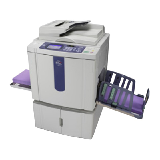
Riso RZ9 Series Manuals
Manuals and User Guides for Riso RZ9 Series. We have
2
Riso RZ9 Series manuals available for free PDF download: Technical Manual, Installation Manual
Riso RZ9 Series Technical Manual (526 pages)
Brand:
Riso
| Category:
Printer
| Size: 77 MB
Table of Contents
Table of Contents
93
Mechanism
94
Main Drive Mechanism
94
Print Drum Angle Detection
95
Main Motor Safety Mechanism
96
Air Dumper Mechanism
97
Disassembly
98
Removing the Pressure Spring
99
Removing the Main Belt
100
Removing the Main Motor Pulley Assembly
102
Removing the Main Shaft Assembly
103
Separation Pump Assembly
105
Separation Pump Solenoid
105
Air Dumper Assembly
106
Piston
109
Removing the Rear Cover Safety SW
110
Adjustment
111
Print-Drum <Position-A> Adjustment
111
Print-Drum <Position-B> Stop Position Adjustment
111
Mechanism
114
Paper Feed Tray Mechanism
114
Paper Feed Tray Elevation Mechanism
115
Upper Limit Position of the Paper Feed Tray
116
Paper Feed Tray Safety Mechanism
117
Paper Volume Detection Mechanism
118
Paper Feed Pressure Adjustment Mechanism
119
Paper Feed Reverse-Rotation Prevention Mechanism
120
First Paper Feed Operation
121
Paper Feed Adjustment (from the Function Tab of the Operation Panel)
122
Paper Stripping Mechanism
123
Disassembly
124
Removing the Paper Feed Tray Unit
124
Removing the Paper Detection Sensor, Paper Size Detection Sensor, and Paper Width
126
Potentiometer
126
Removing the Scraper and Pickup Roller
130
Removing the Paper Feed Roller Assembly
132
Removing the Paper Feed Tray Button and Paper Feed Tray Upper Safety Switch
133
Removing the Elevator Upper-Limit Sensors and Paper Feed Pressure Sensor
135
Removing the Paper Feed Reverse-Rotation Prevention Solenoid
136
Removing the Paper Feed Clutch
137
Removing Paper Volume Sensors a and B
139
Removing the Elevator Motor
140
Removing the Elevator Lower-Limit Sensor and Paper Feed Tray Lower Safety Switch
141
Removing the Stripper Pad Unit
142
Removing the Stripper Pad Assembly
143
Adjustment
144
Elevator Upper-Limit Sensor Position Adjustment
144
Stripper Pad Adjustment
145
Paper Feed Clutch on Angle Adjustment
146
Paper Feed Clutch off Angle Adjustment
146
Paper-Width Potentiometer Adjustment
146
Mechanism
148
Basic Structure
148
Paper Feed Tray No.1
148
Feed Tray Elevating Mechanism
151
Paper Transport Mechanism
152
Vertical Transfer Unit
153
Disassembly
154
Removing the Covers
154
Removing the Paper-Feed Trays
156
Removing the Parts of the Paper-Feed Tray Section
157
Removing the Pickup Roller and Scraper
159
Removing the Parts on the Rear
160
Removing the Transfer Unit
162
Removing the Parts on the Transfer Unit
164
Vertical Transfer Unit
167
Adjustment
170
Upper Limit Sensor Position Adjustment
170
Stripper Adjustment
171
Paper-Width Potentiometer Adjustment
172
Paper Buckle Amount Adjustment
172
Assist Paper Feed Adjustment (for TRAY NO. 1 Only)
173
Lateral Image Position Adjustment
173
Vertical Transfer Unit Nip Pressure Adjustment
174
Mechanism
176
Second Paper Feed Mechanism
176
Vertical Print Position Control
178
Multiple Paper Feed Detection
180
Extended Paper Mode
181
Disassembly
182
Removing the Guide Roller
182
Removing the Paper Sensor
183
Removing the Timing Roller
185
Removing the Vertical Centering Sensor
187
Removing the Print-Positioning Intermediate Gear
188
Removing the Idler Gear
189
Removing the Paper Feed Drive Unit
190
Removing the Print Positioning Pulse Motor
193
Removing the Guide Roller Release Solenoid
194
Adjustment
195
G-Lever Mounting Position Adjustment
195
Paper Feed Skew Adjustment
196
Print Start Position Adjustment
197
Auto-Adjustment of Multiple Paper Feed Detection
198
Mechanism
200
Press Mechanism
200
Pressure Control Mechanism
202
Disassembly
203
Removing the Pressure Roller
203
Removing the Pressure Lever:spring & Pressure Lever;Cam
204
Removing the Pressure Lever Shock Absorber
205
Removing the Pressure HP Sensor
206
Removing the Pressure Control Motor
207
Adjustment
208
Mounting Position of the Pressure Lever
208
Mechanism
212
Paper Ejection Mechanism
212
Paper Separator Mechanism
213
Paper-Ejection-Wing Mechanism
214
Paper Receiving Tray Angle Mechanism
216
Auto-Control Paper Receiving Tray Mechanism
217
Fence Sliding Mechanism
219
Sliding Operations at the Beginning of the Print Operation
221
Disassembly
222
Removing the Paper Receiving Tray
222
Removing the Suction Unit
223
Removing the Paper Ejection Motor and Paper Ejection FG Sensor
225
Removing the Paper Ejection Wing HP Sensor
226
Removing the Paper Ejection Wing Pulse Motor
227
Removing the Paper Ejection Sensor and the Transfer Belts
228
Removing the Separation Fan Unit
230
Removing the Separator
232
Removing the Separation Lever
233
Removing the Auto-Control Paper Receiving Tray
234
Removing the Right/Left Fence Belts from Auto-Control Paper Receiving Tray
235
Removing the Paper Guide Pulse Motor from Auto-Control Paper Receiving Tray
236
Removing the Paper Stopper Fence Belt from Auto-Control Paper Receiving Tray
237
Removing the Paper Stopper Drive Motor
238
Adjustment
239
Separator Mounting Position
239
Adjusting the Paper Ejection Suction Plate
241
Mechanism
244
Master on the Drum Check Mechanism (before Printing)
244
Print Drum Set Mechanism
245
Print Drum Lock Mechanism
246
Print Drum Horizontal Sliding Mechanism
247
Print Drum Rotation Mechanism
248
Inking Mechanism
249
Disassembly
250
Removing the Print Drum Horizontal Sliding Unit
250
Removing the Screen Assembly
251
Removing the Master Clamp Base Assembly
253
Removing the Drum Body
254
Removing the Ink Scraper Plate Assembly F & R
257
Removing the Ink Pump Assembly
258
Removing the Ink Bottle Guide Assembly
259
Removing the Ink Bottle Lock Assembly & Antenna PCB
260
Removing the Ink Sensor PCB
261
Removing the Print Drum PCB
262
Removing the Drum Joint
263
Removing the Flange-R
264
Removing the Flange-F
265
Removing the Squeegee Roller
266
Adjustment
270
Squeegee Gap Adjustment
270
Squeegee Pressure Balance Adjustment
272
Master Skew Adjustment
274
Mechanism
276
Clamp Unit Home Positioning Mechanism
276
Clamp Plate Opening Mechanism
277
Drum Position-A Compensation
278
Clamp Plate Master Clamp Mechanism
279
Disassembly
280
Removing the Clamp Unit
280
Removing the Clamp Motor
281
Removing the Clamp Sensors a & B
282
Mechanism
284
Master Removal Mechanism
284
Master on the Drum Check Mechanism (before Master Removal)
285
Removed Master Vertical Transport Mechanism
286
Disposed Master Compression Mechanism
287
Master Disposal Box Safety SW
288
Protect Function
289
Disassembly
290
Removing the Master Disposal Box
290
Removing the Master Compression FG Sensor
291
Removing the Master Compression Motor
292
Removing the Master Removal Unit
293
Removing the Master Removal Sensor & Master Sensor
294
Removing the Master Removal Motor & Master Removal Motor FG Sensor
295
Removing the Master Compression Plate HP Sensor
296
Removing the Master Disposal Box Safety SW
297
Removing the Master Removal Roller (Bottom)
298
Removing the Master Compression Plate
300
Removing the Pulley Shaft
301
Removing the Master Removal Roller (Upper)
302
Removing the Round Belts
303
Removing the Master Removal Housing Assembly
304
Mechanism
308
Original Scanning Mechanism
308
Flatbed Initialization Movement
310
Stage-Glass Original Detection Mechanism
311
FB Auto-Base-Control
311
FB Scanning Mechanism
312
Original Size-Detection Mechanism
312
Disassembly
313
Removing the Scanner Unit
313
Removing the Stage Glass
314
Removing the FB Original Detection Sensor
315
Removing the Original Size Detection Sensors
316
Removing the Scanner Lamp
317
Removing the CCD Unit
318
Removing the FB/AF HP Sensor
319
Removing the FB Read Pulse Motor
320
Adjustment
321
FB Read Pulse Motor Speed Adjustment (Image Elongation & Shrinkage in Scanning)
321
FB Scan Start Position Adjustment
321
FB Horizontal Scan Position Adjustment
321
Mechanism
324
AF Original Set Mechanism
324
AF Original Size-Detection Mechanism
326
AF Set Detection Mechanism
326
AF Original Scanning Mechanism (with Automatic Base Control)
327
AF Original Scanning Mechanism
328
Removing the Original Pickup Asembly
330
Removing the Original Pickup Roller
332
Removing the Original Stripper Roller
333
Removing the Original Stripper Pad Assembly
334
Removing the AF Original in Sensorr
335
Removing the AF Read Pulse Motor
336
Removing Other Rollers
337
Removing the Registration Roller
340
Removing the Read Roller No. 1
341
Removing the Read Roller No. 2
342
Removing the Original Ejection Roller
343
Adjustment
345
AF Scan Start-Position Adjustment
345
AF Horizontal-Scan Position Adjustment
345
AF Read Pulse-Motor Speed Adjustment (Elongation & Shrinkage)
345
AF Original Guide Fence Potentiometer Adjustment
346
AF Original in Sensor Sensitivity Adjustment
346
Mechanism
348
Basic Mechanism
348
Original Size Detection Mechanism
349
Electrical Component Description
350
Original Feeding and Transporting Mechanism
352
Disassembly
354
Removing the Pick-Up Roller , Feed Belt and the Separation Roller
354
Removing the Original Set Sensor and the Original Reverse Sensor
355
Removing the Original Width Sensor Board , the Original Length Sensor , and Trailing Edge Sensor
356
Removing the Covers
357
Removing the Left Cover
358
Removing the Registration Sensor
358
Removing the Original Exit Sensor
359
Mechanism
362
Master Making Unit Components
362
Set Detection Mechanism
363
Master Cutting Mechanism
364
TPH (Thermal Print Head) Elevation Mechanism
365
Master Set Mechanism
366
Master Making Movement
367
Disassembly
368
Removing the Master Making U Lock Sensor
368
Removing the Print Drum, Master Making U Release Button, Lock Solenoid, and Safety Switch
369
Removing the Print Thermal Head Assembly
371
Removing the Thermal Pressure Motor Assembly and the Capacitor PCB
373
Removing the Master End Sensor (Receive) Assembly
375
Removing the Master Detection Sensor and Master End Sensor (Send) Assembly
376
Removing the Antenna PCB
379
Removing the Write Pulse Motor Assembly
380
Removing the Write Roller
381
Removing the Load Pulse Motor Assembly
382
Removing the Cutter Cover Assembly
383
Removing the Clamping Guide Roller
384
Removing the Cutter Guide Assembly
385
Removing the Cutter Unit
386
Removing the Load Roller (Bottom)
387
Removing the Master Making Unit
388
Removing the Master Stocker Roller (Bottom)
391
Adjustment
393
Thermal Power of Thermal Print Head
393
Master Clamp Range Adjustment
393
Write Start Position Adjustment
393
Horizontal Write Position Adjustment
394
Master Cut Length Adjustment
394
Master Making Image Elongation and Shrinkage Adjustment
394
Master Making Length Adjustment
394
Master Positioning Sensor Sensitivity Adjustment
395
Explanation of Panel Messages
398
Error-Code Displays
398
List of Error Types
399
Detailed List of Panel Messages
403
B09 , B11
440
Errors Requiring Special Attention
441
Test Mode Procedures
444
Individual Test Procedures
445
System & Control Panel Test Mode
446
Image Processing / Scanning Test Mode
452
Master-Making / Master-Disposal Test Mode
454
Paper-Feeding / Paper-Ejection Test Mode
457
Print-Drum / Printing Test Mode
463
Protected Area Test Mode
468
Options (AF) Test Mode
471
Options (Job-Separator) Test Mode
473
Options (Memory) Test Mode
473
Options (Linked-Printer) Test Mode
474
Options (Auto-Stacker) Test Mode
475
Options (Vendor) Test Mode
475
Multi-Tray Paper Feeder Test Mode
476
Machine Setup During the Installation
480
Sales Test Mode
481
Power-Saving (Low-Power) Mode
482
Main Motor Free-Rotation Button (Print Drum Free-Rotation Button)
482
Firmware Downloading Procedure
483
DSP Software (Multi-Tray Paper Feed Unit) Downloading Procedure
483
Replacement of the Mechanical Control PCB
484
Replacement of the MTPF PCB
485
Replacement of the SH4F PCB
485
Battery Replacement
485
Replacement of the Print Drum PCB
486
Print Position Adjustment Procedures
486
Motors
506
Fans, Solenoids, Solenoid Clutches
508
Photoelectric Sensors
510
Other Sensor, Switches, Volume Dial
512
AF (Auto-Document Feeder) - Option
514
Electric Parts Particular to RZ 9 (1) - Duplex AF
515
Electric Parts Particular to RZ 9 (2) - Auto-Stacking Tray
516
Electric Parts Particular to RZ 9 (3) - Multi-Tray Paper Feed-1
518
Electric Parts Particular to RZ 9 (4) - Multi-Tray Paper Feed-2
520
Electric Parts Particular to RZ 9 (5) - Others
522
Advertisement
Riso RZ9 Series Installation Manual (60 pages)
Printer Driver
Brand:
Riso
| Category:
Printer Accessories
| Size: 1 MB
Table of Contents
Introduction
3
Procedure before Printing
4
Connection Methods
6
Table of Contents
7
Installing the Printer Driver
9
I Connection Via USB Cable
10
Installing the Printer Driver
10
Creating a USB Port
24
USB Device Association
25
I Connection Via Other Cables
26
Connecting with PC
26
Installing the Printer Driver
27
Uninstalling the Printer Driver
39
I Uninstall the Printer Driver
40
Manually Installing / Uninstalling the Printer Driver
43
For Windows 2000 / Windows XPI Manual Installation
44
Connection Via USB Cable
44
Connection Via Other Cables
45
I Manual Uninstallation
46
For Windows Vista I Manual Installation
47
Connection Via USB Cable
47
Connection Via Other Cables
49
I Manual Uninstallation
50
For Windows 7 I Manual Installation
51
Connection Via USB Cable
51
Connection Via Other Cables
53
I Manual Uninstallation
54
For Windows 8 / Windows 8.1
55
I Manual Installation
55
Connection Via USB Cable
55
Connection Via Other Cables
57
I Manual Uninstallation
58
Advertisement
Related Products
Riso RZ5 Series
Riso RZ 970 Series
Riso RZ977 Series
Riso RZ1070
Riso RZ1090
Riso RZ370
Riso RZ230
Riso RZ200
Riso RZ2xx Series
Riso RZ3xx Series
Riso Categories
Printer
All in One Printer
Disc Duplicator
Printer Accessories
Copier
More Riso Manuals
Login
Sign In
OR
Sign in with Facebook
Sign in with Google
Upload manual
Upload from disk
Upload from URL