Sign In
Upload
Manuals
Brands
OKIDATA Manuals
Printer
Pacemark 3410
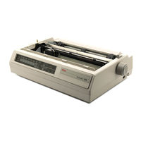
OKIDATA Pacemark 3410 Manuals
Manuals and User Guides for OKIDATA Pacemark 3410. We have
5
OKIDATA Pacemark 3410 manuals available for free PDF download: Service Handbook, User Manual, Service Manual, Instruction Manual
OKIDATA Pacemark 3410 Service Handbook (308 pages)
Brand:
OKIDATA
| Category:
Printer
| Size: 2 MB
Table of Contents
Table of Contents
5
Course Administration
15
Overview
17
Recommendations
18
Information Updates
19
Notices
19
Where to Send Testing Materials
20
Missing Items
21
Course Path
22
Service Training
23
On-Site Service Support Agreement
27
General Information
27
Where to Send the Agreement
27
Service Authorization
28
General Information
28
Where to Send Your Test Materials
28
On-Site Service Support Agreement: Pacemark 3410
30
Answer Sheet: Pacemark 3410
31
Certification Test: Pacemark 3410
32
Course Critique: Pacemark 3410
43
Section One: Specifications
45
Overview
47
General Information
47
Physical Specifications
48
Printer Dimensions
48
Printer Weight
48
Power Requirements
48
Input Power
48
Power Consumption
48
Environmental Conditions
49
Acoustic Rating
49
Altitude
49
Ambient Temperature and Relative Humidity
49
Agency Approvals
49
Listings
49
Operational Specifications
50
Character Matrix Sizes
50
Characters Per Line
50
Character Pitches
50
Character Sets
50
Emulations
51
Fonts
51
Standard
51
Front Panel Switches
52
Graphics Resolution
52
Interface Methods
52
Optional
52
Standard
52
Line Feed Increments
52
Line Feed Time
52
Menu Mode
53
Paper Feed Methods
53
Paper Feed Paths
53
Paper Loading
53
Paper out Detection
53
Paper Tear Capabilities
54
Print Method
54
General Information
54
Overheat Protection
54
Printhead Type
54
Print Modes
54
Print Speeds
54
Paper Specifications
55
Types
55
Card Stock
55
Continuous Form
55
Cut Sheet
56
Envelopes
56
Labels
57
Transparency
57
Length
57
Number of Copies
59
Thickness
59
Weight
59
Width
59
Memory Specifications
60
Eeprom
60
Ram
60
Rom
60
Consumables
60
Ribbon
60
Options
61
Cut Sheet Feeders
61
Pull Tractor with Acoustic Cover
61
Microline/Pacemark Emulation Chip Set
61
Printer Stands
61
Twin-Ax / Co-Ax
61
Reliability
62
Mean Time before Failure (MTBF)
62
Mean Time to Repair (MTTR)
62
Printer Life
62
Printhead Life
62
Ribbon Life
62
Warranty (Limited)
62
Service
62
Section Two: Principles of Operation
63
Electrical Operation
65
General Information
65
Microprocessor (MPU) and Peripheral Circuits
66
Dram
66
Eeprom
66
Microprocessor
66
Program ROM for the MPU
66
Bail Motor Phasing Control
67
Dot on Timing Signal Generation
67
Interface/Motor Control LSI
67
Line Feed Motor Phasing Control
67
Printhead / Bottom Tractor Feed Control LSI
67
Printhead Drive Control
67
Space Motor Enable / Speed Control
67
Initialization
68
Block Diagram
69
Interface Control
70
Parallel Interface
70
RS232-C Serial Interface
71
Printhead Drive Circuit
72
Spacing Drive Circuit
72
Line Feed Circuit
73
Alarm Circuits
74
Cover Open Alarm Circuit
74
Fault Alarm Circuit (in Power Supply Unit)
74
Printhead Overheat Alarm Circuit
74
Paper End Detection Circuit
74
Power Supply
75
Voltage / Signal Table
75
Mechanical Operation
76
Printhead Mechanism
76
Head Gap Adjusting
76
Spacing Mechanism
78
Spacing Operation
78
Ribbon Drive Mechanism
79
Ribbon Cartridge
79
Ribbon Feed Operation
79
Paper Feed Mechanism
80
Friction (Sheet) Feed
80
Tractor (Continuous) Feed
80
Paper-End Detection Mechanism
81
Continuous (Bottom) Feed Paper-End
81
Continuous (Rear) Feed Paper-End
81
Friction Feed (Cut-Sheet) Paper-End
81
Automatic Paper Loading
82
Continuous Sheet (Rear Feed) SASF
82
Cut-Sheet Paper
82
Paper Park Feature
83
Section Three: Maintenance
85
Overview
87
General Information
87
Maintenance Items
88
Maintenance Precautions
89
Disassembly/Assembly Procedures
91
General Information
91
Printhead (with Preliminary Items)
92
Ribbon Protector Assembly
94
Upper Cover Assembly
96
Operator Panel
98
Interface Connector Board
100
Main Logic (CBNP) Board
102
Printer Mechanism
104
Power Supply Unit
106
Printer Unit
108
Btfd Pcb
110
Tension Spring
112
Bottom Push Mechanism and Front Door Assembly
114
Drive Pulley and Belt
116
Tractor Assembly (BTF)
118
Line Feed Motor (BTF)
120
Platen Assembly
122
Paper Pressure Guide
124
Line Feed Motor Assembly
126
Ribbon Cartridge Bracket
128
Fan Assembly
130
Head Cable Assembly
132
Carriage and Carriage Shaft
134
Ribbon Feed Assembly
136
Space Motor Assembly
138
Space Belt
140
Sensor Board (LPRW)
142
Bail Motor/Gear Assembly
144
Paper Bail Assembly
146
Rear Feed Tractor Assembly
148
Printhead Gap/Release Lever Microswitches
150
Release Lever / Gear Assemblies
152
Printer Adjustments
155
General Information
155
Printhead Gap
156
General Information
156
Check Phase (Steps 13 - 16)
157
Parallel Adjustment Phase (Steps 10 - 12)
157
Printhead Gap Modification Phase (Steps 7 - 9)
157
Setup Phase (Steps 1 - 6)
157
Diagram
159
General Information
160
Microswitch 2 Modification
160
Procedure
160
Verification
161
Read Me First
162
90 Day On-Site Warranty Extension
163
Line Feed Belt Tension
164
Key Combinations
167
Table
167
Menu Operation
168
General Description
168
Menu Mode
168
Printing the Menu
169
Reset Menu and Top of Form to Factory Defaults
170
Reset Menu to Factory Defaults
170
Limited Operation
171
Menu Settings
172
Top of Form
179
General Information
179
Reset Top of Form and Menu to Factory Defaults
179
Setting Top of Form
179
Paper Park
181
General Information
181
Procedure: Continuous Feed to Single Sheet
181
Procedure: Single Sheet to Continuous Feed
181
Forms Tear off
182
General Information
182
Checking Top of Form with Form Tear off Activated
183
Setting
183
Using
183
Resets
185
Reset Menu and Top of Form to Factory Defaults
185
Reset Menu to Factory Defaults
185
Cleaning
186
General Information
186
Diagram of Cleaning Locations
187
Table of Cleaning Locations
187
Lubrication
189
General Information
189
Areas Not Lubricated
190
Lubrication Diagrams
191
Right and Left Sides of Printer
191
Carriage Shaft
192
Ribbon Feed Assembly
192
Space Motor Assembly
193
Tractor Feed Assembly
193
Shipping Instructions
194
Return for Service
194
All Other Returns
195
Section Four: Failure Analysis
197
Overview
199
Introduction
199
Printer Serial Number Identification
201
Reporting Problems
202
General Information
202
Problem Lists
202
Reporting Methods
203
Course Critique
203
Fax Number
203
Information Provided
203
Mailing Address
203
Okilink II
203
Troubleshooting Updates
204
General Information
204
Okilink II
204
Faxable Facts
204
Technical Service Bulletins
204
Troubleshooting Tips
205
Preliminary Checks
205
Problem Categories
206
ALARM Lamp Blinks (Fatal Errors)
206
ALARM Lamp Lights (Paper End/Jam Conditions)
206
Operational Errors
206
START here Flowchart
207
Tips for Preventing Image Problems
208
Common Problems
209
Abnormal Output
212
Output Samples
212
Drifting Margin
212
Inconsistent Line Feed
212
Light Print on the Entire Page
212
Smeared Print
212
Uneven Print Density
212
Fault Alarms
215
Error Indications
215
REPAIR ANALYSIS PROCEDURES (Raps)
216
Using the Raps
216
RAP Index
217
RAP 01: Power Lamp Does Not Light
218
RAP 02: Spacing Error
220
RAP 03: Head Homing Error
222
RAP 04: Bail Homing Error
224
RAP 05: Ribbon Feed Problem
225
RAP 06: Wrong Character, Character Omission or Dot Omission
226
RAP 07: Line Feed Problem
228
RAP 08: Malfunction of Operator Panel Switch
229
Parallel
230
RAP 09: Data Receiving Failure
230
Serial
231
RAP 10: ALARM Lamp on
233
RAP 11: Bottom Tractor Feed Unit (BTFU) Problem
234
Printer Tests
237
Rolling ASCII Test
237
General Information
237
Procedure
238
Sample
239
Font Sample Test
240
General Information
240
Procedure
240
Sample
241
Serial Interface Diagnostic
242
General Information
242
Procedure
242
Serial Cable Information
243
Serial Interface Signal Requirements
243
Hexadecimal Dump
244
Example
244
General Information
244
Procedure
244
Resistance Checks
245
General Description
245
Layout Diagram
246
Printhead
247
Line Feed Motor
247
Space Motor
248
Bail Motor
248
Appendix Aboard Diagrams
249
Overview
251
General Information
251
A.1 Overview
251
Index to Charts
252
A.2 Index to Charts
252
Main Logic Board (CBNP
254
Power Supply Board
256
Interface Board (HKTY
258
Sensor Board (LPRW
260
Operator Panel Board (OPML
262
Bottom Tractor Feed Unit Board (BTFD
264
Appendix B: Illustrated Parts Listing
267
Overview
269
General Information
269
B.1 Overview
269
Format
270
Current Part Numbers
271
Definition of Terms
272
Assemblies
272
B.1.02 Definition of Terms
272
Blank
272
Consumable
272
Document
272
Drivers
272
Firmware
272
Option RSPL
272
Rspl
272
Technical Service Bulletins
273
Parts Ordering Information
274
Service Center Reference Guide
274
Placing a Parts Order
275
Charts
276
B.2 Charts
276
B.2.01 Printer
278
Printer
278
Upper Cover Assembly
280
B.2.03 Printer Unit
282
Printer Unit
282
Operator Panel Assembly
284
B.2.05 Carriage Assembly
286
Carriage Assembly
286
B.2.06 Printer Mechanism (1 of 2)
288
Printer Mechanism (1
288
Printer Mechanism (1 of 2)
288
B.2.07 Printer Mechanism (2 of 2)
290
Printer Mechanism (2 of 2)
290
Bottom Tractor Feed Unit
292
B.2.09 Options
294
Options
294
Pull Tractor Unit
296
Pull Tractor Unit (Option
296
B.2.11 Packing Materials
298
Packing Materials
298
B.2.12 Consumables
300
Consumables
300
B.2.13 Documentation
302
Documentation
302
Advertisement
Okidata Pacemark 3410 Service Manual (249 pages)
Brand:
Okidata
| Category:
Printer
| Size: 1 MB
Table of Contents
Table of Contents
2
About this Manual
6
1 Product Specifications
7
Overview
7
Physical Specifications
8
Power Requirements
9
Environmental Conditions
10
Agency Approvals
11
Operational Specifications
12
Paper Specifications
18
Memory Specifications
21
Consumables
22
Options
23
Reliability
24
2 Principles of Operation
25
Electrical Operation - General Information
25
Microprocessor (MPU) and Peripheral Circuits
26
Initialization
28
Interface Control
30
Printhead Drive Circuit
32
Spacing Drive Circuit
33
Line Feed Circuit
34
Alarm Circuits
35
Paper End Detection Circuit
36
Power Supply
37
Mechanical Operation - Printhead Mechanism
39
Spacing Mechanism
41
Ribbon Drive Mechanism
42
Paper Feed Mechanism
44
Paper-End Detection Mechanism
46
Automatic Paper Loading
48
Paper Park Feature
49
3 Maintenance & Disassembly
50
Overview
50
Maintenance Items
51
Maintenance Precautions
52
Disassembly/Assembly Procedures
53
Printhead (with Preliminary Items)
54
Ribbon Protector Assembly
56
Upper Cover Assembly
58
Operator Panel
60
Interface Connector Board
62
Main Logic (CBNP) Board
64
Printer Mechanism
66
Power Supply Unit
68
Printer Unit
70
Btfd Pcb
71
Tension Spring
73
Bottom Push Mechanism and Front Door Assembly
74
Drive Pulley and Belt
76
Tractor Assembly (BTF)
78
Line Feed Motor (BTF)
80
Platen Assembly
81
Paper Pressure Guide
83
Line Feed Motor Assembly
85
Ribbon Cartridge Bracket
86
Fan Assembly
88
Head Cable Assembly
89
Carriage and Carriage Shaft
91
Ribbon Feed Assembly
93
Space Motor Assembly
95
Space Belt
97
Sensor Board (LPRW)
99
Bail Motor/Gear Assembly
100
Paper Bail Assembly
101
Rear Feed Tractor Assembly
103
Printhead Gap/Release Lever Microswitches
105
Release Lever / Gear Assemblies
106
Printer Adjustments
107
Printhead Gap
108
Line Feed Belt Tension
113
Key Combinations
114
Menu Operation
115
Menu Settings
116
Top of Form
118
Paper Park
125
Forms Tear off
126
Resets
128
Cleaning
129
Lubrication
131
Areas Not Lubricated
132
Lubrication Diagrams
133
Right and Left Sides of Printer
134
Carriage Shaft
135
Ribbon Feed Assembly
136
Space Motor Assembly
137
Tractor Feed Assembly
138
Shipping Instructions
139
All Other Returns
140
4 Failure & Repair Analysis
142
Printer Serial Number Identification
142
Reporting Problems
143
Problem Lists
144
Reporting Methods
145
Troubleshooting Updates
146
Troubleshooting Tips
147
Problem Categories
148
START here Flowchart
149
Tips for Preventing Image Problems
150
Common Problems
151
Abnormal Output
154
Fault Alarms
156
Error Indications
156
Repair Analysis Procedures (RAPS)
158
RAP Index
159
RAP 01: Power Lamp Does Not Light
160
RAP 02: Spacing Error
162
RAP 03: Head Homing Error
164
RAP 04: Bail Homing Error
166
RAP 05: Ribbon Feed Problem
167
RAP 06: Wrong Character, Character Omission or Dot
168
RAP 08: Malfunction of Operator Panel Switch
171
RAP 09: Data Receiving Failure
172
RAP 10: ALARM Lamp on
174
RAP 11: Bottom Tractor Feed Unit (BTFU) Problem
175
Font Sample Test
180
Sample - Part 1
183
Serial Interface Diagnostic
184
Hexadecimal Dump
187
Resistance Checks
188
Printhead
189
Line Feed Motor
190
Space Motor
191
Bail Motor
192
A.1 Overview
193
A.2 Index to Charts
194
A.2.01 Main Logic Board (CBNP)
196
A.2.02 Power Supply Board
199
A.2.03 Interface Board (HKTY)
202
A.2.04 Sensor Board (LPRW)
204
A.2.05 Operator Panel Board (OPML)
206
A.2.06 Bottom Tractor Feed Unit Board (BTFD)
208
B.1.02 Definition of Terms
211
B.1.03 Parts Ordering Information
213
B.2 Charts
214
B.2.01 Printer
217
B.2.02 Upper Cover Assembly
218
B.2.03 Printer Unit
221
B.2.04 Operator Panel Assembly
225
B.2.05 Carriage Assembly
227
B.2.08 Bottom Tractor Feed Unit
235
B.2.09 Options
237
B.2.10 Pull Tractor Unit (Option)
240
B.2.11 Packing Materials
242
B.2.12 Consumables
245
B.2.13 Documentation
246
OKIDATA Pacemark 3410 User Manual (273 pages)
Brand:
OKIDATA
| Category:
Printer
| Size: 14 MB
Advertisement
OKIDATA Pacemark 3410 User Manual (273 pages)
Users' Guide for the PM3410
Brand:
OKIDATA
| Category:
Printer
| Size: 12 MB
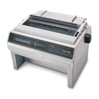
OKIDATA Pacemark 3410 Instruction Manual (9 pages)
Printing Forms with the Pacemark Printer
Brand:
OKIDATA
| Category:
Printer
| Size: 0 MB
Table of Contents
Printing Forms
4
Using Printer Menus
5
Printer Button
5
Changing Printer Settings
6
Advertisement
Related Products
Okidata MICROLINE 321
Okidata MICROLINE 320
OKIDATA Microline 393C
OKIDATA Microline 393
OKIDATA Microline 395
OKIDATA Microline 395C
OKIDATA Pacemark 4410
OKIDATA 120
OKIDATA 610e
OKIDATA 610e-PS
OKIDATA Categories
Printer
Printer Accessories
Fax Machine
Computer Hardware
All in One Printer
More OKIDATA Manuals
Login
Sign In
OR
Sign in with Facebook
Sign in with Google
Upload manual
Upload from disk
Upload from URL