Sign In
Upload
Manuals
Brands
Basler Manuals
IP Camera
A500k
Basler A500k Manuals
Manuals and User Guides for Basler A500k. We have
3
Basler A500k manuals available for free PDF download: Wood Burning Fireplace, User Manual
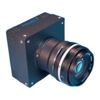
Basler A500k User Manual (150 pages)
area scan cameras
Brand:
Basler
| Category:
Color Camera
| Size: 2.38 MB
Table of Contents
Table of Contents
5
1 Introduction
9
Camera Versions
9
Performance Specifications
10
Digital Responsivity
12
Environmental Requirements
13
Precautions
14
2 Camera Interface
15
Connections
15
General Description
15
Pin Assignment for the MDR 26 Camera Link Connector(S)
17
Pin Assignment for the Power Connector
19
Pin Assignment for the Flash Trigger Receptacle
19
Pin Assignment for the VGA Monitor Output
21
(A504K Only)
21
Cable Information
21
Camera Link Cable
21
Power Cable
22
Camera Link Implementation in the A500K
23
Input Signals
27
Exsync: Controls Frame Readout and Exposure Time
27
Exflash from the Frame Grabber
27
Output Signals
28
Pixel Clock
28
Line Valid Bit
28
Frame Valid Bit
28
Video Data
28
Video Data Output for the A504K
35
Video Data Output for the A503K
39
Video Data Output for the A501K
43
Flash Trigger Signal
45
VGA Monitor Output (A504K Only)
46
Serial Communication
47
Making the Serial Connection
47
Converting Camera Link Output to RS-644 with a K-BIC (A501K Only)
47
RS-644 Serial Communication
47
DC Power
48
Power Control: Full Function and Standby
48
Status LED
49
3 Basic Operation and Features
51
Functional Description
51
Exposure Time Control Modes
54
Exsync Controlled Operation
54
Free Run
56
Exposure Time Control Modes in Detail
58
Exsync, Edge-Controlled Mode
60
Exsync, Edge-Controlled Mode with Asynchronous Timing
61
Exsync, Edge-Controlled Mode with Synchronous Timing 1
62
Exsync, Edge-Controlled Mode with Synchronous Timing 2
63
Exsync, Level-Controlled Mode
64
Exsync, Level-Controlled Mode with Asynchronous Timing
65
Exsync, Level-Controlled Mode with Synchronous/Asynchronous
66
Timing
66
Exsync, Level-Controlled Mode with Synchronous Timing 1
67
Exsync, Level-Controlled Mode with Synchronous Timing 2
68
Exsync, Programmable Mode
69
Exsync, Programmable Mode with Asynchronous Timing
70
Exsync, Programmable Mode with Synchronous/Asynchronous
71
Timing
71
Exsync, Programmable Mode with Synchronous Timing 1
72
Exsync, Programmable Mode with Synchronous Timing 2
73
Free-Run Mode
74
Free-Run Mode with Asynchronous Timing
75
Free-Run Mode with Synchronous/Asynchronous Timing
76
Free-Run Mode with Synchronous Timing 1
77
Free-Run Mode with Synchronous Timing 2
78
Free-Run VGA Mode (A504K Only)
79
Long Exposure Compensation (A504K, A503K Only)
80
Max Exposure Time at Max Speed (A504K Only)
81
Gain and Offset
82
Gain Settings in more Detail
83
Offset Settings in more Detail
83
DSNU Constancy (A503K Only)
84
Shutterline Correction (A503K Only)
84
Digital Shift
85
How Digital Shift Works
85
Precautions When Using Digital Shift
87
Area of Interest (AOI)
88
Changes to the Maximum Frame Rate with Area of Interest
90
Dynamic Area of Interest (A504K, A503K Only)
91
Area of Interest Stamp (A504K, A503K Only)
91
Area of Interest with the VGA Monitor Output (A504K Only)
92
Test Images
93
Gray Scale Test Image
94
Running Line Test Image
94
White Screen Test Image
94
Configuration Sets
95
Camera Status
96
4 Configuring the Camera
97
Configuring the Camera with the Camera Configuration Tool Plus (CCT+)
98
Opening the Configuration Tool
98
Closing the Configuration Tool
98
Configuration Tool Basics
99
Configuration Tool Help
100
Configuring the Camera with Binary Programming Commands
101
Command Frame and Response Format
102
Error Checking
103
Ack/Nak
103
Read Command
103
Time-Outs
103
Write Command
104
Example Commands
105
Read Command
105
Write Command
105
Calculating the Block Check Character
106
Commands for Setting Camera Parameters
107
Exposure Time Control Mode
107
Timer 1
108
Timer 2
108
Long Exposure Compensation (A504K, A503K Only)
109
Gain
110
Negative Offset
110
Positive Offset
111
DSNU Constancy and Shutterline Correction Enable
112
Shutterline Correction (A503K Only)
113
Digital Shift
114
Area of Interest Starting Column
115
Area of Interest Width in Columns
115
Area of Interest Height in Lines
116
Area of Interest Starting Line
116
A503K Only)
117
Area of Interest Stamp and Dynamic Area of Interest
117
Flashctrl: Flash Trigger Modes
118
Test Image Command
119
Query Commands
120
Read Model Information
120
Read Product ID
120
Read Vendor Information
120
Read Camera Version
121
Read EEPROM Firmware Version
121
Read Serial Number
121
Read FPGA Firmware Version
122
Read Microcontroller Firmware Version
122
Read Temperature
122
Commands for Manipulating Configuration Sets
123
Copy the Factory Set or the User Set into the Work Set (Profile Load)
123
Copy the Work Set into a User Set (Profile Save)
124
Select the Startup Pointer (Profile Startup)
125
Camera Status Command
126
Bitrate Command
127
Camera Reset Command
128
Power Control Command
128
5 Mechanical Considerations
129
Camera Dimensions and Mounting Facilities
129
F-Mount Adapter Dimensions
131
Positioning Accuracy of the Sensor Chip
132
Mechanical Stress Test Results
133
6 Troubleshooting and Support
135
Troubleshooting
135
Fault Finding Using the Camera's LED
135
Troubleshooting Charts
136
No Image
136
Poor Quality Image
138
Interfacing
139
Serial Communication
140
Technical Support
141
Technical Support Resources
141
Obtaining an RMA Number
141
Before Contacting Basler Technical Support
141
Revision History
145
Index
147
Advertisement
Basler A500k Wood Burning Fireplace (150 pages)
Brand:
Basler
| Category:
Digital Camera
| Size: 2.51 MB
Table of Contents
Table of Contents
5
1 Introduction
9
Camera Versions
9
Performance Specifications
10
Digital Responsivity
12
Environmental Requirements
14
Precautions
15
2 Camera Interface
17
Connections
17
General Description
17
Pin Assignment for the MDR 26 Camera Link Connector(S)
19
Pin Assignment for the Power Connector
21
Pin Assignment for the Flash Trigger Receptacle
21
Pin Assignment for the VGA Monitor Output (A504K/Kc Only)
23
Cable Information
23
Camera Link Cable
23
Power Cable
24
Camera Link Implementation in the A500K
25
Input Signals
29
Exsync: Controls Frame Readout and Exposure Time
29
Exflash from the Frame Grabber
29
Output Signals
30
Pixel Clock
30
Line Valid Bit
30
Frame Valid Bit
30
Video Data
30
Video Data Output for the A504K/Kc
37
Video Data Output for the A503K
41
Video Data Output for the A501K/Kc
45
Flash Trigger Signal
47
VGA Monitor Output (A504K/Kc Only)
48
Serial Communication
49
Making the Serial Connection
49
Converting Camera Link Output to RS-644 with a K-BIC (A501K/Kc Only)
49
DC Power
50
Power Control: Full Function and Standby
50
Status LED
50
3 Basic Operation and Features
51
Functional Description
51
Block Diagram
53
Exposure Time Control Modes
54
Exsync Controlled Operation
54
Free Run
56
Exposure Time Control Modes in Detail
58
Exsync, Edge-Controlled Mode
60
Exsync, Edge-Controlled Mode with Asynchronous Timing
61
Exsync, Edge-Controlled Mode with Synchronous Timing 1
62
Exsync, Edge-Controlled Mode with Synchronous Timing 2
63
Exsync, Level-Controlled Mode
64
Exsync, Level-Controlled Mode with Asynchronous Timing
65
Exsync, Level-Controlled Mode with Synchronous/Asynchronous
66
Timing
66
Exsync, Level-Controlled Mode with Synchronous Timing 1
67
Exsync, Level-Controlled Mode with Synchronous Timing 2
68
Exsync, Programmable Mode
69
Exsync, Programmable Mode with Asynchronous Timing
70
Exsync, Programmable Mode with Synchronous/Asynchronous
71
Timing
71
Exsync, Programmable Mode with Synchronous Timing 1
72
Exsync, Programmable Mode with Synchronous Timing 2
73
Free-Run Mode
74
Free-Run Mode with Asynchronous Timing
75
Free-Run Mode with Synchronous/Asynchronous Timing
76
Free-Run Mode with Synchronous Timing 1
77
Free-Run Mode with Synchronous Timing 2
78
Free-Run VGA Mode (A504K/Kc Only)
79
Long Exposure Compensation (A504K/Kc, A503K Only)
80
Max Exposure Time at Max Speed (A504K/Kc Only)
81
Gain and Offset
83
Gain Settings in more Detail
84
Offset Settings in more Detail
84
DSNU Constancy (A503K Only)
85
Shutterline Correction (A503K Only)
85
Digital Shift
86
How Digital Shift Works
86
Precautions When Using Digital Shift
88
Area of Interest (AOI)
89
Changes to the Maximum Frame Rate with Area of Interest
91
Dynamic Area of Interest (A504K/Kc, A503K Only)
92
Area of Interest Stamp (A504K/Kc, A503K Only)
92
Area of Interest with the VGA Monitor Output (A504K/Kc Only)
93
Test Images
94
Gray Scale Test Image
95
Color Test Image (A504Kc and A501Kc Only)
95
Running Line Test Image
96
White Screen Test Image
96
Configuration Sets
97
Camera Status
98
4 Configuring the Camera
99
Configuring the Camera with the Camera Configuration Tool Plus (CCT+)
100
Opening the Configuration Tool
100
Closing the Configuration Tool
100
Configuration Tool Basics
101
Configuration Tool Help
102
Configuring the Camera with Binary Programming Commands
103
Command Frame and Response Format
104
Error Checking
105
Ack/Nak
105
Read Command
105
Time-Outs
105
Write Command
106
Example Commands
107
Read Command
107
Write Command
107
Calculating the Block Check Character
108
Commands for Setting Camera Parameters
109
Exposure Time Control Mode
109
Timer 1
110
Timer 2
110
Long Exposure Compensation (A504K/Kc, A503K Only)
111
Gain
112
Negative Offset
112
Positive Offset
113
DSNU Constancy and Shutterline Correction Enable (A503K Only)4-16
114
Shutterline Correction (A503K Only)
115
Digital Shift
116
Area of Interest Starting Column
117
Area of Interest Width in Columns
117
Area of Interest Height in Lines
118
Area of Interest Starting Line
118
Area of Interest Stamp and Dynamic Area of Interest
119
Flashctrl: Flash Trigger Modes
120
Test Image Command
121
Query Commands
122
Read Model Information
122
Read Product ID
122
Read Vendor Information
122
Read Camera Version
123
Read EEPROM Firmware Version
123
Read Serial Number
123
Read FPGA Firmware Version
124
Read Microcontroller Firmware Version
124
Read Temperature
124
Commands for Manipulating Configuration Sets
125
Copy the Factory Set or the User Set into the Work Set (Profile Load)
125
Copy the Work Set into a User Set (Profile Save)
126
Select the Startup Pointer (Profile Startup)
127
Camera Status Command
128
Bitrate Command
129
Camera Reset Command
130
Power Control Command
130
5 Mechanical Considerations
131
Camera Dimensions and Mounting Facilities
131
F-Mount Adapter Dimensions
133
Positioning Accuracy of the Sensor Chip
134
6 Troubleshooting
135
Led
135
Troubleshooting Charts
136
No Image
136
Poor Quality Image
138
Interfacing
139
Serial Communication
140
Before Calling Basler Technical Support
141
Revision History
143
Feedback
145
Index
147
Basler A500k User Manual (131 pages)
Brand:
Basler
| Category:
IP Camera
| Size: 3.17 MB
Table of Contents
Table of Contents
5
1 Introduction
9
Camera Versions
9
Performance Specifications
10
Digital Responsivity
12
Environmental Requirements
14
Precautions
15
2 Camera Interface
17
Connections
17
General Description
17
Pin Assignment for the MDR 26 Camera Link Connector(S)
19
Pin Assignment for the Power Connector
22
Pin Assignment for the Flash Trigger Receptacle
22
Pin Assignment for the VGA Monitor Output (A504K/Kc Only)
24
Cable Information
24
Camera Link Cable
24
Power Cable
24
Camera Link Implementation in the A500K
25
Input Signals
28
Exsync: Controls Frame Readout and Exposure Time
28
Exflash from the Frame Grabber
28
Output Signals
29
Pixel Clock
29
Line Valid Bit
29
Frame Valid Bit
29
Video Data
29
Video Data Output for the A504K/Kc
32
Video Data Output for the A501K/Kc
35
Flash Trigger Signal
38
VGA Monitor Output (A504K/Kc)
39
Serial Communication
40
Making the Serial Connection
40
Converting Camera Link Output to RS-644 with a K-BIC (A501K/Kc Only)
40
DC Power
41
Power Control: Full Function and Standby
41
Status LED
41
3 Basic Operation and Features
43
Functional Description
43
Exposure Time Control Modes
46
Exsync Controlled Operation
46
Free Run
47
Exposure Time Control Modes in Detail
49
Exsync, Edge-Controlled Mode
51
Exsync, Edge-Controlled Mode with Asynchronous Timing
51
Exsync, Edge-Controlled Mode with Synchronous Timing 1
52
Exsync, Edge-Controlled Mode with Synchronous Timing 2
53
Exsync, Level-Controlled Mode
54
Exsync, Level-Controlled Mode with Asynchronous Timing
54
Exsync, Level-Controlled Mode with Synchronous/Asynchronous Timing
55
Exsync, Level-Controlled Mode with Synchronous Timing 1
56
Exsync, Level-Controlled Mode with Synchronous Timing 2
57
Exsync, Programmable Mode
58
Exsync, Programmable Mode with Asynchronous Timing
59
Exsync, Programmable Mode with Synchronous/Asynchronous Timing
60
Exsync, Programmable Mode with Synchronous Timing 1
61
Exsync, Programmable Mode with Synchronous Timing 2
62
Free-Run Mode
63
Free-Run Mode with Asynchronous Timing
63
Free-Run Mode with Synchronous / Asynchronous Timing
64
Free-Run Mode with Synchronous Timing 1
65
Free-Run Mode with Synchronous Timing 2
66
Free-Run VGA Mode (A504K/Kc Only)
67
Long Exposure Compensation (A504K/Kc Only)
68
Max Exposure Time at Max Speed (A504K/Kc Only)
69
Gain and Offset
71
Gain Settings in more Detail
72
Offset Settings in more Detail
72
Digital Shift
73
How Digital Shift Works
73
Precautions When Using Digital Shift
75
Area of Interest
76
Changes to the Maximum Frame Rate with Area of Interest
77
Dynamic Area of Interest (A504K/Kc Only)
78
Area of Interest Stamp (A504K/Kc Only)
78
Area of Interest with the VGA Monitor Output (A504K/Kc Only)
79
Test Images
80
Gray Scale Test Image
81
Color Test Image (A504Kc and A501Kc Only)
81
Running Line Test Image
82
White Screen Test Image
82
Configuration Sets
83
Camera Status
84
4 Configuring the Camera
85
Configuring the Camera with the Camera Configuration Tool Plus (CCT+)
86
Opening the Configuration Tool
86
Closing the Configuration Tool
86
Configuration Tool Basics
87
Configuration Tool Help
88
Configuring the Camera with Binary Programming Commands
89
Command Frame and Response Format
90
Error Checking
91
Ack/Nak
91
Time-Outs
91
Read Command
91
Write Command
92
Example Commands
93
Read Command
93
Write Command
93
Calculating the Block Check Character
94
Commands for Setting Camera Parameters
95
Exposure Time Control Mode
95
Timer 1
96
Timer 2
96
Long Exposure Compensation
97
Gain
98
Negative Offset
98
Positive Offset
99
Digital Shift
100
Area of Interest Starting Column
101
Area of Interest Width in Columns
101
Area of Interest Starting Line
102
Area of Interest Height in Lines
102
Area of Interest Feature
103
Flashctrl: Flash Trigger Modes
104
Test Image Command
105
Query Commands
106
Read Vendor Information
106
Read Model Information
106
Read Product ID
106
Read Serial Number
107
Read Camera Version
107
Read EEPROM Firmware Version
107
Read Microcontroller Firmware Version
108
Read FPGA Firmware Version
108
Read Temperature
108
Commands for Manipulating Configuration Sets
109
Copy the Factory Set or the User Set into the Work Set (Profile Load)
109
Copy the Work Set into a User Set (Profile Save)
110
Select the Startup Pointer (Profile Startup)
111
Camera Status Command
112
Bitrate Command
113
Camera Reset Command
114
Power Control Command
114
5 Mechanical Considerations
115
Camera Dimensions and Mounting Facilities
115
F-Mount Adapter Dimensions
117
Positioning Accuracy of the Sensor Chip
118
6 Troubleshooting
119
Led
119
Troubleshooting Charts
120
No Image
120
Poor Quality Image
122
Interfacing
123
Serial Communication
124
Revision History
125
Feedback
127
Index
129
Advertisement
Advertisement
Related Products
Basler A504k
Basler A504kc
Basler A501k
Basler A501kc
Basler A503k
Basler aviator avA1600-65kc
Basler aviator avA2300-30km
Basler aviator avA2300-30kc
Basler aviator avA1900-60km
Basler aviator avA1000-120km
Basler Categories
Relays
Digital Camera
Controller
Security Camera
Protection Device
More Basler Manuals
Login
Sign In
OR
Sign in with Facebook
Sign in with Google
Upload manual
Upload from disk
Upload from URL