
Related Manuals for Kontron CG2300


Summary of Contents for Kontron CG2300
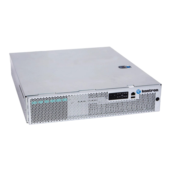
- Page 1 » Installation and Maintenance Guide « Kontron CG2300 Carrier Grade Server Document Revision 1.0 www.kontron.com...
- Page 2 All rights reserved. No part of this document may be reproduced, transmitted, transcribed, stored in a retrieval system, or translated into any language or computer language, in any form or by any means (electronic, mechanical, photocopying, recording, or otherwise), without the express written permission from Kontron. www.kontron.com...
- Page 3 Inter-integrated circuit bus International Electrotechnical Commission IEEE Institute of Electrical and Electronics Engineers IPMB Intelligent Platform Management Bus IPMI Intelligent Platform Management Initiative Interrupt request line KB, Kbyte Kilobyte – 1024 bytes Local Area Network Light-Emitting Diode Low Profile www.kontron.com...
- Page 4 Server Management Software Solid State Drive THOL Tested Hardware and Operating System List Technischer Uberwachungs-Verein (A safety testing laboratory with headquarters in Germany) Underwriters Laboratories, Inc. Universal Serial Bus Under-Voltage Volt Volt-amps (volts multiplied by amps) Volts alternating current www.kontron.com...
- Page 5 Installation and Maintenance Guide Volts direct current Verband Deutscher Electrotechniker (German Institute of Electrical Engineers) Video Graphics Array Voltage standby Watt Ω www.kontron.com...
-
Page 6: Table Of Contents
(I) Removing the Front Bezel ..........................37 5 Installation and Maintenance Tasks ....................39 Before Beginning These Tasks ..........................39 5.1.1 Tools and Supplies Needed ........................... 39 5.1.2 System References ............................39 Tasks with the Chassis Cover Removed ........................39 5.2.1 Configuring Memory DIMMs .......................... 39 www.kontron.com... - Page 7 (RI) Re-Installing the SuperCap Battery Backup ....................85 6.11 (RJ) Re-Installing the Processor Air Duct ......................86 6.12 (RK) Re-Installing a Riser Card Assembly ......................87 6.12.1 Re-Installing the Left Riser Card Assembly ....................87 6.12.2 Re-Installing the Right Riser Card Assembly ....................88 www.kontron.com...
- Page 8 System Boots When Installing a PCI Card ....................103 8.5.10 Problems with Newly Installed Application Software ................103 8.5.11 Problems with Application Software that Ran Correctly Earlier ..............103 8.5.12 Devices are not Recognized under Device Manager (Windows*OS) ............104 www.kontron.com...
- Page 9 11 Appendix C: NEBS Considerations ....................122 12 Appendix D: Getting Help ......................123 12.1 World Wide Web ............................... 123 » Table of Figures « Figure 1: Removing the Drive Carrier ..........................17 Figure 2: Removing a Hard Drive ............................17 www.kontron.com...
- Page 10 Figure 31: Installing the RAID Controller Board ......................... 51 Figure 32: Setting Up the Battery Backup Assembly ......................52 Figure 33: Adding Riser Cards ............................. 53 Figure 34: Installing a PCIe Add-In Card in the Riser Card Assembly ................. 54 www.kontron.com...
- Page 11 Figure 62: Re-Installing the Right Riser Card Assembly ..................... 89 Figure 63: Re-Attaching the Chassis Cover ......................... 90 Figure 64: Bent Pin Example ............................... 99 Figure 65: Contact Shifted Sideways Example ........................99 Figure 66: DC Power Supply Input Connector ........................109 www.kontron.com...
- Page 12 Kontron were advised of the possibility of such claims prior to the purchase of the product or during any period since the date of its purchase.
-
Page 13: Information
The CG2300 server is designed to meet NEBS-3 and ETSI certification, which makes it suited for a host of applications in the telecom Central Office and industrial environment. The server is targeted to OSS (Operations System and Support), Billing, Provisioning, Softswitch, Media Server, Wireless and Unified Messaging, Call Center, and many other applications. -
Page 14: System Overview
CG2300 Carrier Grade Server Configuration Guide or to have as spares. Refer to the for a complete list of orderable spares and options. The Configuration Guide can be found on the Kontron Support Website at http://cbu.kontron.ca/ (CRMS - CG2300 - Ordering Guide). -
Page 15: Additional Information And Software
Additional Information and Software If you need more technical information or information about the accessories that can be used with this CG2300 server, refer to the Technical Product Specification (TPS) for the system and/or for the server board. The TPS documents are located on the Kontron support website at http://cbu.kontron.ca/... -
Page 16: Normal Maintenance Tasks
Normal Maintenance Tasks This chapter covers the tasks you will most likely and most often need to do on the CG2300 server. These tasks involve hot- swappable components only, so there is no need to power down the server or remove the system cover. -
Page 17: Installing A Hard Drive In A Carrier
2. If a drive is already installed (that is, if you are replacing the drive), remove it by unfastening the four screws that attach the drive to the drive carrier. (Figure 2, “A”) Set the screws aside for use with the new drive. 3. Lift the drive (or filler panel) out of the carrier. (“B”) Figure 2: Removing a Hard Drive www.kontron.com... -
Page 18: Figure 3: Installing A Hard Drive
Press the locking lever until it snaps shut and secures the drive in the slot. (Figure 4 “B”) If this is the last task you are doing, replace the front bezel. See (RA) in Chapter 6. Figure 4: Inserting a New Hard Drive into the Chassis www.kontron.com... -
Page 19: Replacing System Fans
Installation and Maintenance Guide Replacing System Fans The fan replacement spare kit for the CG2300 server contains six 80mm fans. Each fan module is exactly like the fans in the CG2300 Carrier Grade Server server, i.e., the bracket and plastic finger guard are attached. For ordering information, see the Configuration Guide . -
Page 20: Figure 5: Removing A Hot-Swappable Fan
6. If this is the last task you are performing, close the chassis cover by sliding it forward until it clicks into place. Replace the shipping screw, if used. www.kontron.com... -
Page 21: Disassembling Server Components
(A) Removing the Chassis Top Cover The CG2300 server must be operated with the top cover in place to ensure proper cooling. Always power down the system and remove the top cover to add or replace any components inside the chassis that are not hot-swappable. -
Page 22: B) Removing A Riser Card Assembly
1. Loosen the two blue captive retention screws (Figure 7, “A”) at the front of the riser assembly and the blue captive screw at the rear of the chassis (“B”). 2. Using the two blue touch points (“C”), lift the riser card assembly out of the chassis (“D”). www.kontron.com... -
Page 23: B2) Removing The Right Riser Card Assembly
Loosen the two blue captive retention screws (Figure 8, “A”) at the front of the riser assembly and the blue captive screw at the rear of the chassis (“B”). Using the two blue touch points (“C”), lift the riser card assembly out of the chassis (“D”). www.kontron.com... -
Page 24: C) Removing The Processor Air Duct
Before you can remove the processor air duct, you first need to power down the server and remove all peripheral devices and power cord(s) and then the chassis cover and right riser card assembly. For instructions, see (A and (B2) in Chapter 4. To remove the processor air duct, simply lift the air duct straight up out of the chassis. www.kontron.com... -
Page 25: D) Removing The Support Cross Bar
For instructions see (B), (C), and (F) in Chapter 4. To remove the support cross bar: Figure 10 shows the location of all the components that have to be removed in order to remove the support cross bar. www.kontron.com... -
Page 26: Figure 10: Disconnecting Components From The Support Cross Bar
1. Remove the small flat screws that fasten the cross bar to the sides of the chassis. There is one screw on the left side and two on the right side. (Figure 11) 2. Remove the support cross bar from the chassis and set it aside. (Figure 11) www.kontron.com... -
Page 27: E) Disconnecting Cables
Figure 11: Removing the Support Cross Bar from the Chassis (E) Disconnecting Cables Cables must be disconnected in order to do several different tasks inside the CG2300 server. Figure 12 and Table 1 show all of the cable connections in the system. -
Page 28: Figure 12: Cable Routing
Provides power to the baseboard and the (J9G1) power supply with the PS-ON signal 2. CPU 1 and DIMM Power Power Distribution Board 3.3V D2D (soldered) to Baseboard CPU_1_PWR Provides power for CPU 1 and the DIMMs (J8K2) associated with CPU 1 www.kontron.com... - Page 29 RAID controller board (for HDDs 4-5) 20. HSBP I2C/HDD LED SAS HDD Backplane Board HSBP I C (J2) to Baseboard HSBP I C (J1D3) and Connects the HDD HSBP (hot-swap Front Panel Board C-2-C (HDD-LED). backplane) board to the baseboard and www.kontron.com...
-
Page 30: E1) Disconnecting Baseboard Power Side Cables
. The CPU2 cable is routed through CPU_1_PWR, J8K2) another black insulator along the right chassis wall to a connector at the rear right side of the board, (CPU_1_PWR, J9A2). For the locations of these cables, see Figure 12 in this section (E). www.kontron.com... -
Page 31: Disconnecting Baseboard Signal Side Cables
FPB: the support cross bar and the components attached to it, the cable bundles in the cable bracket, and the cable bracket/fan cage. For instructions, see (D), (E1), and (G) in Chapter 4. SSI Front Panel Board Cable www.kontron.com... - Page 32 C/HDD LED cable from the SAS backplane, you must first remove the front bezel, the active HDD carriers from the drive bay, and the HSBP backplane and air duct from the SAS HDD drive bay assembly. For instructions, see (I) and (H) in Chapter 4. www.kontron.com...
- Page 33 Fan (Fans 1-2), Fan (Fans 3-4), Fan (Fans 5-6) cables, which each connect the FCB with a fan pair in the fan cage. For the location of the three fan pair connectors (J3A1, J6A1, J9A1) on the FCB, see Figure 43 in Section 5.2.17. These cables are connected mechanically on the fan pairs in the fan cage. www.kontron.com...
-
Page 34: F) Removing The Supercap Battery Backup
To remove the battery backup module: Loosen the captive screw that fastens the battery backup to the support cross bar. (Figure 14, “A”) Lift the assembly up and out of the chassis. (“B”) Figure 14: Removing the Battery Backup www.kontron.com... -
Page 35: G) Removing The Cable Bundle Bracket And Fan Cage
CAUTION: Before removing or replacing any of the boards on the CG2300 server, you must first take the server out of service, turn off all peripheral devices connected to the server, turn off the server by pressing the power button, and unplug the power cord(s) from the system and wall outlet. -
Page 36: Figure 15: Removing The Cover Plate
4. Lift the backplane board and HDD air duct assembly up to access the connectors on the back of the board. (Figure 16, “A”). 5. Disconnect the four cables attached to the backplane board (“B”). 6. Lift the backplane board and air duct up and out of the chassis. (“C”). www.kontron.com... -
Page 37: 4.10 (I) Removing The Front Bezel
NOTE: The system does not have to be powered down just to remove the front bezel. 1. Loosen the captive bezel retention screw on the right side of the bezel (Figure 17, “A”). 2. Rotate the bezel to the left to free it from the pins on the front panel, (“B”) and remove it. www.kontron.com... -
Page 38: Figure 17: Removing The Front Bezel
Installation and Maintenance Guide Figure 17: Removing the Front Bezel www.kontron.com... -
Page 39: Installation And Maintenance Tasks
This chapter covers separately-orderable components that you may want to add or replace in your Kontron CG2300 Carrier Grade Server. Most of these components can be ordered as accessories from Kontron and some are from third party vendors. For more... -
Page 40: Replacing Or Removing Memory Dimms
Replacing or Removing Memory DIMMs Before you can replace or remove memory DIMMs in the server, you first need to remove the chassis cover, the right-side riser card, and the processor air duct. For instructions, see (A), (B1), and (C) in Chapter 4. www.kontron.com... -
Page 41: Adding Or Replacing A Processor
CAUTION: The processor must be appropriate: Severe damage to the server board may occur if a processor that is inappropriate for the server is installed. Refer to the Configuration Guide located on the support web page http://cbu.kontron.ca. (CRMS – CG2300 - Ordering Guide). -
Page 42: Figure 19: Using The Insertion-Removal Tool To Handle Processors
Keep part of your body (hand, etc.) in contact with the metal chassis to dissipate the static charge while handling the processor. » Avoid moving around unnecessarily. » Use a ground strap attached to the front panel (with the bezel removed.) www.kontron.com... -
Page 43: Figure 20: Cautions For Handling Processors
Do not force the heat sink. Doing so could damage the processor or the socket contacts. NOTE Figure 21: Removing the Heat Sink Removing a Processor The procedures that follow cover the steps for removing an old processor out of its socket on the server board. Opening the Socket www.kontron.com... -
Page 44: Figure 22: Using The Socket Levers
: Follow the ESD precautions covered in Appendix A: Safety Information”. NOTE Take the processor out of its packaging and remove the protective shipping cover by grasping the cover tab and pulling it away from processor load plate. Store the protective cover for future use. (Figure 24) www.kontron.com... -
Page 45: Figure 24: Removing The Shipping Cover
Press straight down using the tool button. A click indicates that the processor is loaded into the socket. Or if not using the tools: Orient the processor with the socket so that the processor cutouts match the socket notches. (Figure 25, “A”) Gently place the processor in the socket. (“B”) www.kontron.com... -
Page 46: Figure 25: Manually Installing The Processor In The Socket
When the load plate comes down and the lever is latched, the socket cover pops off. Save it for future use if the processor is removed from the socket or for protection if the server is moved or shipped. (Figure 27 “A” and “B”) www.kontron.com... -
Page 47: Installing A Heat Sink
Gradually and equally tighten each captive screw in diagonal order until each one is firmly tightened. See Figure 28 for the order. CAUTION: the torque spec for these screws is 8 inch pounds. Be careful not to exceed it. www.kontron.com... -
Page 48: Configuring Jumpers On The Server Board
This section shows the jumper blocks available and what they do. For detailed information about using these jumpers, see Sections 7.3 through 7.7. Pin 1 on each jumper block is identified by this symbol on the silkscreen: ▼ Figure 29 shows the jumper blocks. www.kontron.com... -
Page 49: Figure 29: Jumper Blocks (J1E2, J1E6, J2J2, J1E4, J1E3)
Pins 2 - 3 should not be connected for normal operation. Intel® Server Board S2600CW2SK See Section 9.1, “BIOS Defaults (CMOS Clear) and Password Reset Usage Procedure” in the Family TPS on the Kontron Support website for more information about the recovery features. www.kontron.com... -
Page 50: Installing A Hardware Raid Controller
5.2.7 Installing a Hardware RAID Controller Hard disk drives are supported with SAS software RAID 0/1/10 on the CG2300 server by default. Hardware RAID support requires a separately-orderable SAS hardware RAID controller, which is described in this section. : The components used as examples in this section are from the Intel® RS3DC080 hardware. -
Page 51: Installing The Supercap Battery Backup Module
AXXRMFBU4). For more information about the battery backup module, see the located on the Kontron support website at http://cbu.kontron.ca. (CRMS – CG2300 – Ordering Guide.) Before you can install the battery backup module, you need to remove the chassis cover and left riser card assembly. (That is, if they haven’t already been removed for installing the hardware RAID controller board). -
Page 52: Installing A Pcie Riser Card
The S2600CW2SK server board has two riser slots capable of supporting riser cards on the right side and left side of the chassis. Baseboard PCIe slot 2 (left side) and PCIe slot 6 (right side) support the riser cards in the CG2300 system. -
Page 53: Figure 33: Adding Riser Cards
CAUTION: Before removing or replacing any of the boards on the CG2300 server, you must first take the server out of service, turn off all peripheral devices connected to the server, turn off the server by pressing the power button, and unplug the power cord(s) from the system and wall outlet. -
Page 54: Installing Pcie Add-In Cards
Fasten the add-in card to the riser card assembly bracket using the rear retention screw. (“D”) For full-length cards, also secure the card in the grooves at the slot level on the retainer bracket and tighten the blue captive thumb screw. (“D”) Figure 34: Installing a PCIe Add-In Card in the Riser Card Assembly www.kontron.com... -
Page 55: Installing The Rmm4 Lite Key
5.2.11 Installing the RMM4 Lite Key The Remote Management Module (RMM) solution for the CG2300 server uses RMM4 in the iBMC on the S2600CW2SK server board. Before you can install the RMM4Lite key, you must first remove the chassis cover and the left riser card assembly. For instructions, see (A) and (B1) in Chapter 4. -
Page 56: Installing An M.2 Storage Drive
Connect the M.2 card to the header on the baseboard near the CMOS battery. (Figure 37, “A”) Seat the other end of the M.2 card around the post on the baseboard. Secure the M.2 card by fastening the screw in the post. (“B”) www.kontron.com... -
Page 57: Installing An Eusb Module
Before you can install an eUSB module, you must first remove the chassis cover, the left riser card assembly, and the hardware RAID backup battery assembly. For instructions, see (A), (B1), and (F) in Chapter 4. To install the eUSB module: Locate the standoff and connector on the baseboard. (Figure 38) www.kontron.com... -
Page 58: Figure 38: Installing An Eusb Flash Module On The Server Board
Re-install the left riser card assembly, the battery backup assembly, and the chassis cover. For instructions, see (RK), (RI), and (RL) in Chapter 6. If this is the last task you are performing, plug in the power cord(s) and re-attach any peripheral devices. www.kontron.com... -
Page 59: Replacing The Front Panel Board
Front panel board USB cable connector (J4) CAUTION: Before replacing any of the boards on the CG2300 server, you must first take the server out of service, turn off all peripheral devices connected to the server, turn off the server by pressing the power button, and unplug the power cord(s) from the system and wall outlet. -
Page 60: Figure 40: Removing The Front Panel Board From The Chassis
(Figure 41 “A” and “B”). 2. Replace and tighten the screws on the board to secure the board to the front panel shelf bracket. (“C”) www.kontron.com... -
Page 61: Figure 41: Installing The New Fp Board
4. Re-install the fan cage, the baseboard power cables, the support cross bar, and the chassis cover. For instructions, see (RC), (RG), (RH), and (RL). 5. If this is the last task you are performing inside the chassis, plug in the power cord(s) and re-attach any peripheral devices. www.kontron.com... -
Page 62: Replacing The Led/Switch Board
Replacing the Telco Alarms Module (TAM) Board The TAM board is on the right side of the CG2300 server chassis floor, just below the front panel. Before you can replace the TAM board, you must first remove the chassis cover, the support cross bar, the baseboard power cables, and the fan cage. (You do not have to remove the front panel board in order to access the TAM board). -
Page 63: Replacing The Fan Control Board (Fcb)
The fan control functions are controlled by the fan controller IC. This controller monitors the “Fan Present” signals from each of the fan positions, drives the “Fan PWM” signals, monitors the “Fan Tach” signals, and drives the “Fan Fail” signals. Fan speed is www.kontron.com... - Page 64 Unfasten the five screws on the fan control board that fasten it to the chassis floor. See Figure 43 for the locations of these screws. Save the screws to use when installing the new fan control board. Lift the fan control board out of the chassis. www.kontron.com...
-
Page 65: Figure 43: Fan Control Board Layout
3. Re-install the fan cage, the baseboard power cables, the support cross bar, and the chassis cover. For instructions, see (RC), (RG), (RH), and (RJ) in Chapter 6. 4. If this is the last task you are performing inside the server chassis, plug in the power cord(s), and re-attach any peripheral devices. www.kontron.com... -
Page 66: Replacing The Power Distribution Board (Pdb)
CAUTION: Before replacing any of the boards on the CG2300 server, first take the server out of service, turn off all peripheral devices connected to the server, turn off the server by pressing the power button, and unplug the power cord(s) from the system and wall outlet. -
Page 67: Figure 44: Removing The Pdb From The Chassis
Installation and Maintenance Guide Figure 44: Removing the PDB from the Chassis Remove the bracket from the PDB and save it and the two screws for use with the new PDB. (Figure 45) Figure 45: Removing the PDB Mounting Bracket www.kontron.com... -
Page 68: Figure 46: Attaching The Pdb Mounting Bracket
Fasten the PDB bracket to the new PDB with the two screws reserved from removing the old PDB. (Figure 46) Figure 46: Attaching the PDB Mounting Bracket Place the PDB back into the chassis and fasten the bracket to the chassis floor with the remaining two screws. (Figure 47, “A” and “B”). www.kontron.com... -
Page 69: Figure 47: Installing The New Pdb In The Chassis
(RB), (RH) and (RL) in Chapter 6. Push the power supply module(s) back into place so they are mated with the PDB. If this is the last task you are performing inside the server chassis, plug in the power cord(s), and re-attach any peripheral devices. www.kontron.com... -
Page 70: Replacing The S2600Cw2Sk Server Board
CAUTION: Before replacing any of the boards on the CG2300 server, first take the server out of service, turn off all peripheral devices connected to the server, turn off the server by pressing the power button, and unplug the power cord(s) from the system and wall outlet. -
Page 71: Figure 48: Removing The Server Board
Figure 48: Removing the Server Board Installing the New Server Board 1. Set the replacement server board in place. Insert the rear edge of the board first and line up the I/O ports with the slots in the rear panel of the chassis. www.kontron.com... -
Page 72: Replacing The Sas Backplane
CAUTION: Before replacing any of the boards on the CG2300 server, first take the server out of service, turn off all peripheral devices connected to the server, turn off the server by pressing the power button, and unplug the power cord(s) from the system and wall outlet. -
Page 73: Figure 49: Removing The Air Duct From The Backplane Board
For instructions, see (RB) in Chapter 6. If this is the last task you are performing inside the server chassis, plug in the power cord(s), and re-attach any peripheral devices. Figure 50: Re-Attaching the Backplane Board to the Air Duct www.kontron.com... -
Page 74: Tasks With The Chassis Closed
Adding or Replacing Hard Disk Drives Up to six hot-swappable SAS hard disk drives can be installed in the CG2300 server. The drives go into carriers that connect to the SAS backplane board once the carriers with drives attached are inserted back into the drive bay slots. The CG2300 server ships with six drive carriers. -
Page 75: Figure 51: Removing The Psu Filler Panel
Insert the new power supply by pressing and holding the green safety lock downward (Figure 52, “A”) and using the handle to slide the power supply into the slot until it latches into place. (“B”) Figure 52: Installing a PSU in the Second Slot www.kontron.com... -
Page 76: Installing The Server In A Rack
The latest version of the Configuration Guide is located on the Kontron support website at http://cbu.kontron.ca. (CRMS – CG2300 - Ordering Guide). Installation instructions are included in each of the rack mounting kits. - Page 77 Temperature — The operating temperature of the server, when installed in an equipment rack, must not go below 5°C (41°F) or rise above 40°C (104°F) ). Extreme fluctuations in temperature can cause a variety of problems in the server. www.kontron.com...
-
Page 78: Reassembling Server Components
1. Insert the tabs on the left side of the bezel into the slots on the front panel of the chassis. 2. Move the bezel toward the right and align it on the front panel pins. (Figure 54, “A”) 3. Snap the bezel into place and tighten the retention screw to secure it. (“B”) www.kontron.com... -
Page 79: Rb) Re-Installing The Sas Hot-Swap Backplane (Hsbp) Board
There is also a black plastic air duct surrounding the drive bay on the right side and rear of the assembly. To re-install the SAS backplane board: Re-connect the four SAS HDD cables to the HSBP board. For instructions, see (RE) in Chapter 6. Re-install the SAS backplane board and air duct. (Figure 55, “A” and “B”). www.kontron.com... -
Page 80: Figure 55: Re-Installing The Backplane Board
Secure the six-slot HDD backplane in place by placing the cover plate over the HDD bay assembly, the backplane and the air duct. (Figure 56 “A” and “B”) Re-fasten the screw that holds the cover plate in place. ( “C”) www.kontron.com... -
Page 81: Rc) Re-Installing The Cable Bundle Bracket And Fan Cage
Because both of these components need to be removed and are fastened together, they are treated as one assembly. To re-install the cable bundle bracket and fan cage: Fasten the fan cage (with the cable bracket attached) to the chassis floor using the two screws set aside when it was removed. www.kontron.com... -
Page 82: Rd) Re-Connecting The Fan Control Cables
HDD carriers in the drive bay, and re-attach the front bezel. For instructions, see (RB) and (RA) here in Chapter 6. (RF) Re-Connecting the Baseboard Signal Cables Signal side cables connect to the baseboard on the left side. See Figure 12: Cable Routing” in (E) in Chapter 4. www.kontron.com... -
Page 83: Rg) Re-Connecting The Baseboard Power Cables
For the location of the connector on the baseboard, see Figure 12: Cable Routing” in (E) in Chapter 4. To reconnect the main power cable: Run the cable bundle across the cable bundle bracket and connect it to the baseboard. If present, re-cover with the black insulator covering. www.kontron.com... -
Page 84: Figure 57: Routing The Cpu Power Cables
1. Run the cable bundles across the cable bundle bracket and connect them to the baseboard. (Figure 57) 2. Re-cover the black insulator covering the CPU 1 and CPU 2 power cable bundles in the cable bracket (if present). Figure 57: Routing the CPU Power Cables www.kontron.com... -
Page 85: Rh) Re-Installing The Support Cross Bar
6.10 (RI) Re-Installing the SuperCap Battery Backup Re-installing the SuperCap battery backup module entails fastening it to the support cross bar. Figure 31 shows how the battery backup is connected to the hardware RAID controller and positioned on the support cross bar. www.kontron.com... -
Page 86: 6.11 (Rj) Re-Installing The Processor Air Duct
Place the processor air duct over the processor sockets and DIMMs. Align the front tabs with the captive screws on the support cross bar. (Figure 60) (The air duct is secured when the right riser card assembly is mounted on the support cross bar above it.) www.kontron.com... -
Page 87: Rk) Re-Installing A Riser Card Assembly
Position the riser front tabs over the holes on the PCI support cross bar. (Figure 61). Using the blue touch points on the top of the assembly (“A”), press down to mate the riser card with the header on the server board (“B”, slot 2 for the left-side riser) www.kontron.com... -
Page 88: Re-Installing The Right Riser Card Assembly
Position the riser front tabs over the holes on the PCI support cross bar (over the processor air duct). (Figure 62). Using the blue touch points on the top of the assembly (“A”), press down to mate the riser card with the header on the server board (“B”, slot 6 for the right-side riser) www.kontron.com... -
Page 89: Rl) Re-Installing The Chassis Cover
Starting from the rear of the chassis, align the tab on the rear right edge of the cover with the lock bracket on the outside of the rear panel and place the cover down over the chassis with the side edges outside the chassis walls. (Figure 63) www.kontron.com... -
Page 90: Figure 63: Re-Attaching The Chassis Cover
Replace the two shoulder screws (one on each side) to fasten the cover to the chassis frame. (“C”) Torque screws to 8 lb*in. Reconnect all peripheral devices and the power cord(s). CAUTION: This unit must have the cover installed when it is running to ensure proper cooling. www.kontron.com... -
Page 91: Server Utilities
Server Utilities Using the BIOS Setup Utility This section describes the BIOS Setup utility, which is used to change configuration values for the Kontron CG2300 Carrier Grade Server. The BIOS Setup can be run with or without an operating system present. -
Page 92: Upgrading The Bios
NOTE: In the unlikely event that a BIOS error occurs during the BIOS update process, a recovery process may need to be followed to return the system to service. See Section 1.4, “Additional Information and Software” for additional information. www.kontron.com... -
Page 93: Updating The System Firmware
WARNING system reboot. To update the CG2300 server firmware, follow the standard update procedure in the embedded EFI shell. : Components (e.g., BIOS, BMC, ME, SDR) can be updated individually as shown below, but upgrading the full package is NOTE recommended to avoid possibly running incompatible firmware components. -
Page 94: Set Bios To Default (Clearing The Cmos)
” jumper back to the default operating position (covering pins 1 and 2). 10. Re-attach the system top cover and plug in the AC power cord(s). 11. Power up the server. 12. The password is now cleared and can be reset by going into the BIOS setup. www.kontron.com... -
Page 95: Integrated Bmc Force Update Procedure
5. Re-connect the AC cord(s) and power up the server. 6. Boot to the EFI shell and update the ME firmware using the “MEComplete.cap” file with the following command: iflash32 /u /ni MEComplete.cap 7. Power down and unplug the AC power cord(s). www.kontron.com... -
Page 96: Bios Recovery Jumper
Remove the right-side, slot 5 riser assembly. For instructions, see “(B) Removing a Riser Card Assembly”. Remove the processor air duct. For instructions, see “(C) Removing the Processor Air Duct”. Locate the “BIOS Default” jumper (J2J2) as shown in Figure 29. www.kontron.com... - Page 97 If this happens, remove the power cord again, wait 30 seconds, and reconnect the power cord. Then, power up the system and proceed to the <F2> BIOS Setup utility to reset the settings. www.kontron.com...
-
Page 98: Troubleshooting
: There are two levels of inspection in this procedure and three different criteria for rejecting a socket. Before returning the NOTE CG2300 system to Kontron for RMA based on bent pins, be sure the socket you are examining meets the two-level rejection criteria in these instructions. -
Page 99: Resetting The System
Return the server board directly to Intel (high volume system integrators) » RMA the whole CG2300 server to Kontron (low volume users) Contact Technical Support to get an RMA number and specify that the issue was found in Section 8.1, “CPU Socket CG2300 Server Installation and Maintenance Guide Inspection”... -
Page 100: First Steps Checklist
Was the system power on/off switch on the front panel pressed to turn the server on (power on light should be lit)? » Are all integrated components from the tested components lists? Check the tested memory list and the supported hardware and operating system list. Go to http://www.kontron.com/products/systems/telecom-systems/cg2300- carrier-grade-rackmount-server.html for links to the tested component lists. Hardware Diagnostic Testing This section provides a more detailed approach to identifying a hardware problem and locating its source. -
Page 101: Confirming The Operating System Load
Remove all add-in cards and see if the video returns. If successful, re-insert the cards one at a time with a reboot between each addition. » Make sure the memory DIMMs comply with the system requirements. » Make sure the memory DIMMs have been populated according to the system requirements. www.kontron.com... -
Page 102: Characters Are Distorted Or Incorrect
Make sure the network cable is securely attached to the correct connector at the system back panel. » Try a different network cable. » Make sure the correct and the current drivers are being used. Go to http://www.kontron.com/products/systems/telecom-systems/cg2300-carrier-grade-rackmount-server.html for a link to the drivers. » Make sure the driver is loaded and the protocols are bound. -
Page 103: The (Nic) Controller Stopped Working When An Add-In Adapter Was Installed
The (NIC) Controller Stopped Working When an Add-in Adapter was Installed » Make sure the cable is connected to the port from the onboard network controller. » Make sure the BIOS is current. Go to http://www.kontron.com/products/systems/telecom-systems/cg2300-carrier- grade-rackmount-server.html for a link to the current version. » Try reseating the add-in adapter. -
Page 104: Devices Are Not Recognized Under Device Manager (Windows*Os)
The Windows* operating systems do not include all of the drivers for the Intel chipsets, onboard NICs, and other components. ® Check the Kontron Deployment CD that came with the server or go to http://www.kontron.com/products/systems/telecom- systems/cg2300-carrier-grade-rackmount-server.html for a link to the current drivers and chipset files. - Page 105 Issue the appropriate hex IPMI “Chassis Identify” value. The ID LED will either blink for 15 seconds and turn off or will blink indefinitely until the hex IPMI “Chassis Identify” value is re-issued to turn it off. System Status LED The bicolor (green/amber) System Status LED www.kontron.com...
- Page 106 This does not apply to non-redundant systems. (NOTE: This state also occurs when power is first applied to the system. This indicates the BMC is booting) Power off, if no degraded, non-critical, critical, or non- recoverable conditions exist. Not ready www.kontron.com...
-
Page 107: Post Error Beep Codes
VR controller DC power on sequence was not completed in time 1-5-1-4 Power supply status The system does not power on or unexpectedly powers off and a Power Supply Unit (PSU) is present that is an incompatible model with the other PSU in the system. www.kontron.com... -
Page 108: Appendix A: Safety Information
To ensure EMC (Electromagnetic Compatibility) compliance with your local regional rules and regulations, the final configuration of your end system product may require additional EMC compliance testing. For more information, please contact your local Kontron Representative. See Appendix B, “Regulatory and Certification Information”... -
Page 109: If Dc Power Supplies Are Installed
The DC power supply module input mating connector shown in Figure 67 provides the -48V input power connection to the system. The input wiring connections are shown in the table in Figure 67. This mating connector (Positronic PLA03F7050/AA) and 3x gauge-16 pins (Positronic FC112N2/AA-14) come delivered with each DC power supply module. www.kontron.com... -
Page 110: Dc Power Supply Earth Grounding Studs On Chassis
The rack must also include ventilation sufficient to exhaust a maximum of 1023 BTUs (British Thermal Units) per hour for the server. The rack selected and the ventilation provided must be suitable to the environment in which the server will be used. www.kontron.com... -
Page 111: Safety Cautions
Contact should be made with care. Consider wearing protective gloves. Danger of explosion if the battery is incorrectly replaced. Replace only with the same or equivalent type recommended by the equipment manufacturer. Dispose of used batteries according to manufacturer’s instructions. www.kontron.com... -
Page 112: Wichtige Sicherheitshinweise
Nachdem Sie die oben erwähnten ersten sechs SICHERHEITSSCHRITTE durchgeführt haben, können Sie die Abdeckung abnehmen, indem Sie: 1. Öffnen und entfernen Sie die Verschlußeinrichtung (Padlock) auf der Rückseite des Systems, falls eine Verschlußeinrichtung installiert ist. 2. Entfernen Sie alle Schrauben der Gehäuseabdeckung. 3. Nehmen Sie die Abdeckung ab. www.kontron.com... -
Page 113: Consignes De Sécurité
Lisez attention toutes les consignes de sécurité et les mises en garde indiquées dans ce document avant de suivre toute instruction. Le bloc d’alimentation de ce produit ne contient aucune pièce pouvant être réparée par l'utilisateur. Ce produit peut contenir plus d’un bloc d'alimentation. Veuillez contacter un technicien qualifié en cas de problème. www.kontron.com... - Page 114 Danger d’explosion si la batterie n’est pas remontée correctement. Remplacer uniquement avec une batterie du même type ou d’un type équivalent recommandé par le fabricant. Disposez des piles usées selon les instructions du fabricant. www.kontron.com...
-
Page 115: Instrucciones De Seguridad Importantes
6. No ponga en marcha el sistema si se han extraído las tapas del chasis. Después de completar las seis instrucciones de SEGURIDAD mencionadas, ya puede extraer las tapas del sistema. Para ello: 1. Desbloquee y extraiga el bloqueo de seguridad de la parte posterior del sistema, si se ha instalado uno. www.kontron.com... - Page 116 Non modificare o utilizzare il cavo di alimentazione in c.a. fornito dal produttore, se non corrisponde esattamente al tipo richiesto. Ad ogni fonte di alimentazione corrisponde un cavo di alimentazione in c.a. separato. www.kontron.com...
- Page 117 Pulita e libera da particelle in sospensione (a parte la normale polvere presente nell’ambiente). » Ben ventilata e lontana da fonti di calore, compresa la luce solare diretta. » Al riparo da urti e lontana da fonti di vibrazione. www.kontron.com...
- Page 118 In aree soggette a temporali, è consigliabile collegare il sistema ad un limitatore di corrente. In caso di temporali, scollegare le linee di comunicazione dal modem. » Dotata di una presa a muro correttamente installata. » Dotata di spazio sufficiente ad accedere ai cavi di alimentazione, i quail rappresentano il mezzo principale di scollegamento del sistema. www.kontron.com...
-
Page 119: 10 Appendix B: Regulatory And Certification Information
GOST R Approval Emissions and Immunity (Russia) » KCC Approval (Korea) » CCC Certification (China) 10.1.3 Certifications/Registrations/Declarations » UL Listing (US/Canada) » CE Declaration of Conformity (Europe) » FCC/ICES-003 Class A Verification Report (USA/Canada) » VCCI Certification (Japan) » C-Tick Declaration of Conformity (Australia) www.kontron.com... -
Page 120: 10.2 Electromagnetic Compatibility Notices
(2) this device must accept any interference received, including interference that may cause undesired operation. For questions related to the EMC performance of this product, contact: Kontron America, Inc. 14118 Stowe Drive Poway, CA 92064-7147 (888) 294-4558 This equipment has been tested and found to comply with the limits for a Class A digital device, pursuant to Part 15 of the FCC Rules. -
Page 121: Europe (Ce Declaration Of Conformity)
Peripheral Storage Devices must be a UL recognized or UL listed accessory and TUV or VDE licensed. Maximum power rating of any one device is 19 watts. Total server configuration is not to exceed the maximum loading conditions of the power supply. www.kontron.com... -
Page 122: 11 Appendix C: Nebs Considerations
Electric Code (NEC) applies, but is not suitable for installation in Outside Plant (OSP) installations. The Battery Return (BR) for the -48V DC powered CG2300 systems is suitable for installation as either Isolation DC return (DC-I) or Common DC return (DC-C). Where the CG2300 is installed with a common DC return, the ampacity of the conductor connecting the equipment frame to the battery return conductor shall be equal to or greater than 13 amps. -
Page 123: 12 Appendix D: Getting Help
12 Appendix D: Getting Help 12.1 World Wide Web Technicians and engineers from Kontron and/or its subsidiaries are available for technical support. We are committed to making our product easy to use and will help you use our products in your systems. - Page 124 Beijing 100176, P. R. China Tel.: + 49 821 40 860 Tel.: + 1 888 294 4558 Tel.: + 86 10 63751188 Fax: + 49 821 40 860 111 Fax: + 1 858 677 0898 Fax.: + 86 10 83682438 sales@kontron.com info@us.kontron.com info@kontron.cn www.kontron.com...
Need help?
Do you have a question about the CG2300 and is the answer not in the manual?
Questions and answers