Sign In
Upload
Manuals
Brands
Kontron Manuals
Server
CG2300
Kontron CG2300 Manuals
Manuals and User Guides for Kontron CG2300. We have
2
Kontron CG2300 manuals available for free PDF download: Installation And Maintenance Manual, Configuration Manual
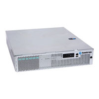
Kontron CG2300 Installation And Maintenance Manual (124 pages)
Carrier Grade Server
Brand:
Kontron
| Category:
Server
| Size: 7 MB
Table of Contents
Table of Contents
6
1 Information
13
Product Description
13
Purpose of this Document
13
2 System Overview
14
What the Server Includes
14
Product Accessories
14
Additional Information and Software
15
3 Normal Maintenance Tasks
16
Adding or Replacing Hot-Swappable Hard Disk Drives
16
Removing an HDD Carrier from the Chassis
16
Installing a Hard Drive in a Carrier
17
Figure 1: Removing the Drive Carrier
17
Figure 2: Removing a Hard Drive
17
Figure 3: Installing a Hard Drive
18
Figure 4: Inserting a New Hard Drive into the Chassis
18
Replacing System Fans
19
Figure 5: Removing a Hot-Swappable Fan
20
4 Disassembling Server Components
21
Before Beginning These Tasks
21
Tools and Supplies Needed
21
System References
21
A) Removing the Chassis Top Cover
21
B) Removing a Riser Card Assembly
22
B1) Removing the Left Riser Card Assembly
22
Figure 6: Removing the Cover
22
B2) Removing the Right Riser Card Assembly
23
Figure 7: Left Riser Card Assembly
23
C) Removing the Processor Air Duct
24
Figure 8: Right Riser Card Assembly
24
D) Removing the Support Cross Bar
25
Figure 9: Removing the Processor Air Duct
25
Figure 10: Disconnecting Components from the Support Cross Bar
26
E) Disconnecting Cables
27
Figure 11: Removing the Support Cross Bar from the Chassis
27
Figure 12: Cable Routing
28
E1) Disconnecting Baseboard Power Side Cables
30
Disconnecting Baseboard Signal Side Cables
31
Figure 13: Disconnecting the CPU Power Cables
31
F) Removing the Supercap Battery Backup
34
Figure 14: Removing the Battery Backup
34
G) Removing the Cable Bundle Bracket and Fan Cage
35
H) Removing the SAS Hot-Swap Backplane (HSBP) Board
35
Figure 15: Removing the Cover Plate
36
4.10 (I) Removing the Front Bezel
37
Figure 16: Removing the Backplane Board
37
Figure 17: Removing the Front Bezel
38
5 Installation and Maintenance Tasks
39
Before Beginning These Tasks
39
Tools and Supplies Needed
39
System References
39
Tasks with the Chassis Cover Removed
39
Configuring Memory Dimms
39
Installing Memory Dimms
39
Replacing or Removing Memory Dimms
40
Figure 18: Memory DIMM Installation
40
Adding or Replacing a Processor
41
Figure 19: Using the Insertion-Removal Tool to Handle Processors
42
Figure 20: Cautions for Handling Processors
43
Figure 21: Removing the Heat Sink
43
Figure 22: Using the Socket Levers
44
Figure 23: Opening the Load Plate
44
Figure 24: Removing the Shipping Cover
45
Figure 25: Manually Installing the Processor in the Socket
46
Figure 26: Closing the Processor Load Plate
46
Installing a Heat Sink
47
Figure 27: Closing the Last Socket Lever
47
Configuring Jumpers on the Server Board
48
Figure 28: Installing a Heat Sink
48
Figure 29: Jumper Blocks (J1E2, J1E6, J2J2, J1E4, J1E3)
49
Installing a Hardware RAID Controller
50
Figure 30: Hardware RAID Adapter Layout
50
Installing the Supercap Battery Backup Module
51
Figure 31: Installing the RAID Controller Board
51
Installing a Pcie Riser Card
52
Figure 32: Setting up the Battery Backup Assembly
52
Figure 33: Adding Riser Cards
53
Installing Pcie Add-In Cards
54
Figure 34: Installing a Pcie Add-In Card in the Riser Card Assembly
54
Installing the RMM4 Lite Key
55
Figure 35: Installing and Securing the Riser Card Assembly
55
Installing an M.2 Storage Drive
56
Figure 36: Installing the RMM4 Key
56
Installing an Eusb Module
57
Figure 37: Installing an M.2 Flash Drive on the Server Board
57
Figure 38: Installing an Eusb Flash Module on the Server Board
58
Replacing the Front Panel Board
59
Figure 39: Front Panel Board Connectors
59
Figure 40: Removing the Front Panel Board from the Chassis
60
Figure 41: Installing the New FP Board
61
Replacing the Led/Switch Board
62
Replacing the Telco Alarms Module (TAM) Board
62
Replacing the Fan Control Board (FCB)
63
Figure 42: Removing the TAM Board
63
Figure 43: Fan Control Board Layout
65
Replacing the Power Distribution Board (PDB)
66
Figure 44: Removing the PDB from the Chassis
67
Figure 45: Removing the PDB Mounting Bracket
67
Figure 46: Attaching the PDB Mounting Bracket
68
Figure 47: Installing the New PDB in the Chassis
69
Replacing the S2600CW2SK Server Board
70
Figure 48: Removing the Server Board
71
Replacing the SAS Backplane
72
Figure 49: Removing the Air Duct from the Backplane Board
73
Figure 50: Re-Attaching the Backplane Board to the Air Duct
73
Tasks with the Chassis Closed
74
Adding or Replacing Hard Disk Drives
74
Adding or Replacing a Power Supply Unit
74
Figure 51: Removing the PSU Filler Panel
75
Figure 52: Installing a PSU in the Second Slot
75
Installing the Server in a Rack
76
Figure 53: DC Power Supply Grounding
76
6 Reassembling Server Components
78
Before Beginning These Tasks
78
Tools and Supplies Needed
78
System References
78
RA) Re-Installing the Front Bezel
78
RB) Re-Installing the SAS Hot-Swap Backplane (HSBP) Board
79
Figure 54: Re-Attaching the Front Bezel
79
Figure 55: Re-Installing the Backplane Board
80
RC) Re-Installing the Cable Bundle Bracket and Fan Cage
81
Figure 56: Re-Attaching the Cover Plate
81
RD) Re-Connecting the Fan Control Cables
82
RE) Re-Connecting the HSBP Board Cables
82
RF) Re-Connecting the Baseboard Signal Cables
82
RG) Re-Connecting the Baseboard Power Cables
83
Figure 57: Routing the CPU Power Cables
84
RH) Re-Installing the Support Cross Bar
85
6.10 (RI) Re-Installing the Supercap Battery Backup
85
Figure 58: Re-Installing the Support Cross Bar
85
6.11 (RJ) Re-Installing the Processor Air Duct
86
Figure 59: Re-Installing the Battery Backup
86
RK) Re-Installing a Riser Card Assembly
87
Re-Installing the Left Riser Card Assembly
87
Figure 60: Re-Installing the Processor Air Duct
87
Re-Installing the Right Riser Card Assembly
88
Figure 61: Re-Installing the Left Riser Card Assembly
88
RL) Re-Installing the Chassis Cover
89
Figure 62: Re-Installing the Right Riser Card Assembly
89
Figure 63: Re-Attaching the Chassis Cover
90
7 Server Utilities
91
Using the BIOS Setup Utility
91
Using BIOS Setup
91
Starting Setup
91
If You Cannot Access Setup
91
Setup Menus
91
Upgrading the BIOS
92
Preparing for the Upgrade
92
Updating the System Firmware
93
BIOS Default and Password Reset Usage Procedure
93
Set BIOS to Default (Clearing the CMOS)
94
Clearing the Password
94
Integrated BMC Force Update Procedure
95
ME Force Update Jumper
95
BIOS Recovery Jumper
96
Restoring BIOS Default Settings
96
8 Troubleshooting
98
CPU Socket Inspection
98
First Level Inspection
98
Second Level Inspection
98
Resetting the System
99
Problems Following Initial System Installation
99
Figure 64: Bent Pin Example
99
Figure 65: Contact Shifted Sideways Example
99
First Steps Checklist
100
Hardware Diagnostic Testing
100
Verifying Proper Operation of Key System Lights
100
Confirming the Operating System Load
101
Specific Problems and Corrective Actions
101
Power Light Does Not Light
101
No Characters Appear on Screen
101
Characters Are Distorted or Incorrect
102
System Cooling Fans Do Not Rotate Properly
102
Cannot Connect to a Server
102
Diagnostics Pass but the Connection Fails
102
The (NIC) Controller Stopped Working When an Add-In Adapter was Installed
103
The Add-In Adapter Stopped Working Without Apparent Cause
103
System Boots When Installing a PCI Card
103
Problems with Newly Installed Application Software
103
Problems with Application Software that Ran Correctly Earlier
103
Devices Are Not Recognized under Device Manager (Windows*Os)
104
Hard Drive(S) Are Not Recognized
104
Light-Guided Diagnostics
104
Volt Stand-By LED
104
DIMM Fault Leds
104
System ID LED, System Status LED, and POST Code Diagnostic LED
104
POST Error Beep Codes
107
9 Appendix A: Safety Information
108
Emissions Disclaimer
108
Intended Uses
108
If AC Power Supplies Are Installed
108
If DC Power Supplies Are Installed
109
DC Power Supply Mating Connector
109
Figure 66: DC Power Supply Input Connector
109
DC Power Supply Earth Grounding Studs on Chassis
110
Overcurrent Protection
110
Temperature and Ventilation
110
Safety Cautions
111
Wichtige Sicherheitshinweise
112
Consignes de Sécurité
113
Instrucciones de Seguridad Importantes
115
10 Appendix B: Regulatory and Certification Information
119
10.1 Product Regulatory Compliance
119
Product Safety Compliance
119
Product EMC Compliance - Class a Compliance
119
Certifications/Registrations/Declarations
119
10.2 Electromagnetic Compatibility Notices
120
Fcc (Usa)
120
Industry Canada (ICES-003)
120
Europe (CE Declaration of Conformity)
121
VCCI (Japan)
121
BSMI (Taiwan)
121
Regulated Specified Components
121
11 Appendix C: NEBS Considerations
122
12 Appendix D: Getting Help
123
12.1 World Wide Web
123
Advertisement
Kontron CG2300 Configuration Manual (28 pages)
carrier grade
Brand:
Kontron
| Category:
Server
| Size: 1 MB
Table of Contents
Contact Information
2
Customer Service
2
Revision History
2
Table of Contents
4
Electrostatic Discharge
5
Limited Warranty
5
1 Introduction
6
Product Description
6
Purpose of this Document
6
General Flow for Configuring a CG2300 System
7
2 Ordering CG2300 Systems
8
CG2300 Base System
8
Select the Quantity and Type of Power Supply
10
Select Quantity and Type of Cpus
12
Heat Sink
13
Select Pcie Risers
13
Select RAID
15
Select Storage
16
Select Memory
16
Select Remote Management Module Option
17
Select System Mounting
18
3 Ordering CG2300 Serviceable Items
20
Figure 2: TMLCMOUNT21
22
Figure 3: Slide-In Rail-Type System
23
Figure 4: TMLPMOUNT41 Extender Kit
24
Figure 5: TMLPMOUNT51 Extender Kit
25
Figure 6: Two-Post MID-Mount in 23-Inch Rack
26
Figure 7: TMLPMOUNT41/51 - 2-Post
27
Advertisement
Related Products
Kontron CG2100
Kontron CG2200
Kontron CG2400
Kontron CG1200
Kontron CC2800
Kontron CP6006-SA
Kontron CP6006X-SA
Kontron ZINC CUBE C232
Kontron CP6923
Kontron CP3-BP8-M
Kontron Categories
Computer Hardware
Motherboard
Server
Industrial PC
Desktop
More Kontron Manuals
Login
Sign In
OR
Sign in with Facebook
Sign in with Google
Upload manual
Upload from disk
Upload from URL