
Related Manuals for Kontron KISS 4U KTC5520


Summary of Contents for Kontron KISS 4U KTC5520
- Page 1 KISS 4U KTC5520 User's Guide (Version 1.01) 0-0096-6800 If it’s embedded, it’s Kontron.
- Page 2 This page is intentionally left blank. www.kontron.com...
-
Page 3: Table Of Contents
1. Table of Contents KISS 4U KTC5520 – User's Guide (Version 1.01) 1. Table of Contents 1. Table of Contents ............................. 1 1.1. Table of Figures............................2 2. Introduction ............................4 2.1. Symbols used in this Manual........................5 3. Important Instructions..........................6 3.1. -
Page 4: Table Of Figures
Fig. 15: LAN2 and LAN1 LED on the front side ....................17 Fig. 16: SYSF2 and SYSF1 LED ........................17 Fig. 17: SYSID LED and SYSID button on the front side..................17 Fig. 18: Rear side of the KISS 4U KTC5520 platform....................20 Fig. 19: Grounding stud marked with PE symbol ....................21 www.kontron.com... - Page 5 Fig. 32: KISS 4U KTC5520, rear side without PE marked grounding stud..............31 Fig. 33: Detail: Filter mat holder on the front side of the KISS 4U KTC5520 platform ..........33 Fig. 34: Detail: without filter mat at the front side .................... 34 Fig.
-
Page 6: Introduction
Kontron Embedded Computers is aware of such errors or inaccuracies or that Kontron Embedded Computers is unaware of these as a result of gross negligence and Kontron Embedded Computers has failed to eliminate these errors or inaccuracies for this reason. Kontron Embedded Computers expressly informs the user that this manual only contains a general description of technical processes and instructions which may not be applicable in every individual case. -
Page 7: Symbols Used In This Manual
2. Introduction KISS 4U KTC5520 – User's Guide (Version 1.01) 2.1. Symbols used in this Manual Symbol Meaning This symbol indicates the danger of injury to the user or the risk of damage to the product if the corresponding warning notices are not observed. -
Page 8: Important Instructions
In the event of damage to the device caused by failure to observe the included document “General Safety Instructions for IT Equipment”, the hints in this manual or eventually the warning signs label on the device, Kontron Embedded Computers shall not be required to honor the warranty even during the warranty period and shall be exempted from the statutory accident liability obligation. -
Page 9: Safety Instructions
4. Safety Instructions KISS 4U KTC5520 – User's Guide (Version 1.01) 4. Safety Instructions Please consider the instructions described in the included “General Safety Instructions for IT Equipment”. 4.1. Operation of Laser Source Devices Fig. 1: Laser radiation warning label The optional CD ROM and DVD drives contain light-emitting diodes (classified in accordance with IEC 825-1:1993: LASER CLASS 1) and therefore must not be opened. -
Page 10: Electrostatic Discharge (Esd)
4. Safety Instructions KISS 4U KTC5520 – User's Guide (Version 1.01) 4.2. Electrostatic Discharge (ESD) A sudden discharge of electrostatic electricity can destroy static-sensitive devices or micro-circuitry. Proper packaging and grounding techniques are necessary precautions to prevent damage. Always take the following precautions: 1. -
Page 11: Fcc Statement
4. Safety Instructions KISS 4U KTC5520 – User's Guide (Version 1.01) 4.4. FCC Statement This equipment has been tested and found to comply with the limits for a Class A digital device, pursuant to Part 15 of the FCC Rules. These limits are designed to provide reasonable protection against harmful interference when the equipment is operated in commercial environment. -
Page 12: Scope Of Delivery
Optional Parts Slide Rails 5.1. Type Label and Product Identification The type label (product designation, serial number) and the inspection status label of your KISS 4U KTC5520 platform are located on the right side of the device. System Type Product Designation... -
Page 13: Product Description
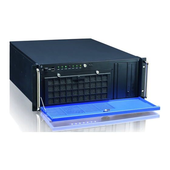
KISS 4U KTC5520 platform offer the superior qualities of a computer designed for operation in harsh industrial environment. The KISS 4U KTC5520 platform is designed to be installed in 19" racks. It may be also delivered as tower- and desktop version. - Page 14 KISS 4U KTC5520 – User's Guide (Version 1.01) The power button of the KISS 4U KTC5520 platform and a SYSID button are located on the front side behind the front access panel. On the front side are available a “power LED”, a “hard disk activity LED” and five LEDs for system monitoring.
- Page 15 6. Product Description KISS 4U KTC5520 – User's Guide (Version 1.01) Fig. 8: KISS 4U KTC5520, opened rackmount version 1 19" rack mountable bracket with handle (not 9 AC power supply unit available for tower and desktop version) 10 Grounding stud...
-
Page 16: Front Side
KISS 4U KTC5520 – User's Guide (Version 1.01) 6.1. Front Side Depending on the ordered system configuration, the KISS 4U KTC5520 platform will be delivered as rackmount or tower version. Fig. 9: Front side (rackmount version) with closed front access panel 1 19"... -
Page 17: Usb Interfaces
6.1.1. USB Interfaces The KISS 4U KTC5520 platform is equipped with two USB interfaces on the front side (see Fig. 11, pos. 13 and Fig. 12, pos. 2). You can connect different USB devices to these two USB 2.0 interface connectors. -
Page 18: Power Button
Fig. 13: LED indicators ans SYSID button on the front side Power- and HDD-LED 6.1.3.1. The Power LED marked “PWR” and the hard disk LED marked “HDD” of the KISS 4U KTC5520 platform are located on the front side, behind the front access door. 1 Power LED 2 HDD activity LED Fig. - Page 19 6. Product Description KISS 4U KTC5520 – User's Guide (Version 1.01) Gigabit-Ethernet (GbE LAN) LEDs 6.1.3.2. These two LEDs on the front side (see Fig. 13 and Fig. 15) and marked “LAN1” and “LAN2”, lights up/flashing, when Ethernet Link/Activity is established/detected.
-
Page 20: Front Access Panel
The securing lock mechanism (Fig. 9, pos. 5) located at the access panel allows you, if required, to protect your system from unauthorized use. When the access panel is locked, the cover of the KISS 4U KTC5520 system can not be removed, and the drives, the filter mat holder, the power and SYSID button are not accessible. -
Page 21: Drive Bays
Externally accessible 5.25" slim-line drive bay (shown with a slim-line DVD drive) One internal drive holder for a 2.5" or a 3.5" SATA HDD For KISS 4U KTC5520 system configurations with a disk subsystem with three HDDs, the drive bays L1 and L2 are occupied by this subsystem with removable HDDs. -
Page 22: Rear Side
KISS 4U KTC5520 – User's Guide (Version 1.01) 6.3. Rear Side Depending on the KISS 4U KTC5520 platform configuration ordered, the rear panel will have the external interfaces of the integrated server board, any additional interfaces, the power supply unit and the air exhaust openings. -
Page 23: Power Supply
The power supply is located on the rear side of the KISS 4U KTC5520 platform. On request, the KISS 4U KTC5520 platform can optionally be equipped with an AC wide rage PSU or a redundant AC wide rage PSU. The integrated power supply version also depends on the ordered system version and system configuration. The respective power supply version and the corresponding nominal voltage range can be found on the type label on the right side of the system. -
Page 24: Side View
Five M4 metric tapped holes are available at the left and right side of the unit (Fig. 21, pos. 2). These can be used in order to attach slide rails [not included; see chapter 10 “Slide Rails (Option)”] to the KISS 4U KTC5520 platform for system installation into a 19”... -
Page 25: Assembly, Disassembly
5. Attach the self adhesive rubber feet to the corresponding side of the chassis. If you operate the KISS 4U KTC5520 platform in vertical position, please observe that the system fans (slide-in module) must be to the lower front and the drives to the upper front of the system. -
Page 26: Fan Slide-In Module And Temperature Sensors
(Fig. 11, pos. 9 and Fig. 38, pos. 1). The fan slide-in module is mounted in a fan compartment on the front side of the system (Fig. 39, pos. 5). The system fans are temperature controlled via the temperature sensors installed in the KISS 4U KTC5520 platform. Thus, a reliable air circulation for optimal active cooling of the platform is guaranteed. -
Page 27: Accessing Internal Components
7. Assembly, Disassembly KISS 4U KTC5520 – User's Guide (Version 1.01) 7.4. Accessing Internal Components This section contains important information that you must read before accessing the internal components. You must follow these procedures properly when handling any boards or replacing the fan slide-in module. -
Page 28: Fig. 25: Loosening The Knurled Cover Fastening Screw On The Front Side
7. Assembly, Disassembly KISS 4U KTC5520 – User's Guide (Version 1.01) To install or remove an expansion card, perform the following steps: 1. Turn your system off and disconnect it from the AC main power supply. In order to remove the cover, unscrew the following knurled screws: the cover fastening screw (Fig. -
Page 29: Chassis
7. Assembly, Disassembly KISS 4U KTC5520 – User's Guide (Version 1.01) 3. Pull the cover out a little bit (Fig. 27) to release the cover centering and fixing brackets (Fig. 22, pos.3 and pos. 4) from the retaining brackets of the chassis (see Fig. 8, pos. 4). -
Page 30: Fig. 31: Opened Kiss 4U Ktc5520 Platform - Removing The Card Hold Down Brackets
(see Fig. 8, pos. 7) has to be removed (step 1 to 4). Fig. 31: Opened KISS 4U KTC5520 platform - removing the card hold down brackets 5. Loosen the internal and then the externally accessible fastening screw that secure the card hold down bracket for short expansion cards (see Fig. - Page 31 12. Close the KISS 4U KTC5520 platform and secure the cover with the captive knurled screws. The chassis of the KISS 4U KTC5520 platform with attached cover is properly closed only, if the following knurled screws are tightened: the cover fastening screw (Fig.
-
Page 32: Installation In A 19" Industrial Cabinet
The openings for air intake and exhaust on the device must not be obstructed by objects. Leave at least 5 cm (1.969 ") of free space in front and behind the KISS 4U KTC5520 platform to prevent the device from possibly overheating. -
Page 33: Starting Up
To connect the KISS 4U KTC5520 platform to an AC power supply, perform the following steps: 1. The KISS 4U KTC5520 systems with grounding studs marked with a PE symbol have to be grounded by establishing a large-area contact between the grounding stud (at the rear side) and an appropriate grounding connection point (see chapter 6.3.3 “Grounding Stud”, Fig. -
Page 34: Operating System And Hardware Component Drivers
(optional hardware components). Your computer is fully operational, when you switch it on for the first time. If you have ordered KISS 4U KTC5520 without a pre-installed operating system, you will need to install the operating system and the appropriate drivers for the system configuration you have ordered (optional hardware components) yourself. -
Page 35: Maintenance And Prevention
4 Fan slide-in module 5 Front access door Fig. 33: Detail: Filter mat holder on the front side of the KISS 4U KTC5520 platform To replace the filter mat, proceed as follows: 1. Open the front access panel (Fig. 33, pos. 5). -
Page 36: Fig. 34: Detail: Without Filter Mat At The Front Side
8. Secure the filter mat holder by tightening the knurled screws (Fig. 35, pos. 5) to the bolts with tapped holes (Fig. 34, pos. 1) of the fan slide-in module. Defective components may only be replaced by Kontron original spare parts. Air filter mat: part number: 1036-5058. -
Page 37: Replacing The System Fans
KISS 4U KTC5520 – User's Guide (Version 1.01) 9.2. Replacing the System Fans The operation of the KISS 4U KTC5520 system is permitted only with a functional fan slide-in module! Defective components may only be replaced by Kontron original spare parts: Part number of the fan slide-in module: 1036-5056. - Page 38 9. Maintenance and Prevention KISS 4U KTC5520 – User's Guide (Version 1.01) 5. Replace the fan slide-in module with a new functional module. 6. Install the filter mat holder (put aside in step 1) with the filter mat to the front side of the fan slide-in module, as described in chapter 9.1 “Cleaning the Filter Mat”...
-
Page 39: Replacing The Lithium Battery
4. Place a new lithium battery into the battery holder. 5. Pay attention to the polarity of the battery. 6. The lithium battery must be replaced with an identical battery or a battery type recommended by Kontron Embedded Computers (CR2032, 3V). -
Page 40: Slide Rails (Option)
KISS 4U KTC5520 – User's Guide (Version 1.01) 10. Slide Rails (Option) Kontron offers slide rails for installing the KISS 4U KTC5520 platform into a 19" industrial cabinet. These can be ordered separately. Fig. 40: Attaching the inner part to a KISS 4U KTC5520 platform Fig. -
Page 41: Technical Data
The corresponding “KISS 4U KTC5520 Systems - Configuration Guide” and the manual of the installed CPU board can be downloaded from our web site at www.kontron.com by selecting the product name. 11.1. Electrical Specifications The corresponding electrical specifications of your KISS 4U KTC5520 platform can be found on the type label. www.kontron.com... -
Page 42: Mechanical Specifications
11. Technical Data KISS 4U KTC5520 – User's Guide (Version 1.01) 11.2. Mechanical Specifications Dimensions KISS 4U KTC5520 Height 4U (177 mm) (6.968 ”) Width Front: 19” (482 mm); Chassis: 430 mm (16.9") Depth Chassis: 472.5 mm (18.6“) Weight (without Packaging) Approx. -
Page 43: Ce Directives And Standards
11. Technical Data KISS 4U KTC5520 – User's Guide (Version 1.01) 11.4. CE Directives and Standards CE Directive Elektrical Safety General Product Safety Directive (GPSD) 2001/95/EC Low Voltage Directive (LVD) 2006/95/EC Electromagnetic EMC Directive 2004/108/EC Compatibility (EMC) CE Marking CE Directive 93/68/EEC... -
Page 44: Standard Interfaces - Pin Assignments
12. Standard Interfaces – Pin Assignments KISS 4U KTC5520 – User's Guide (Version 1.01) 12. Standard Interfaces – Pin Assignments Low-active signals are indicated by a minus sign. 12.1.1. Serial Interface (RS232) Signal Name 9-pin D-SUB Connector (male) (Data Carrier Detect) -
Page 45: Usb Port
12. Standard Interfaces – Pin Assignments KISS 4U KTC5520 – User's Guide (Version 1.01) 12.1.3. USB Port Signal Name 4-pin USB Connector Type A Version 2.0 Data- Data+ 12.1.4. PS/2 Keyboard Connector Signal Name 6-pin Mini-DIN Connector Keyboard Data N.C. -
Page 46: Technical Support
• the serial number (SN) of the unit; the serial number can be found on the type label, placed on the right side of the system. Be ready to explain the nature of your problem to the service technician. If you have questions about Kontron Embedded Computers or our products and services, you may reach us at the aforementioned numbers, or at: www.kontron.com...
Need help?
Do you have a question about the KISS 4U KTC5520 and is the answer not in the manual?
Questions and answers