
Subscribe to Our Youtube Channel
Related Manuals for Kontron KISS Oil & Gas 2U


Summary of Contents for Kontron KISS Oil & Gas 2U
- Page 1 » User’s Guide « KISS Oil & Gas 2U - Rugged Server KTQ77/Flex User's Guide (Version 1.00) 930-0060-00 The pulse of innovation...
- Page 2 KISS Oil & Gas 2U User’s Manual (this page intentionally left blank) www.kontron.com...
-
Page 3: Table Of Contents
6.3.6. Audio Ports ............................23 6.3.7. Audio Connections ..........................23 6.3.8. Ground Stud ............................23 6.3.9. Chassis fans ............................23 6.3.10. Cable tie downs ..........................23 6.4. Rugged Features for Oil & Gas Customers ....................24 6.4.1. Expansion Card Brackets ........................24 www.kontron.com... - Page 4 13.4. USB 3.0 Port ............................. 49 13.5. USB 2.0 Port ............................. 49 14. Technical Support ............................. 50 14.1. Returning of Goods ..........................50 14.2. To request a Return Material Authorization (RMA) number ..............50 14.3. Contact and Delivery Address ......................... 51 www.kontron.com...
-
Page 5: Table Of Figures
Fig. 16: Block diagram for the Rugged 2U server ................26 Fig. 17: There are 5 threaded screw holes (M4) for attaching the optical slide rails ......27 Fig. 18: Kontron KTQ77/Flex Motherboard ................... 28 Fig. 19: System with cover closed ......................30 Fig. -
Page 6: Document Revision History
KISS Oil & Gas 2U User’s Manual 1.2. Document Revision History Revision Date Comment July 31, 2014 Preliminary version August 8, 2014 Updated pictures and name www.kontron.com... -
Page 7: Introduction
Kontron A m e r i c a . This manual is protected by copyright. All rights are reserved by Kontron A m e r i c a . Copies or partial copies of this manual or translations into other languages may not be produced, without the prior written consent of Kontron America. -
Page 8: Designed For The Oil And Gas Industry
Kontron has been designing and manufacturing embedded computer systems, subsystems and computer boards for the extreme needs of the military and industrial use for decades. By utilizing this expertise Kontron has developed the KISS Oil & Gas 2U, a rugged rackmount server designed to meet the needs for a tough, reliable server for the Oil &... -
Page 9: Important Instructions
In the event of damage to the device, which is caused by a failure to observe the instructions (specifically the safety instructions) in this manual and possibly on the device, Kontron America will not be required to honor the warranty, including during the warranty period, and will be exempt from legal liability for accidents. -
Page 10: Safety Instructions
» The device should only be operated in a horizontal position. » The device should only be maintained or repaired by specialists authorized by Kontron America, who are aware of the associated dangers. » The device should only be opened for the installation and removal of PCI-/PCIe x16 and 32-bit PCI expansion cards, in accordance with the description in this manual. -
Page 11: Operation Of Laser Source Devices
KISS Oil & Gas 2U User’s Manual » Only original accessories approved by Kontron America should be used. » It must be assumed that safe operation is no longer possible, when the device displays visible signs of damage, or when the device no longer works. In such cases, the device must be turned off and secured against unintentional operation. -
Page 12: Electrostatic Discharges (Esd)
Keep work area free of non-conductive materials such as ordinary plastic assembly aids and styrofoam. Use field service tools such as cutters, screwdrivers, and vacuum cleaners which are conductive. Always place drives and boards PCB-assembly-side down on the foam. www.kontron.com... -
Page 13: Instructions For The Lithium Battery
Danger of explosion when replacing with wrong type of battery. Replace the battery only with UL listed Lithium battery that has the same or equivalent type recommended by Kontron. Do not dispose of lithium batteries in general trash collection. Dispose of the battery according to the local regulations dealing with the disposal of these special materials, (e.g. -
Page 14: Scope Of Delivery
» Slim DVD +/- RW drive (installed) » Slide rails 5.1. Optional Components » Rubber feet (self-adhesive); Kontron part number 529-0043-00 » Replacement chassis filter: Kontron part number 409-0174-00 5.2. System Configuration Options » Up to 3x Hot-swap SATA drives »... -
Page 15: Rackmount To Desktop Conversion
You can very easily convert your system to a desktop version. To do this, unscrew the handles from on each side of the chassis by unscrewing the two screws on the back of each handle. To attach the rubber feet (optional), proceed as described in the “Attaching the Rubber Feet” chapter. www.kontron.com... -
Page 16: Product Description
KISS Oil & Gas 2U User’s Manual 6. Product Description The KISS Oil & Gas 2U is a scalable 2U (19") platform which is fitted with a Kontron designed motherboard. The robust design with excellent mechanical stability provides the 2U Rugged Rackmount Server platform with the necessary characteristics for a computer, suitable for use in the harsh field and control environments of the oil and gas industry. -
Page 17: Inside The 2U Rugged Server Chassis
If the top cover is removed from the 2U Rugged Server you can see the label on the right hand side which lists the Kontron serial number and model number for the system configuration. The drive bays near the front of the system are shock mounted, covered and secured to meet the rigorous demands of the Oil &... -
Page 18: From The Rear Panel
The system fans are located near the rear of the 2U Rugged Server. The power supply is also located in the rear right side of the unit with a fan for cooling. The motherboard with it’s box-like fan mounted on top is also located in the rear left side of the unit as are most of the I/O ports. www.kontron.com... -
Page 19: Front Of The System
The system must be connected to the appropriate power source, using the main power cable Hard drive activity This LED is orange when the hard disk is being accessed. LED (orange) Do not eject a drive, while the drive LED is lit or flashing. www.kontron.com... -
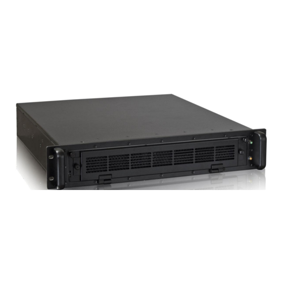
Page 20: Front Access Filter Cover
The chassis filter fits behind the filter cover. The filter cover has a ventilation grill. This chassis filter protects your system from dust and dirt (refer to “Cleaning the Chassis Filter” chapter). Fig. 9: Front of KISS Oil & Gas 2U (rackmount version) with the front access panel open www.kontron.com... -
Page 21: Inside The Front Panel
For this reason, ensure that there is easy access to the power cable, including its plug. 6.2.5. Slim DVD +/- RW The drive can be accessed to insert a DVD disk. www.kontron.com... -
Page 22: Usb Ports
2U Rugged Rackmount Server 2.5” or 3.25” HDD or 3x. External accessible shock mounted drive bays Solid State Drives 1x External accessible slim DVD +/- RW Optical Drive Fig. 11: Front of system behind drive cover showing optical and hard drives www.kontron.com... -
Page 23: Rear Panel
Since Kontron designs the motherboard and the system, the system has been optimized to ensure high MTBF. Fig. 12: Rear side of the KISS Oil & Gas 2U 6.3.1. -
Page 24: Vga Port
3x chassis fans are mounted to the back panel of the system. 6.3.10. Cable tie downs To ensure reliability in volatile environments cable tie downs can secure the cables to the system in either a Rackmount or desktop environment. www.kontron.com... -
Page 25: Rugged Features For Oil & Gas Customers
Fig. 13: The KISS Oil & Gas 2U has shock mounted drive bays 6.4.1. Expansion Card Brackets Adjustable expansion card hold down brackets protect customer added expansion cards. Fig. 14: The 2 expansion card brackets may be adjusted as needed www.kontron.com... -
Page 26: Memory Hold Down Bracket
6.4.4. Chassis filter The filter behind the front panel of the KISS Oil & Gas 2U extends to cover all areas of the front of the system that could be exposed to harsh environment, such as wind blowing dust. www.kontron.com... -
Page 27: System Block Diagram
Please note that the CPU selected by the customer to meet processing requirements is added to the motherboard. The CPU cooler fan is mounted on the motherboard to provide cooling for the CPU. An example of a memory card is shown. Drives and drive carrier bays are also shown. www.kontron.com... -
Page 28: Side View
Fig. 17: There are 5 threaded screw holes (M4) for attaching the optical slide rails 6.7. Integrated Motherboard KISS Oil & Gas 2U utilizes the Kontron KTQ77/Flex motherboard which supports the Intel® Q77 chipset and Generation Core™ i Series processors. -
Page 29: Expansion Slots
KISS Oil & Gas 2U User’s Manual Fig. 18: Kontron KTQ77/Flex Motherboard 6.7.1. Expansion Slots Depending on the configuration ordered, you can expand your system with full height, half length additional cards. System Integrated Board Expansion Cards 2U Rugged KTQ77/Flex... -
Page 30: Installation And Removal
KISS Oil & Gas 2U User’s Manual 7. Installation and Removal 7.1. Attaching the Optional Rubber Feet If the system is to be used as a desktop version, the optional rubber feet (order Kontron part number 529- 0043-00. To attach the rubber feet, proceed as follows: Before attaching the rubber feet, ensure that your system is switched off and disconnected from the power source. -
Page 31: Accessing Internal Components
The cover will be fixed to the chassis using two screws in the front side of the cover. The screws are fixed to a screw bracket visable when the cover is off. Screws Slide cover this way to remove Fig. 19: KISS Oil & Gas 2U with cover closed Fig. 20: Open to show Front Screw Fixing Bracket www.kontron.com... -
Page 32: Removing/Reattaching The Drive Cover
Please take good care of the screws while the cover is open. 8.2. Removing/Reattaching the Drive Cover To remove or reattach the drive cover unscrew the 6 screws shown. Fig. 21: 6 Screws in the Drive Cover Please take good care of the screws while the cover is open. www.kontron.com... -
Page 33: Installing/Removing Hot-Swap Drives
8.3. Installing/Removing Hot-Swap Drives There are three removable drive bays included in the KISS Oil & Gas Fig. 22: 2 of the 3 removable drives behind the drive cover Fig. 23: Gently pull open drive bay and remove/replace the drive. www.kontron.com... -
Page 34: Installing Expansion Cards
Adjust the expansion card hold down brackets to protect the cards. Close the device and secure the cover with the screws. Please read information provided by the manufacturer of any expansion cards before installing them or removing them from your system. www.kontron.com... - Page 35 KISS Oil & Gas 2U User’s Manual Fig. 24: : Inside of System showing Brackets that hold the Added Expansion Cards www.kontron.com...
-
Page 36: Adding System Memory
1. Unscrew memory protection bracket from the chassis side wall by unscrewing the two screws on the memory hold down bracket (see figure 25) 2. Insert and attach the memory cards to the motherboard. 3. Reattach the memory card hold down bracket. www.kontron.com... -
Page 37: Installation In A 19" Industrial Cabinet
Ensure that the air inlet and outlet openings are kept clear and free from any obstructions. Leave at least 5 cm (approx. 2”) of free space to the front and rear of the KISS Oil & Gas 2U when installing it from the 19" industrial cabinet, in order avoid possible overheating. www.kontron.com... - Page 38 The voltage feeds must not be overloaded. Adjust the cabling and the external overcharge protection to correspond with the electrical data indicated on the model and serial number label. The model and serial number label is located inside the unit on right side as well as on the bottom of the chassis. www.kontron.com...
-
Page 39: Starting Up
Plug the other end of the AC power cord into a corresponding power outlet. Turn the device ON via the power switch located at the front of the system behind the front chassis cover. Use a power cord suitable for the main power supply in your country. www.kontron.com... -
Page 40: Operating System And Hardware Component Drivers
Since Kontron works closely with Intel® at the board level some of the key Intel system management software and hardware functionality is enabled in the KTQ77/Flex motherboard and the KISS Oil & Gas 2U. Oil & Gas industry companies can benefit from remote system management and enhanced security. -
Page 41: Maintenance And Prevention
KISS Oil & Gas 2U User’s Manual 10. Maintenance and Prevention Kontron America systems only require minimal maintenance and care to keep them operating correctly. The harshness of the installation environment should be considered when determining the maintenance schedule. If the system will be subjected to frequent particulate matter, such as heavy dust, then maintenance should be more frequent. - Page 42 Remove the dirty chassis filter by lifting it off the front ventalation cover. It fits securely. There are no screws to hold the filter in place. Replace the dirty filter with a new filter (Kontron part 409-0174-00) or clean the existing filter. Clean the chassis filter as follows: »...
-
Page 43: Replacing The Lithium Battery
Re-position the expansion cards and re-attach the connecting cables. Close the device, as described in the “Installing Expansion Cards” chapter. Fig. 34: Kontron KTQ77/Flex Motherboard with memory marked out Do not dispose of lithium batteries in general trash collection. Dispose of the battery according to the local regulations dealing with the disposal of these special materials, (e.g. -
Page 44: Slide Rails (Option)
One pair of slide rails » One pair of short brackets for the front (with screws and washers) » One pair of long brackets for the back (with screws and washers) » 2x bar nut kits » 8x M4x6 flathead screws www.kontron.com... -
Page 45: Installing The Device In An Industrial Cabinet (Using Slide Rails)
Loosen the screws on the KISS Oil & Gas 2U chassis. » » Move the unit back and forward several times. » When the movement has improved, tighten the screws and move the unit the unit back and forward again. www.kontron.com... -
Page 46: Technical Data
Power-LED (green) (on the front) HDD-LED (orange) AC Power Plug 1x AC Wide Range (on the back) 12.3. Power Specification for Expansion Boards Power consumption per bay max. 25 Power specification (max. power values depending on customer- specific applications) (PCI) www.kontron.com... -
Page 47: Electrical Specifications
10,000 m (32,810 ft) Operating Shock 15 G, 11 ms duration, half sine 30 G., 11 ms duration, half sine Storage / Transit Shock 10 – 500 Hz, 5.0 G Operating Vibration 10 – 500 Hz, 5.0 G Storage / Transit Vibration www.kontron.com... -
Page 48: Ce Standards & Directives
EN 61000-6-4:2006 EUROPE Generic standards - Immunity for industrial environments (Immunity): EN 61000-6-2:2005 CE Directives General Product Safety Directive (GPSD) 2001/95/EC Electrical Safety Low Voltage Directive (LVD) 2006/95/EC ElectroMagnetic EMC Directive 2004/108/EC Compatibility (EMC) CE Marking Council Directive 93/68/EEC www.kontron.com... -
Page 49: Standard Ports - Pin Assignment
The pinout of Serial ports COM2, COM3 and COM4 is as follows: Pin Signal Name 9-pin D-SUB Connector DCD (Data Carrier Detect) (Data Set Ready) (Receive Data) (Request to Send) (Transmit Data) (Clear to Send) (Data Terminal Ready) (Ring Indicator) GND (Signal Ground) www.kontron.com... -
Page 50: Vga Port
Analog green output Analog blue output N.C. 5–8 +5 V (DDC) N.C. SDA (DDC) TTL HSync TTL VSync SCL (DDC) 13.4. USB 3.0 Port 13.5. USB 2.0 Port Pin Signal Name 4-pin USB Connector Type A Version 2.0 Data- Data+ www.kontron.com... -
Page 51: Technical Support
The model number of the device. This is based on the configuration your company has selected for the device. It is used in ordering the device from Kontron. The model number can be found on the name plate inside the top cover of the device. -
Page 52: Contact And Delivery Address
KISS Oil & Gas 2U User’s Manual 14.3. Contact and Delivery Address Kontron America 14118 Stowe Drive Poway, CA 92064-7147 Attn: RMA number Phone: 1-800-480-0044 Email: support@us.kontron.com CORPORATE OFFICES Asia Pacific Europe, Middle East & Africa North America Lise-Meitner-Straße 3-5 17 Building,Block #1, ABP.
Need help?
Do you have a question about the KISS Oil & Gas 2U and is the answer not in the manual?
Questions and answers