
Related Manuals for Kontron SYMKLOUD MS2900


Summary of Contents for Kontron SYMKLOUD MS2900
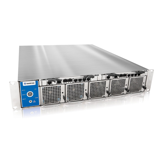
- Page 1 » User’s Guide « Kontron SYMKLOUD MS2900 Platform Document revision 1.5 www.kontron.com...
-
Page 2: Table Of Contents
Warranty ................................... 5 Technical Support ..............................5 2 About this Guide ..........................6 3 SYMKLOUD MS2900 Safety Information ................... 7 General Safety Warnings and Cautions ........................7 General Power Safety Warnings and Cautions ......................7 DC Power Supply Safety ............................8 Rack Installation Safety ............................ - Page 3 Platform Health Monitoring ......................... 31 Management Subsystems ............................31 5.2.1 Platform Management ..........................31 5.2.2 Cooling and Thermal Management ....................... 32 5.2.3 Power ................................34 Buttons, Connectors and LEDs ..........................35 5.3.1 LED Indicators ............................... 35 5.3.2 Cable Connections............................39 www.kontron.com...
- Page 4 Figure 14: Main Page Overview ............................30 Figure 15: Air Path Through the System ..........................33 Figure 16: Front and Rear Panel LEDs ..........................35 Figure 17: Rear Uplink Ports ..............................39 Figure 18: RJ-45 to DB-9 Console Adapter ......................... 39 www.kontron.com...
-
Page 5: User Information
Kontron will not be responsible for any defects or damages to other products not supplied by Kontron that are caused by a faulty Kontron product. -
Page 6: About This Guide
Environmental and regulatory specifications » System management – thermal, power, cables and connectors For more detailed information on these topics or additional features of the MS2900 platform, see all the available documentation and drivers on the Kontron web site http://www.kontron.com/ www.kontron.com... -
Page 7: Symkloud Ms2900 Safety Information
SYMKLOUD MS2900 Safety Information Caution! The SYMKLOUD MS2900 Platform is ESD sensitive equipment. Users must observe precautions for handling electrostatic discharge sensitive devices. Also review the following safety instructions before you handle the equipment. Although you may be using this guide or another resource as a reference, before working with SYMKLOUD products, WARNING pay close attention to the safety information in this section. -
Page 8: Dc Power Supply Safety
The grounded circuit conductor between the DC source and the grounding electrode conductor’s point of contact cannot be used for switching or disconnecting devices. Rack Installation Safety The following sections cover important guidelines and considerations for safely installing this equipment in a cabinet or rack. www.kontron.com... -
Page 9: Elevated Operating Ambient Temperature
Check the supply equipment nameplate ratings when addressing this concern. 3.4.5 Reliable Earth-Grounding Always maintain reliable grounding of rack-mounted equipment. Particular attention should be given to supply connections other than direct connections to the branch circuit (e.g. when using power strips). www.kontron.com... -
Page 10: The Symkloud Ms2900 Platform
The SYMKLOUD MS2900 Platform This chapter describes the main features of the Kontron MS2900 platform. It provides an overview and block diagram of the product, a list of the platform features, and also covers the mechanical, environmental, and regulatory specifications. -
Page 11: Feature Summary
EN 300 019 (meets) Telcordia GR-63 (designed to meet) Telcordia SR-3580 level 3 (designed to meet) Telcordia GR-1089 (designed to meet) EN 300 386 (meets) IEC/EN/CSA/UL 60950-1 (meets) FCC Part 15 (meets) (**Some limitations may apply, depending on the configuration) www.kontron.com... -
Page 12: Block Diagram
The modular design of the MS2900 platform makes all of the key system components hot-swappable, whether accessible from the front or rear external chassis panel. 4.3.1 Chassis Front Panel Figure 5 shows the features and accessible components on the MS2900 system front panel. www.kontron.com... -
Page 13: Figure 5: Front View
SFP+ stacking port (Switch/ShMC 2) (Marked ‘’1’’ on the Hub 2 faceplate) 10GbE SFP+ uplink port (Switch/ShMC 2) (Marked ‘’2’’ on the Hub 2 faceplate) Quad GbE RJ-45 ports (Switch/ShMC 2) (Marked “3”, “4”, “5”, and “6” on the Hub 2 faceplate) www.kontron.com... -
Page 14: Ms2900 Hot-Swappable Components
The control panel is the main health and status interface for the whole platform. Figure 6 shows the features on the control panel. Figure 6: System Control Panel Feature Description Power button Power LED (green) ESD connection Minor alarm LED (amber) Major alarm LED (red) Critical alarm LED (red) Chassis ID LED (blue) Chassis Power Button functionality www.kontron.com... - Page 15 Led OFF. Perform graceful shutdown of “Active” hub. Power State Nothing happens Nothing happens Transition *Note: The node’s BMC waits up to 5 minutes for the OS to shut down the CPU engine before forcing a power off. www.kontron.com...
-
Page 16: Msh8900 Hub Modules
Figure 7 shows the location on the chassis front panel of the hot-swappable hub modules. Figure 7: Hot-Swappable hub module NOTE: See the Kontron SYMKLOUD MSH8900 Hub Module User’s Guide on the Kontron web site at http://www.kontron.com/ for detailed information about this subsystem... -
Page 17: System Fans
LED. Figure 8 shows the location of the system fans on the chassis front panel. For information about cooling and thermal management within the MS2900 platform, see Section 5.2.2, “Cooling and Thermal Management“. Figure 8: Hot-Swappable System Fan Module www.kontron.com... -
Page 18: Chassis Rear Panel
: 1) Slots 7 and 9 have one 10GbE port, see lines 5 and 6 NOTES 2) Unpopulated slots ship with blank filler modules 3 & 4 AC or DC power supply unit (PSU 1 & 2) 5 & 6 Slots 7 & 9; with 3x GbE and 1x 10GbE ports www.kontron.com... -
Page 19: Processor Nodes
Figure 10 shows a hot-swappable processor node being removed from the chassis rear panel. Figure 10: Hot-Swappable Processor Nodes NOTE: See the Kontron SYMKLOUD MSP8000/MSP8001 Processor Node User’s Guide or the MSP8020 Processor Node User’s Guide on the Kontron web site at www.kontron.com... -
Page 20: Uplink/Stacking Module
Electrically hot swappable : When using optical SFP+ modules in Uplink Modules, the chassis alignment bracket may prevent easily pulling or closing NOTE the SFP+ release clamp. Pulling out the whole Uplink Module to release the SFP+ module is suggested. www.kontron.com... -
Page 21: Power Supply Units
NOTE: Read the power safety warnings in Sections 3.2 and 3.3 before handling the power supply units. Figure 12: Hot-Swappable Power Supplies See section 5.2.3 for information about the MS2900 platform power requirements. The key features of the power supply units are: » Hot-swappable » PMBus www.kontron.com... - Page 22 1080 1080 1080 1005 1300W 1300 1200 1200 1080 1069 1068 1500W 1500 1500 1500 1500 1500 1400 1100W 1080 1080 1080 1080 1080 1005 1300W 1300 1300 1300 1200 1200 1164 1500W 1500 1500 1500 1500 1500 1400 www.kontron.com...
- Page 23 User’s Guide Output Power (Watts) as a function of ambient temperature and DC input voltage (de-rating) Ambient Temperature (C) Vin(VAC) / T (°C) 40V-72V 1100W 1080 1080 1080 1080 1080 www.kontron.com...
- Page 24 105°C must be used. IEC60320-C14 1300W AC power A cable with C13 plug rated at supply module 105°C must be used. IEC60320-C14 1500W AC power A cable with C15 plug rated at supply module 105°C must be used. IEC60320-C16 www.kontron.com...
-
Page 25: Supported Operating Systems
The MS2900 platform supports most major OS distributions. Refer to the processor node User’s Guide that covers the processor node and CPU model used on your platform for a list of supported OS versions. Kontron continuously improves and extends the product documentation set for this platform. -
Page 26: Shipping Weights
2.95 DC power supply 1.34 2.95 Node carrier (bare sled - for unused slots) 0.36 0.80 Hub filler panel 0.14 Uplink module filler panel 0.04 0.09 Fan module 0.30 Generic DIMMs (2) 0.02 0.04 Solid State Drive (SSD) 0.15 www.kontron.com... -
Page 27: Rack Mounting Equipment
If that doesn’t work, you can remove the grounding lug by unscrewing the two fasteners and re-attaching the lug from the rear of the cabinet/rack once you have the chassis in place. See Figure 13. Figure 13: Attaching Slide Rails for Rear Mounting www.kontron.com... -
Page 28: Environmental Specifications
This product meets 8kV Contact, 15 kV Air Discharge using IEC61000-4-2 Test Method. Acoustic Designed to meet GR-63 and EN 300 753 This product is designed to meet China RoHS Phase 1 (self-declaration and labeling) RoHS This product complies with EU directive 2002/96/EC (WEEE) This product complies with RoHS directive 2011/65/EU www.kontron.com... -
Page 29: Regulatory Specifications
The presence of this logo on the product means it should not be disposed of as unsorted waste and must be collected separately. To find out how to properly dispose of this product, please contact your customer service representative. www.kontron.com... -
Page 30: Platform Management
System Maintenance (One-Click firmware upgrades) » Access to switch configuration page » Access to node KVM Kontron System Monitor User’s Guide NOTE: See the on the Kontron web site (www.kontron.com) for detailed information about this application Figure 14: Main Page Overview www.kontron.com... -
Page 31: Platform Health Monitoring
» Sensor Data Record (SDR) repository device functionality: the BMC supports storage and access of system SDRs » Sensor device and sensor scanning/monitoring: the BMC provides IPMI management of sensors and polls sensors to monitor and report system health. www.kontron.com... -
Page 32: Cooling And Thermal Management
Dynamic Host Configuration Protocol (DHCP): the BMC performs DHCP (supported on embedded NICs) » Embedded web server New Manageability Features The SYMKLOUD MS2900 platform also offers some new features: » Support for embedded web server UI in Basic Manageability feature set (i.e., fan monitoring, software upgrade, node health/presence) »... -
Page 33: Figure 15: Air Path Through The System
User’s Guide Figure 15: Air Path Through the System This cooling push configuration pressurizes the system. With this configuration, dust can only enter the system by the fan inlet. www.kontron.com... -
Page 34: Power
Subtotal Description Power (W) Quantity MSH8900 Hub (without SFP+ modules) MSU8700 Uplink Module (without SFP+ modules) SFP+ Optical Module 60x60x38 Fan Module MSP8020 Processor Node Module Total power consumption (W) Measured with a stressed transcoding application; 25°C ambient temperature www.kontron.com... -
Page 35: Buttons, Connectors And Leds
Buttons, Connectors and LEDs This section covers the user-accessible connectors, cable requirements, and LED definitions. 5.3.1 LED Indicators Figure 16 shows the locations of all MS2900 platform LEDs and the table explains the LED functions. Figure 16: Front and Rear Panel LEDs www.kontron.com... - Page 36 Hub hosts the inactive shelf manager = Blinking green Power/Active LED Payload power removed = Off Amber Hub “not healthy”, needs attention = On, amber (default) Hub transitioning when power button pressed (clean shutdown request) = Blinking, amber Status LED Hub operating under normal conditions = Off www.kontron.com...
- Page 37 Fault = On, amber LED2 Normal conditions, no fault = Off Processor Node Color(s) Description Red/Amber Node not healthy, needs attention = On, red Node in transition, power button pressed = Status LED Blinking, amber Node operating normally = Off www.kontron.com...
- Page 38 Regulation normal operation = On, green DC Output Both Yellow/Green Hot-Standby mode = Blinking, yellow 25%, green 75% Over temperature warning = Blinking, yellow 75%, green 25% Minor fan regulation error = Blinking, yellow 50%, green 50% Vsb – Standby Output (3V3) www.kontron.com...
-
Page 39: Cable Connections
MS2900 platform ships with an RJ-45 to DB-9 serial adapter (included in the box – see Figure 18). This adapter can be used with an RJ-45 cable to connect devices with a DB-9 serial port to the MS2900 via either hub RJ-45 console port (See Figure 5, “2” or “7”). Figure 18: RJ-45 to DB-9 Console Adapter www.kontron.com... - Page 40 Development Zone, Beijing 100176, P.R.China Tel.: +49 (0) 821 4086-0 Tel.: +1 888 294 4558 Tel.: + 86 10 63751188 Fax: +49 (0) 821 4086 111 Fax: +1 858 677 0898 Fax: + 86 10 83682438 info@kontron.com info@us.kontron.com info@kontron.cn www.kontron.com...
Need help?
Do you have a question about the SYMKLOUD MS2900 and is the answer not in the manual?
Questions and answers