
Related Manuals for Kontron CP6006-SA


Summary of Contents for Kontron CP6006-SA
- Page 1 USER GUIDE CP6006-SA User Guide, Rev. 0.5 Preliminary Doc. ID: [To be Determined] www.kontron.com // 1...
- Page 2 CP6006-SA – User Guide, Rev. 0.5 Preliminary This page has been intentionally left blank www.kontron.com // 2...
- Page 3 In cases of doubt, please contact Kontron. This user guide is protected by copyright. All rights are reserved by Kontron. No part of this document may be reproduced, transmitted, transcribed, stored in a retrieval system, or translated into any language or computer language, in any form or by any means (electronic, mechanical, photocopying, recording, or otherwise), without the express written permission of Kontron.
- Page 4 ENVIRONMENTAL DAMAGE (COLLECTIVELY, "HIGH RISK APPLICATIONS"). You understand and agree that your use of Kontron devices as a component in High Risk Applications is entirely at your risk. To minimize the risks associated with your products and applications, you should provide adequate design and operating safeguards.
- Page 5 If you have any difficulties using this user guide, discover an error, or just want to provide some feedback, contact Kontron support. Detail any errors you find. We will correct the errors or problems as soon as possible and post the revised user guide on our website.
-
Page 6: Symbols
CP6006-SA – User Guide, Rev. 0.5 Preliminary Symbols The following symbols may be used in this user guide DANGER indicates a hazardous situation which, if not avoided, will result in death or serious injury. WARNING indicates a hazardous situation which, if not avoided, could result in death or serious injury. -
Page 7: For Your Safety
Therefore, in the interest of your own safety and of the correct operation of your new Kontron product, you are requested to conform with the following guidelines. -
Page 8: Lithium Battery Precautions
General Instructions on Usage In order to maintain Kontron’s product warranty, this product must not be altered or modified in any way. Changes or modifications to the product, that are not explicitly approved by Kontron and described in this user guide or received from Kontron Support as a special handling instruction, will void your warranty. -
Page 9: Table Of Contents
CP6006-SA – User Guide, Rev. 0.5 Preliminary Table of Contents Symbols ..........................................6 For Your Safety ........................................7 High Voltage Safety Instructions .................................. 7 Special Handling and Unpacking Instruction ............................7 Lithium Battery Precautions ..................................8 General Instructions on Usage..................................8 Quality and Environmental Management .............................. - Page 10 CP6006-SA – User Guide, Rev. 0.5 Preliminary 2.7.11. High-Speed Serial Rear I/O Interconnection ..........................49 Configuration ...................................... 50 3.1. DIP Switch Configuration ..................................50 3.1.1. DIP Switch SW1 ....................................... 50 3.1.2. DIP Switch SW2 ..................................... 50 3.2. System Write Protection ..................................51 3.3.
- Page 11 CP6006-SA – User Guide, Rev. 0.5 Preliminary 8.3. Supported IPMI and ATCA Commands ............................. 73 8.3.1. Standard IPMI Commands ................................. 74 8.3.2. AdvancedTCA and AMC Commands..............................77 8.4. Firmware Identification ..................................78 8.4.1. Get Device ID Command ..................................78 8.4.2. Device Locator Record ..................................79 8.5.
-
Page 12: List Of Tables
Table 6: Watchdog and Temperature Status LEDs’ Functions ......................31 Table 7: IPMI and HS LEDs’ Functions ............................... 32 Table 8: General Purpose LEDs’ Functions on the CP6006-SA ......................33 Table 9: General Purpose LEDs’ Functions on the CP6006X-SA ...................... 33 Table 10: POST Code Sequence ................................... -
Page 13: List Of Figures
Figure 1: CP6006(X)-SA Functional Block Diagram ..........................16 Figure 2: 4 HP CP6006(X)-SA Front Panel ..............................17 Figure 3: 4 HP CP6006-SA Front Panel (Top View) ..........................18 Figure 4: 4 HP CP6006X-SA Front Panel (Top View) ..........................19 Figure 5: 4 HP CP6006(X)-SA Front Panel (Bottom View) ......................... 20 Figure 6: Serial Port Connect or J8 ................................ -
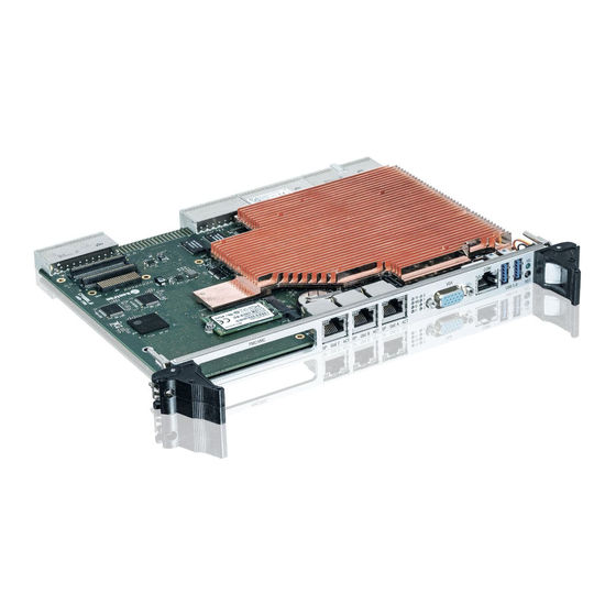
Page 14: 1/ Introduction
1/ Introduction 1.1. Board Overview CP6006-SA is a 6U server class CPU platform, based on the 14 nm Intel® Xeon® D-1500 processor with 2–16 cores options, with excellent performance-per-watt values. Its scalable power budget allows users to tailor the power dissipation to their requirements. CP6006-SA provides cooling mechanics for standard air cooled systems. -
Page 15: System Expansion Capabilities
The CP6006(X)-SA has a 3.3 V, PMC mezzanine interface configurable for 32-bit / 66 MHz PCI operation. This interface supports a wide range of PMC modules with PCI interface including all of Kontron’s PMC modules and provides an easy and flexible way to configure the CP6006(X)-SA for various application requirements. For information on the PMC interface, refer to Chapter 2.7.7, "PMC Interface". -
Page 16: Board Diagrams
CP6006-SA – User Guide, Rev. 0.5 Preliminary 1.3. Board Diagrams The following diagrams provide additional information concerning board functionality and component layout. 1.3.1. Functional Block Diagram Figure 1: CP6006(X)-SA Functional Block Diagram www.kontron.com // 16... -
Page 17: Front Panel
CP6006-SA – User Guide, Rev. 0.5 Preliminary 1.3.2. Front Panel Figure 2: 4 HP CP6006(X)-SA Front Panel IPMI LEDs I0/I1 (red/green): Indicate the software status of the IPMI controller System Status LEDs HS (blue): Hot Swap Status TH (red/green): Temperature Status... -
Page 18: Board Layout
CP6006-SA – User Guide, Rev. 0.5 Preliminary 1.3.3. Board Layout Figure 3: 4 HP CP6006-SA Front Panel (Top View) www.kontron.com // 18... -
Page 19: Figure 4: 4 Hp Cp6006X-Sa Front Panel (Top View)
CP6006-SA – User Guide, Rev. 0.5 Preliminary Figure 4: 4 HP CP6006X-SA Front Panel (Top View) www.kontron.com // 19... -
Page 20: Figure 5: 4 Hp Cp6006(X)-Sa Front Panel (Bottom View)
CP6006-SA – User Guide, Rev. 0.5 Preliminary Figure 5: 4 HP CP6006(X)-SA Front Panel (Bottom View) www.kontron.com // 20... -
Page 21: Technical Specification
CP6006-SA – User Guide, Rev. 0.5 Preliminary 1.4. Technical Specification Table 1: CP 6006(X)-SA Main Specifications Processor & Chipset Processsor The CP6006(X)-SA supports the following 4 generation processors: Intel® Xeon® Processor D-1500, integrating a PCH and a dual 10 GbE NIC. - Page 22 Socket for M.2 Solid State Drive (SSD) One standard SATA 6 Gb/s interface for the standard SATA connector SATA 3Gb/s: four ports (CP6006-SA) respectively two ports (CP6006X-SA) accessible via rear I/O High-performance RAID 0/1/5/10 functionality on all SATA ports www.kontron.com...
- Page 23 CP6006-SA – User Guide, Rev. 0.5 Preliminary Sockets Front Panel Connectors VGA: one 15-pin, D-Sub connector, J9 USB: two 4-pin, type A connectors, J6 and J7 Ethernet: three 8-pin, RJ-45 connectors, J10, J11 and J12 Serial port: one 8-pin, RJ-45 connector, J8 (COMA) ...
- Page 24 CP6006-SA – User Guide, Rev. 0.5 Preliminary IPMI IPMI Controller NXP® ARM7 microcontroller with 512 kB firmware flash and automatic rollback strategy The IPMI controller carries out IPMI commands such as monitoring several onboard temperature conditions, board voltages and the power supply status, and managing hot swap operations.
- Page 25 CP6006-SA – User Guide, Rev. 0.5 Preliminary Software (continued) IPMI Firmware IPMI firmware providing the following features: Keyboard Controller Style (KCS) interface Dual-port IPMB interface for out-of-band management and sensor monitoring IPMI over LAN (IOL) and Serial over LAN (SOL) support ...
-
Page 26: Standards (Preliminary; To Be Verified)
Boards without conformal coating must not be exposed to a change of temperature which can lead to condensation. Condensation may cause irreversible damage, especially when the board is powered up again. Kontron does not accept any responsibility for damage to products resulting from destructive environmental testing www.kontron.com... -
Page 27: Related Publications
CP6006-SA – User Guide, Rev. 0.5 Preliminary 1.6. Related Publications The following publications contain information relating to this product. Table 4: Related Publications Product Publication CompactPCI Systems PICMG 2.0, Rev. 3.0 CompactPCI Specification PICMG 2.16, Rev. 1.0 CompactPCI Packet Switching Backplane Specification PICMG 2.20, Rev. -
Page 28: 2/ Functional Description
CP6006-SA – User Guide, Rev. 0.5 Preliminary 2/ Functional Description 2.1. Processor The CP6006(X)-SA supports the Intel® XEON® D-1539 and the Intel® XEON® D-1548 processors. Table 5: Features of the Processors Supported on the CP6006(X)-SA FEATURE Intel® XEON® D-1539, 1.64 GHz Intel®... -
Page 29: Graphics Controller
CP6006-SA – User Guide, Rev. 0.5 Preliminary 2.1.1. Graphics Controller CP6006-SA provides a low-power graphic controller, SM750 LynxExp with video and 2D capability. It supports two independent display interfaces with a maximum resolution of 1920x1440 pixels. One of the graphic ports of the SM750 is for the DVI1/HDMI1 port at the rear IO, the other port is a combination of: VGA front or VGA rear or DVI2/HDMI2, which is user selectable via BIOS setting. -
Page 30: Flash Memory
CP6006-SA – User Guide, Rev. 0.5 Preliminary 2.5. Flash Memory The CP6006(X)-SA provides flash interfaces for the uEFI BIOS. 2.5.1. SPI Boot Flash for uEFI BIOS The CP6006(X)-SA provides two 16 MB SPI boot flashes for two separate uEFI BIOS images, a standard SPI boot flash and a recovery SPI boot flash. -
Page 31: Board Interfaces
CP6006-SA – User Guide, Rev. 0.5 Preliminary 2.7. Board Interfaces 2.7.1. Front Panel LEDs The CP6006(X)-SA provides three system status LEDs, one Hot Swap Status LED (HS LED), one temperature status LED (TH LED) and one Watchdog status LED (WD LED), as well as two IPMI LEDs (I0 and I1) and four General Purpose/POST code LEDs (LED3–0). -
Page 32: Table 7: Ipmi And Hs Leds' Functions
The General Purpose LEDs (LED3–0) are designed to indicate the boot-up POST code after which they are available to the application. If the LED3–0 are lit red during boot-up, a failure is indicated. In this event, please contact Kontron for further assistance. -
Page 33: Table 8: General Purpose Leds' Functions On The Cp6006-Sa
CP6006-SA – User Guide, Rev. 0.5 Preliminary Table 8: General Purpose LEDs’ Functions on the CP6006-SA COLOR FUNCTION FUNCTION DURING uEFI BIOS POST FUNCTION DURING BOOT-UP (if POST code config. is enabled) AFTER BOOT-UP LED3 Power failure green uEFI BIOS POST bit 3 and bit 7... -
Page 34: Usb Interfaces
CP6006-SA – User Guide, Rev. 0.5 Preliminary How to Read the 8-Bit POST Code Due to the fact that only 4 LEDs are available and 8 bits must be displayed, the POST code output is multiplexed on the General Purpose LEDs. -
Page 35: Serial Ports
The COMA and COMB ports provide maskable interrupt generation. The data transfer on the COM ports is up to 115.2 kbit/s. If RS-422 is required on the COMB port, please contact Kontron for further assistance. The serial port COMA is implemented as an 8-pin RJ-45 connector, J8. The following figure and table provide pinout information for the serial connector J8 (COMA). -
Page 36: Sata Interfaces
CP6006-SA – User Guide, Rev. 0.5 Preliminary 2.7.5.1. 10 Gigabit Ethernet Interfaces (CP6006X-SA) The CP6006X-SA supports two 10GBASE-KR Ethernet interfaces on the rear I/O using the Intel® SoC dual-port 10 Gigabit Ethernet controller. The following table indicates the 10 Gigabit Ethernet port mapping of the CP6006X-SA... -
Page 37: Xmc Interface
CP6006-SA – User Guide, Rev. 0.5 Preliminary 2.7.8. XMC Interface For easy and flexible configuration a standard XMC connector, J20, is available. The board uses one x8 PCI Express 2.0 interface operating at 5.0 GT/s and compliant with the ANSI/VITA 42.0 and ANSI/VITA 42.3 specifications. x8 PCI Express 3.0 operating at 8 GT/s is available on request. - Page 38 CP6006-SA – User Guide, Rev. 0.5 Preliminary 2.7.9.4. Hot Swap Support To ensure that a board may be removed and replaced in a working bus without disturbing the system, the following additional features are required: Power ramping Precharge ...
-
Page 39: Compactpci Connectors
CP6006-SA – User Guide, Rev. 0.5 Preliminary 2.7.10. CompactPCI Connectors Figure 7: Compact PCI Connectors The complete CompactPCI connector configuration comprises up to four standard connectors (2mm Hard Metric) designated as J1, J2, J3 and two high-speed serial ZDplus connectors, J4 and J41. -
Page 40: Table 17: Compactpci Bus Connector J1 System Slot Pinout
CP6006-SA – User Guide, Rev. 0.5 Preliminary 2.7.10.2. CompactPCI Connectors J1 and J2 Pinout The CP6006(X)-SA is provided with two 2 mm x 2 mm pitch female CompactPCI bus connectors, J1 and J2. Table 17: CompactPCI Bus Connector J1 System Slot Pinout... -
Page 41: Table 18: Compactpci Bus Connector J1 Peripheral Slot Pinout
CP6006-SA – User Guide, Rev. 0.5 Preliminary Table 18: CompactPCI Bus Connector J1 Peripheral Slot Pinout 3.3V V(I/O) 3.3V 3.3V 3.3V V(I/O) 3.3V 3.3V 3.3V IPMB SCL IPMB SDA V(I/O) 3.3V BDSEL# 14-12 Key Area 3.3V V(I/O) CPCI_Present# 3.3V RST#**... -
Page 42: Table 19: 64-Bit Compactpci Bus Connector J2 System Slot Pinout
CP6006-SA – User Guide, Rev. 0.5 Preliminary Table 19: 64-bit CompactPCI Bus Connector J2 System Slot Pinout CLK6 CLK5 IPMB2_SDA IPMB2_SCL IPMB2_Alert PRST# REQ6# GNT6# DEG# FAL# REQ5# GNT5# AD[35] AD[34] AD[33] AD[32] AD[38] V(I/O) AD[37] AD[36] AD[42] AD[41] AD[40]... -
Page 43: Table 20: 64-Bit Compactpci Bus Connector J2 Peripheral Slot Pinout
CP6006-SA – User Guide, Rev. 0.5 Preliminary Table 20: 64-bit CompactPCI Bus Connector J2 Peripheral Slot Pinout IPMB2_SDA IPMB2_SCL IPMB2_Alert DEG# FAL# V(I/O) V(I/O) V(I/O) V(I/O) V(I/O) V(I/O) SYSEN# A * indicates that the signal normally present at this pin is disconnected from the CompactPCI bus when the CP6006(X)-SA is inserted in a peripheral slot. -
Page 44: Table 21: 64-Bit Compactpci Rear I/O Connector J3 Pinout
CP6006-SA – User Guide, Rev. 0.5 Preliminary Table 21: 64-bit CompactPCI Rear I/O Connector J3 Pinout RIO_VCC RIO_VCC RIO_3.3V RIO_+12V RIO_-12V LPa_DA+ LPa_DA- LPa_DC+ LPa_DC- LPa_DB+ LPa_DB- LPa_DD+ LPa_DD- LPb_DA+ LPb_DA- LPb_DC+ LPb_DC- LPb_DB+ LPb_DB- LPb_DD+ LPb_DD- LPa:LINK LPb:LINK LPab:CT1... -
Page 45: Table 22: Compactpci Rear I/O Connector J3 Signals
CP6006-SA – User Guide, Rev. 0.5 Preliminary Table 22: CompactPCI Rear I/O Connector J3 Signals SIGNAL DESCRIPTION COMA signaling (RS-232) COMB signaling (RS-232) Graphic signaling USB0 to USB3 USB port signaling SPEAKER Standard PC speaker Fan speed sensoring DEBUG Debug output... -
Page 46: Table 23: Compactpci Rear I/O Connector J5 Pinout
CP6006-SA – User Guide, Rev. 0.5 Preliminary Table 23: CompactPCI Rear I/O Connector J5 Pinout GPI3 PWM1:OUT PWM2:OUT BATT (3.0V) Reserved Reserved Reserved SYS_WP# GPO0 Reserved GPO1 Reserved Reserved Reserved HDMI2:D0+ HDMI2:D0- HDMI2:D2+ HDMI2:D2- HDMI2:D1+ HDMI2:D1- HDMI2:HPDET GPO2 GPO3 HDMI2:CLK+... -
Page 47: Table 25: High-Speed Serial Rear I/O Connector J41 Pinout
One x4 PCI Express 2.0 operating at 5 GT/s as a root complex controller only For the system rear I/O feature a special backplane is necessary. The CP6006X-SA is compatible with all Kontron 6U CompactPCI passive backplanes that are compliant with the PICMG 2.20 specification. -
Page 48: Table 26: High-Speed Serial Rear I/O Connector J4 Pinout
CP6006-SA – User Guide, Rev. 0.5 Preliminary Table 26: High-Speed Serial Rear I/O Connector J4 Pinout SIGNAL DRIVEN SIGNAL DRIVEN BY SIGNAL DRIVEN SIGNAL DRIVEN Board SATA2_TX+ SATA2_TX- Board SATA2_RX- BCKPL SATA2_RX+ BCKPL Board PE1_TX7+ PE1_TX7- Board PE1_RX7- BCKPL PE1_RX7+... -
Page 49: High-Speed Serial Rear I/O Interconnection
2.7.11. High-Speed Serial Rear I/O Interconnection The high-speed serial rear I/O interconnection has been designed to meet the PICMG 2.20 R1.0 standard. In addition, Kontron has made minor improvements to ensure maximum signal integrity, such as: upgraded high-speed ZDplus connector mechanically compliant with the PICMG 2.20 providing better shielding to support up to 15 GHz signal frequency ... -
Page 50: 3/ Configuration
CP6006-SA – User Guide, Rev. 0.5 Preliminary 3/ Configuration 3.1. DIP Switch Configuration 3.1.1. DIP Switch SW1 The DIP switch SW1 serves for general board configuration. Table 29: DIP Switch SW1 Functionality SWITCH SETTING FUNCTIONALITY Boot-up with POST code indication on LED3–0 Boot-up with no POST code indication on LED3–0... -
Page 51: System Write Protection
The CP6006(X)-SA provides write protection for non-volatile memories via the DIP switch SW1, the uEFI Shell and a backplane pin. If one of these sources is enabled, the system is write protected. Please contact Kontron for further information before using these functions. -
Page 52: Write Protection Register (Wprot)
CP6006-SA – User Guide, Rev. 0.5 Preliminary 3.3.1. Write Protection Register (WPROT) The Write Protection Register holds the write protect signals for non-volatile devices. Table 32: Write Protection Register (WPROT) ADDRESS 0x284 NAME Reserved SFWP DSWP BSWP SSWP ACCESS RESET... -
Page 53: Reset Status Register (Rstat)
CP6006-SA – User Guide, Rev. 0.5 Preliminary 3.3.2. Reset Status Register (RSTAT) The Reset Status Register is used to determine the host’s reset source. Table 33: Reset Status Register (RSTAT) ADDRESS 0x285 NAME PORS Reserved SRST Reserved IPRS FPRS CPRS... -
Page 54: Board Id High Byte Register (Bidh)
CP6006-SA – User Guide, Rev. 0.5 Preliminary 3.3.3. Board ID High Byte Register (BIDH) Table 34: Board ID High Byte Register (BIDH) ADDRESS 0x288 NAME BIDH ACCESS RESET 0xB4 BITFIELD DESCRIPTION BIDH Board identification: CP6006-SA: 0xB440 CP6006X-SA: 0xB441 3.3.4. Geographic Addressing Register (GEOAD) The Geographic Addressing Register holds the CompactPCI geographic address (site number) used to assign the Intelligent Platform Management Bus (IPMB) address to the CP6006(X)-SA. -
Page 55: Watchdog Timer Control Register (Wtim)
CP6006-SA – User Guide, Rev. 0.5 Preliminary 3.3.5. Watchdog Timer Control Register (WTIM) Table 36: Watchdog Timer Control Register (WTIM) ADDRESS 0x28C NAME WEN/WT ACCESS RESET 0000 BITFIELD DESCRIPTION Watchdog timer expired status bit: 0 = Watchdog timer has not expired 1 = Watchdog timer has expired. -
Page 56: Board Id Low Byte Register (Bidl)
CP6006-SA – User Guide, Rev. 0.5 Preliminary 3.3.6. Board ID Low Byte Register (BIDL) Table 37: Board ID Low Byte Register (BIDL) ADDRESS 0x28D NAME BIDL ACCESS RESET 0x40 (CP6006-SA) / 0x41 (CP6006X-SA) BITFIELD DESCRIPTION BIDL Board identification: CP6006-SA: 0xB440... -
Page 57: Led Control Register (Lctrl)
CP6006-SA – User Guide, Rev. 0.5 Preliminary 3.3.8. LED Control Register (LCTRL) The LED Control Register enables the user to switch on and off the front panel General Purpose LEDs. Table 39: LED Control Register (LCTRL) ADDRESS 0x291 NAME LCMD... -
Page 58: General Purpose Input Register (Gpin)
CP6006-SA – User Guide, Rev. 0.5 Preliminary 3.3.10. General Purpose Input Register (GPIN) The General Purpose Input Register holds the general purpose input signals of the rear I/O CompactPCI connectors. Table 41: General Purpose Input Register (GPIN) ADDRESS 0x293 NAME... -
Page 59: 4/ Power Considerations
CP6006-SA – User Guide, Rev. 0.5 Preliminary 4/ Power Considerations 4.1. CP6006(X)-SA Voltage Ranges The CP6006(X)-SA has been designed for optimal power input and distribution. Still it is necessary to observe certain criteria essential for application stability and reliability. The system power supply must comply with the CompactPCI® specification. -
Page 60: Regulation
CP6006-SA – User Guide, Rev. 0.5 Preliminary 4.1.3. Regulation The power supply shall be unconditionally stable under line, load, unload and transient load conditions including capacitive loads. The operation of the power supply must be consistent even without the minimum load on all output lines. -
Page 61: Table 43: Workload: Uefi Shell
CP6006-SA – User Guide, Rev. 0.5 Preliminary The power consumption was measured using the following configurations: Work load: uEFI Shell For this measurement the processor cores were active, the graphics controller was in idle state (no application running) and Intel® Turbo Boost Technology was enabled. -
Page 62: Power Consumption Of The Cp6006(X)-Sa Accessories
CP6006-SA – User Guide, Rev. 0.5 Preliminary Table 45: Workload: Typical NOMINAL VOLTAGE XEON® D-1539 XEON® D-1548 1.6 GHz 2.0 GHz +12 V 0.1 W 0.1 W 37 W 48.0 W 3.3 V 8.0 W Total 45.1 W 56.1W Table 46: Workload: Maximum NOMINAL VOLTAGE XEON®... -
Page 63: Power Consumption Of Pmc Modules
CP6006-SA – User Guide, Rev. 0.5 Preliminary 4.2.4. Power Consumption of PMC Modules A maximum power of 7.5 W is available on the PMC slot. This is in accordance with the draft standard P1386/Draft 2.4a. The maximum power of 7.5 W can be arbitrarily divided on the 3.3 V and 5 V voltage lines. -
Page 64: 5/ Thermal Considerations
An airflow of 2.0 m/s to 3.0 m/s is a typical value for a standard Kontron ASM rack. For other racks or housings the available airflow will differ. The maximum ambient operating temperature must be determined for such environments. -
Page 65: Operational Limits For The Cp6006(X)-Sa
CP6006-SA – User Guide, Rev. 0.5 Preliminary 5.1. Operational Limits for the CP6006(X)-SA Figure 8: CP6006(X)-SA with XEON D-1539, 1.66 GHz Figure 9: CP6006(X)-SA with XEON D-1548, 2.0 GHz www.kontron.com // 65... -
Page 66: Peripherals
As Kontron assumes no responsibility for any damage to the CP6006(X)-SA or other equipment resulting from overheating of the CPU, it is highly recommended that system integrators as well as end users confirm that the operational environment of the CP6006(X)-SA complies with the thermal considerations set forth in this document. -
Page 67: 6/ Installation
6.2. General Instructions on Usage In order to maintain Kontron’s product warranty, this product must not be altered or modified in any way. Changes or modifications to the device, which are not explicitly approved by Kontron and described in this manual or received from Kontron’s Technical Support as a special handling instruction, will void your warranty. -
Page 68: Hot Swap Removal
CP6006-SA – User Guide, Rev. 0.5 Preliminary 6.3.2. Hot Swap Removal Prior to following the steps below, ensure that the safety requirements are met. When removing a board from the system, particular attention must be paid to the components that may be hot, such as heat sink, etc. -
Page 69: Installation Of Peripheral Devices
CP6006-SA – User Guide, Rev. 0.5 Preliminary 6.4. Installation of Peripheral Devices The CP6006(X)-SA is designed to accommodate various peripheral devices, such as M.2 (SATA), PMC, XMC, and rear I/O devices. Prior to installation of a peripheral device, ensure that the safety requirements are met. Special attention must be paid to avoid touching any components that may be hot, such as heat sink, etc. -
Page 70: Sata M.2 Module Installation
CP6006-SA – User Guide, Rev. 0.5 Preliminary 6.4.1. SATA M.2 Module Installation A SATA Flash module may be connected to the CP6006(X)-SA via the onboard connector, J18. This optionally available module must be physically installed on the CP6006(X)-SA prior to installation of the CP6006(X)-SA in a system. -
Page 71: Updating The Ipmi Firmware
CP6006-SA – User Guide, Rev. 0.5 Preliminary 6.5.1. Updating the IPMI Firmware 6.5.1.1. IPMI Rollback Mechanism The CP6006(X)-SA’s IPMI controller has an internal flash, where the boot block or the active IPMI firmware is running from, as well as an external flash, where two IPMI firmware images are stored, namely: a copy of the currently active image, and ... -
Page 72: 7/ Uefi Bios (T.b.d.)
CP6006-SA – User Guide, Rev. 0.5 Preliminary 7/ uEFI BIOS (t.b.d.) www.kontron.com // 72... -
Page 73: 8/ Ipmi Firmware
Two flash banks with rollback capability: manual rollback or automatic in case of upgrade failure For general information on the Kontron IPMI Firmware, refer to the IPMI Firmware User Guide. 8.2. IPMI Firmware and KCS Interface Configuration Initially the default configuration of the IPMI firmware (KCS interface) is: ... -
Page 74: Standard Ipmi Commands
CP6006-SA – User Guide, Rev. 0.5 Preliminary 8.3.1. Standard IPMI Commands The following table shows an excerpt from the command list specified in the IPMI specification 2.0. The shaded table cells indicate commands not supported by the CP6006(X)-SA IPMI firmware. - Page 75 CP6006-SA – User Guide, Rev. 0.5 Preliminary COMMAND IPMI 2.0 NETFN KONTRON SUPPORT SPEC. ON IPMI SECTION CONTROLLER Suspend/Resume Payload Encryption 24.3 O / Yes Set Channel Security Keys 22.25 O / No Get System Interface Capabilities 22.9 O / No...
- Page 76 CP6006-SA – User Guide, Rev. 0.5 Preliminary COMMAND IPMI 2.0 NETFN KONTRON SUPPORT SPEC. ON IPMI SECTION CONTROLLER Reserve SDR Repository 33.11 Storage O / Yes Get SDR 33.12 Storage O / Yes Add SDR 33.13 Storage O / Yes Partial Add SDR 33.14...
-
Page 77: Advancedtca And Amc Commands
CP6006-SA – User Guide, Rev. 0.5 Preliminary 8.3.2. AdvancedTCA and AMC Commands The following table shows an excerpt from the command list specified in the PICMG 3.0 R 2.0 AdvancedTCA Base Specification and the PICMG AMC.0 Advanced Mezzanine Card Specification, R 1.0. The shaded table cells indicate commands not supported by the IPMI firmware. -
Page 78: Firmware Identification
1 … = Board in chassis slot 1… 15..16* Reserved * Bytes 13 through 16 are optional and defined by Kontron. Invoking the IPMI command Get Device ID returns among other information the following data: Manufacturer ID = 3A98h (Kontron IANA ID) ... -
Page 79: Device Locator Record
CP6006-SA – User Guide, Rev. 0.5 Preliminary 8.4.2. Device Locator Record The device ID string which can be found by reading the Device Locator Record (SDR Type 12h) contains the string “BMC:x ... x”. For example, invoking the “ipmitool” command ipmitool sdr list mcloc will return the device ID strings of all available boards. -
Page 80: Set Control State (Spi Boot Flash Selection, Boot Order Selection)
CP6006-SA – User Guide, Rev. 0.5 Preliminary 8.5.3. Set Control State (SPI Boot Flash Selection, Boot Order Selection) Table 55: Set Control State COMMAND NetFn Set Control State (SPI Boot Flash, Boot Order) OEM = 3Eh REQUEST DATA Byte Data Field... -
Page 81: Get Control State (Spi Boot Flash Selection, Boot Order Selection)
CP6006-SA – User Guide, Rev. 0.5 Preliminary 8.5.4. Get Control State (SPI Boot Flash Selection, Boot Order Selection) This command is used to read out the SPI boot flash and boot order settings. Table 56: Get Control State COMMAND NetFn... -
Page 82: Sensor List
CP6006-SA – User Guide, Rev. 0.5 Preliminary 8.6.1. Sensor List The following table indicates all sensors available on the CP6006(X)-SA. For further information on Kontron’s OEM- specific sensor types and sensor event type codes presented in the following table, refer to section “OEM Event/Reading Types”. - Page 83 CP6006-SA – User Guide, Rev. 0.5 Preliminary SENSOR NUMBER / SENSOR TYPE (CODE) / Assertion Mask / DESCRIPTION LED I1 ID STRING EVENT/READING TYPE Deassertion Active / (CODE) Mask/ Reading Reading Mask Mask NNN:IPMB State Sensor-specific (6Fh) 000Fh PICMG 3.0 Rev 2.0, 3.8.4.1)
- Page 84 CP6006-SA – User Guide, Rev. 0.5 Preliminary SENSOR NUMBER / SENSOR TYPE (CODE) / Assertion Mask / DESCRIPTION LED I1 ID STRING EVENT/READING TYPE Deassertion Active / (CODE) Mask/ Reading Reading Mask Mask 22h / Initialization Agent (C2h) / 0002h / 0000h / Initialization agent “digital”...
-
Page 85: Sensor Thresholds
CP6006-SA – User Guide, Rev. 0.5 Preliminary 8.7. Sensor Thresholds Table 58: Thresholds - Standard and Extended Temperature Range Sensor Number / 01h / 02h / 03h / 03h / ID String NNN:Temp NNN:Temp NNN:Temp Board NNN:Temp Board (0°C to +60°C) (-40°C to +70°C) -
Page 86: Oem Event/Reading Types
CP6006-SA – User Guide, Rev. 0.5 Preliminary 8.8. OEM Event/Reading Types OEM (Kontron) specific sensor types and codes are presented in the following table. Table 60: OEM Event/Reading Types OEM SENSOR OEM EVENT/ DESCRIPTION TYPE (CODE) READING TYPE (CODE) Firmware Info 1 (C0h) -
Page 87: Ipmi Firmware Code
CP6006-SA – User Guide, Rev. 0.5 Preliminary OEM SENSOR OEM EVENT/ DESCRIPTION TYPE (CODE) READING TYPE (CODE) e.g. for Sensor-specific Event Offset Power Good / Power Good Event HS fault# HS early fault# DEG# FAL# BDSELState 5h..6h n.a. vccMainGood 8h..Eh n.a. -
Page 88: Appendix A: List Of Acronyms
CP6006-SA – User Guide, Rev. 0.5 Preliminary Appendix A: List of Acronyms Table 61: List of Acronyms ACPI Advanced Configuration Power High Definition Audio (HD Audio) Interface HD/HDD Hard Disk /Drive Application Programming Interface HDMI High Definition Multimedia Interface Basic COM Express®... - Page 89 CP6006-SA – User Guide, Rev. 0.5 Preliminary version of SCSI SATA Serial AT Attachment: SCSI Small Computer System Interface System Event Log ShMC Shelf Management Controller SMBus System Management Bus SO-DIMM Small Outline Dual in-line Memory Module SOIC Small Outline Integrated Circuit...
-
Page 90: About Kontron
Kontron is a listed company. Its shares are traded in the Prime Standard segment of the Frankfurt Stock Exchange and on other exchanges under the symbol "KBC". For more information, please visit: www.kontron.com...
Need help?
Do you have a question about the CP6006-SA and is the answer not in the manual?
Questions and answers