
Subscribe to Our Youtube Channel
Related Manuals for Kontron KISS 4U V2


Summary of Contents for Kontron KISS 4U V2
- Page 1 KISS 4U V2 User's Guide (Version V1.01) 0-0096-6766 If it’s embedded, it’s Kontron.
- Page 2 This page is intentionally left blank. www.kontron.com...
-
Page 3: Table Of Contents
1. Table of Contents KISS 4U V2 – User's Guide (Version 1.01) 1. Table of Contents 1. Table of Contents ............................. 1 1.1. Table of Figures............................3 2. Introduction ............................5 2.1. Symbols used in this Manual........................6 3. Important Instructions..........................7 3.1. - Page 4 1. Table of Contents KISS 4U V2 – User's Guide (Version 1.01) 9. Starting Up............................34 9.1. AC Power Connection ..........................34 9.2. DC Power Connection..........................35 9.3. Operating System and Hardware Component Drivers..................36 10. Maintenance and Prevention........................37 10.1.
-
Page 5: Table Of Figures
Fig. 16: Rear side of a KISS 4U V2 platform with motherboard and AC wide range PSU ..........21 Fig. 17: Rear side of a KISS 4U V2 platform with Single Board Computer (SBC) and AC wide range PSU......22 Fig. - Page 6 Fig. 36: KISS 4U V2, rear side without PE marked grounding stud .................34 Fig. 37: Detail: Filter mat holder on the front side of the KISS 4U V2 platform ............37 Fig. 38: Detail: without filter mat at the front side.....................38 Fig.
-
Page 7: Introduction
Kontron Europe does not accept any liability for any printing errors or other inaccuracies in the manual unless it can be proven that Kontron Europe is aware of such errors or inaccuracies or that Kontron Europe is unaware of these as a result of gross negligence and Kontron Europe has failed to eliminate these errors or inaccuracies for this reason. -
Page 8: Symbols Used In This Manual
2. Introduction KISS 4U V2 – User's Guide (Version 1.01) 2.1. Symbols used in this Manual Symbol Meaning This symbol indicates the danger of injury to the user or the risk of damage to the product if the corresponding warning notices are not observed. -
Page 9: Important Instructions
In the event of damage to the device caused by failure to observe the included document “General Safety Instructions for IT Equipment”, the hints in this manual or eventually the warning signs label on the device, Kontron Europe shall not be required to honor the warranty even during the warranty period and shall be exempted from the statutory accident liability obligation. -
Page 10: General Safety Instructions For It Equipment
KISS 4U V2 platform, loaded with hazardous energy. 4.1. Operation of Laser Source Devices Fig. -
Page 11: Electrostatic Discharge (Esd)
4. General Safety Instructions for IT Equipment KISS 4U V2 – User's Guide (Version 1.01) 4.2. Electrostatic Discharge (ESD) A sudden discharge of electrostatic electricity can destroy static-sensitive devices or micro-circuitry. Proper packaging and grounding techniques are necessary precautions to prevent damage. Always take the following precautions: 1. -
Page 12: Electromagnetic Compatibility (Class A Device)
5. Electromagnetic Compatibility (Class A Device) KISS 4U V2 – User's Guide (Version 1.01) 5. Electromagnetic Compatibility (Class A Device) 5.1. Electromagnetic Compatibility (EU) This product is intended only for use in industrial areas. The most recent version of the EMC guidelines (EMC Directive 2004/108/EC) and/or the German EMC laws apply. -
Page 13: Scope Of Delivery
Rack Slide Rails Kit for KISS 1U and KISS 2U/4U V2 (PN: 1051-7200) 6.1. Type Label and Product Identification The type label (product designation, serial number) and the inspection status label of your KISS 4U V2 platform are located on the right side of the device. -
Page 14: Product Description
7. Product Description The KISS 4U V2 platform expands the Kontron KISS computer line. KISS 4U V2 is a scalable 4U (19") platform, that can be equipped with either a motherboard or a Single Board Computer (SBC) board, supporting various system configurations (refer to “KISS 4U V2 Systems - Configuration Guides”... - Page 15 KISS 4U V2 – User's Guide (Version 1.01) The power button of the KISS 4U V2 platform is located on the front side behind the front access panel. The LED indicators are located on the front side and consist of a “power LED” and a “hard disk activity LED”.
- Page 16 7. Product Description KISS 4U V2 – User's Guide (Version 1.01) Fig. 8: KISS 4U V2, opened rackmount version (with motherboard) 1 19" rack mountable bracket with handle (not 9 AC power supply unit available for tower and desktop version)
- Page 17 7. Product Description KISS 4U V2 – User's Guide (Version 1.01) Fig. 9: KISS 4U V2, opened tower version [with Single Board Computer (SBC)] 1 Mounting of the front access panel (tower and 9 AC power supply unit desktop versions)
-
Page 18: Front Side
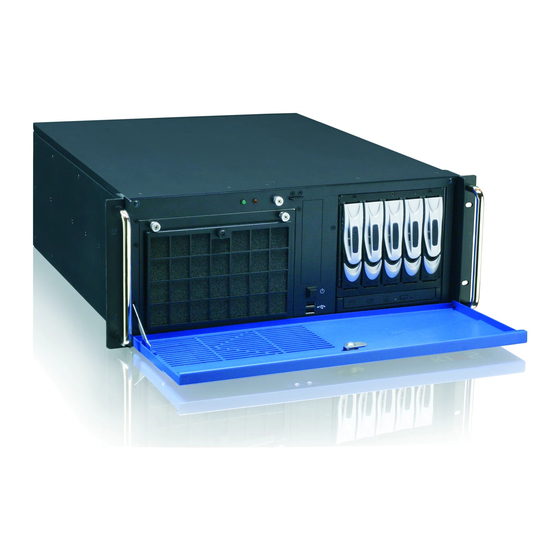
KISS 4U V2 – User's Guide (Version 1.01) 7.1. Front Side Depending on the ordered system configuration, the KISS 4U V2 platform will be delivered as rackmount or tower version. Fig. 10: Front side (rackmount version) with closed front access panel 1 19"... - Page 19 The power button, the power and HDD LEDs, 2x USB interfaces, 1x filter mat holder and the integrated drives are located at the front side of the KISS 4U V2 platform behind the access panel. Fig. 12: Front side (rackmount version) with opened access panel Legend for Fig.
-
Page 20: Interfaces On The Front Side
USB Interfaces 7.1.1.1. The KISS 4U V2 platform is equipped with two USB interfaces on the front side (see Fig. 12, pos. 4 and Fig. 14, pos. 2). You can connect various USB devices to these two USB 2.0 interface connectors. -
Page 21: Front Access Panel
KISS 4U V2 – User's Guide (Version 1.01) Power LED and HDD Activity LED 7.1.2.2. The indicators (see Fig. 12, pos. 15) of the KISS 4U V2 platform are located on the front side, behind the front access panel. 1 Power LED 2 HDD activity LED Fig. -
Page 22: Filter Mat And Filter Mat Holder
HDD installed) Externally accessible 3.5" drive bay (shown with covering plate) For KISS 4U V2 system configurations with a disk subsystem with five HDDs, the drive bays L1, L2 and L3 are occupied by this subsystem with removable HDDs. -
Page 23: Rear Side
KISS 4U V2 – User's Guide (Version 1.01) 7.2. Rear Side Depending on the KISS 4U V2 platform configuration ordered, the rear panel will have the external interfaces of the integrated motherboard or SBC board, any additional interfaces, the power supply unit and the air exhaust openings. -
Page 24: Interfaces On The Rear Side
7. Product Description KISS 4U V2 – User's Guide (Version 1.01) Fig. 17: Rear side of a KISS 4U V2 platform with Single Board Computer (SBC) and AC wide range PSU 1 “On/Off” switch of the AC PSU (depending on... -
Page 25: Power Supply
The power supply is located on the rear side of the KISS 4U V2 platform. On request, the KISS 4U V2 platform can optionally be equipped with an AC wide rage PSU, a redundant AC wide rage PSU or a DC PSU. The integrated power supply version also depends on the ordered system version and system configuration. -
Page 26: Grounding Stud
) does not disconnect the KISS 4U V2 platform from the main power source. Even you turn off the system using the power button ( Fig. 12, pos. 3) or the ON/OFF switch of this PSU, there is still a standby-voltage of 5 VSb on the motherboard or SBC. -
Page 27: Side View
Five M4 metric tapped holes are available at the left and right side of the unit (Fig. 25, pos. 2). These can be used in order to attach slide rails [not included; see chapter 11 “Slide Rails (Option)”] to the KISS 4U V2 platform for system installation into a 19”... -
Page 28: Assembly, Disassembly
(Fig. 26, pos.6) and the cover fastening screw (Fig. 12 and Fig. 13, pos. 14) at the front side of the KISS 4U V2 platform. When closing the cover, make sure that the fixing brackets ( Fig. -
Page 29: Fan Slide-In Module And Temperature Sensor
The fan slide-in module is mounted in a fan compartment on the front side of the system (Fig. 46, pos, 5). The system fans are temperature controlled via the temperature sensors installed in the KISS 4U V2 platform. Thus, a reliable air circulation for optimal active cooling of the platform is guaranteed. -
Page 30: Accessing Internal Components
8. Assembly, Disassembly KISS 4U V2 – User's Guide (Version 1.01) 8.4. Accessing Internal Components This chapter contains important information on working safely with internal components. Please follow these instructions when handling cards or replacing system fans. 8.4.1. Installing/Removing the Expansion Cards When you install (or remove) expansion cards please consider the corresponding safety instruction included in chapter 4 and the provided document “General Safety Instruction for IT Equipment”. - Page 31 8. Assembly, Disassembly KISS 4U V2 – User's Guide (Version 1.01) To install or remove an expansion card, perform the following steps: 1. Turn your system off and disconnect it from the AC power supply. In order to remove the cover, following knurled screws have to be loosen: the cover fastening screw (Fig.
- Page 32 8. Assembly, Disassembly KISS 4U V2 – User's Guide (Version 1.01) 3. Pull the cover out a little bit (Fig. 30) to release the cover centering and fixing brackets (Fig. 26, pos.3 and pos. 4) from the retaining brackets of the chassis (see Fig. 8, Fig. 9, pos. 4).
- Page 33 (see Fig. 8 and Fig. 9, pos. 7) has to be removed (step 1 to 4). Fig. 34: Opened KISS 4U V2 platform - removing the card hold down brackets 5. Loosen the internal and then the externally accessible fastening screw that secure the card hold down bracket for short expansion cards (see Fig.
- Page 34 12. Close the KISS 4U V2 platform and secure the cover with the captive knurled screws. The chassis of the KISS 4U V2 platform with attached cover is properly closed only, if the following knurled screws are tightened: the cover fastening screw (Fig.
-
Page 35: Installation In A 19" Industrial Cabinet
The openings for air intake and exhaust on the device must not be obstructed by objects. Leave at least 5 cm (1.969 ") of free space in front and behind the KISS 4U V2 platform to prevent the device from possibly overheating. -
Page 36: Starting Up
To connect the KISS 4U V2 platform to an AC power supply, perform the following steps: 1. The KISS 4U V2 systems with grounding studs marked with a PE symbol have to be grounded by establishing a large- area contact between the grounding stud (at the rear side) and an appropriate grounding connection point (see chapter 7.2.3 “Grounding Stud”, Fig. -
Page 37: Dc Power Connection
KISS 4U V2 – User's Guide (Version 1.01) 9.2. DC Power Connection The DC version of the KISS 4U V2 platform is equipped with a +24V or-48V power supply (with a 2-pin terminal block and an ON/OFF power switch). The system has to be mounted and installed only by qualified personnel for this area familiar with the associated dangers. -
Page 38: Operating System And Hardware Component Drivers
Downloads/Windows. If you have ordered KISS 4U V2 without a pre-installed operating system, you will need to install the operating system and the appropriate drivers for the system configuration you have ordered (optional hardware components) yourself. -
Page 39: Maintenance And Prevention
4 Fan slide-in module 5 Front access panel Fig. 37: Detail: Filter mat holder on the front side of the KISS 4U V2 platform To replace the filter mat, proceed as follows: 1. Open the front access panel (Fig. 37, pos. 5). - Page 40 8. Fix the filter mat holder by tightening the knurled screw (Fig. 39, pos. 5) to the bolt with tapped hole (Fig. 38, pos. 1) at the fan slide-in module. Defective components may only be replaced by Kontron original spare parts. Air filter mat: part number: 1035-6957.
-
Page 41: Cleaning Steel Mesh Guard (For Ip52 Protection Class Only)
KISS 4U V2 – User's Guide (Version 1.01) 10.1.1. Cleaning Steel Mesh Guard (for IP52 Protection Class only) If you have ordered a KISS 4U V2 platform with IP52 Protection Class, the filter mat holder (Fig. 42) is fitted with an additional steel mesh guard (Fig. 43). -
Page 42: Replacing The System Fans
KISS 4U V2 – User's Guide (Version 1.01) 10.2. Replacing the System Fans The operation of the KISS 4U V2 system is permitted only with a functional fan slide-in module! Defective components may only be replaced by Kontron original spare parts. - Page 43 10. Maintenance and Prevention KISS 4U V2 – User's Guide (Version 1.01) Fig. 47: Inner sider of the fan slide-in module Fig. 48: Fan slide-in module with inserted filter mat Legend for Fig. 45 and Fig. 46: 1 Fan slide-in module with two knurled screws...
-
Page 44: Replacing The Lithium Battery
5. Pay attention to the polarity of the battery. 6. The lithium battery must be replaced with an identical battery or a battery type recommended by Kontron Europe. 7. Reinstall the expansion cards which you removed and reconnect their data cables following the instructions in chapter 8.4.1 “Installing/Removing the Expansion Cards”... -
Page 45: Slide Rails (Option)
KISS 4U V2 – User's Guide (Version 1.01) 11. Slide Rails (Option) Kontron offers slide rails for installing the KISS 4U V2 platform into a 19" industrial cabinet. These can be ordered separately. The KISS 4U V2 systems should be installed into a 19" industrial cabinet with slide rails (PN: 1016-5807). -
Page 46: Technical Data
*The corresponding “KISS 4U V2 Systems - Configuration Guides” and the manual of the installed board can be downloaded from our web site at www.kontron.com by selecting the product name. 12.1. Electrical Specifications The corresponding electrical specifications of your KISS 4U V2 platform can be found on the type label. www.kontron.com... -
Page 47: Mechanical Specifications
12. Technical Data KISS 4U V2 – User's Guide (Version 1.01) 12.2. Mechanical Specifications Dimensions KISS 4U V2 Height 4U (177 mm) (6.968 ") Width Front: 19” (482 mm); Chassis: 430 mm (16.9") Depth Chassis: 472.5 mm (18.6") Weight (without Packaging) Approx. -
Page 48: Ce Directives And Standards
12. Technical Data KISS 4U V2 – User's Guide (Version 1.01) 12.4. CE Directives and Standards CE Directive Elektrical Safety General Product Safety Directive (GPSD) 2001/95/EC Low Voltage Directive (LVD) 2006/95/EC Electromagnetic EMC-Richtlinie 2004/108/EC Compatibility (EMC) CE Marking CE-Richtlinie 93/68/EEC... -
Page 49: Standard Interfaces - Pin Assignments
13. Standard Interfaces – Pin Assignments KISS 4U V2 – User's Guide (Version 1.01) 13. Standard Interfaces – Pin Assignments Low-active signals are indicated by a minus sign. 13.1.1. Serial Interface (RS232) Signal Name 9-pin D-SUB Connector (Data Carrier Detect) -
Page 50: Usb Port
13. Standard Interfaces – Pin Assignments KISS 4U V2 – User's Guide (Version 1.01) 13.1.3. USB Port Signal Name 4-pin USB Connector Type A Version 2.0 Data- Data+ 13.1.4. PS/2 Keyboard Connector Signal Name 6-pin Mini-DIN Connector Keyboard Data N.C. -
Page 51: Parallel Port (Lpt)
13. Standard Interfaces – Pin Assignments KISS 4U V2 – User's Guide (Version 1.01) 13.1.6. Parallel Port (LPT) Signal Name 25-pin D-SUB Connector (female) –STROBE DATA0 DATA1 DATA2 DATA3 DATA4 DATA5 DATA6 DATA7 –ACKN BUSY SELECT –AUTOFD –ERROR –INIT –SLCTIN 18–25 GND... -
Page 52: Technical Support
Be ready to explain the nature of your problem to the service technician. If you have questions about Kontron Europe or our products and services, you can reach us by the above-mentioned telephone number and on e-mail address or at: www.kontron.com...
Need help?
Do you have a question about the KISS 4U V2 and is the answer not in the manual?
Questions and answers