
Subscribe to Our Youtube Channel
Related Manuals for Nilfisk-ALTO FLOORTEC R 870


Summary of Contents for Nilfisk-ALTO FLOORTEC R 870
- Page 1 FLOORTEC R 870 Service Manual Floortec R 870 Battery - 9084404010 Floortec R 870 Petrol - 9084405010 Floortec R 870 LPG - 9084406010 English 2013-04 Form No. 1464826000...
-
Page 2: Table Of Contents
Symbols General Instructions Machine Lifting Machine Transportation Machine Nomenclature (know your machine) (Floortec R 870 Battery) Control Panel (Floortec R 870 Battery) Machine Nomenclature (know your machine) (Floortec R 870 Petrol/LPG) Control Panel (Floortec R 870 Petrol/LPG) Service and Diagnostic Equipment... - Page 3 Maintenance and Adjustments Fuse Check/Replacement (Floortec R 870 Battery) Troubleshooting Removal and Installation General Wiring Diagram (Floortec R 870 Battery) General Wiring Diagram (Floortec R 870 Petrol - LPG) Specifications Engine System - Petrol Functional Description Wiring Diagram Component Locations...
-
Page 4: Service Manual - Floortec R 870 Table Of Contents
Service Manual – Floortec R 870 Table of Contents Side Broom System Functional Description Wiring Diagram Component Locations Maintenance and Adjustments Troubleshooting Removal and Installation Specifications Wheel System, Non-Traction Component Locations Wheel System, Traction Functional Description Component Locations Troubleshooting Drive System Electronic Board Error Codes Table... -
Page 5: General Information
Service Manual Purpose and Field of Application The Service Manual is a technical resource intended to help service technicians when carrying out mainte- nance and repairs on the Floortec R 870, to guarantee the best cleaning performance and a long working life for the machine... -
Page 6: Conventions
General Information Service Manual – Floortec R 870 Conventions Forward, backward, front, rear, left or right are intended with reference to the operator’s position when driv- Service and Spare Parts Service and repairs must be performed only by authorised personnel or Nilfisk Service Centers. The authorised personnel is trained directly at the manufacturer’s premises and has original spare parts and accessories. -
Page 7: Safety
(For Floortec R 870 Battery/Petrol/LPG) – Before performing any maintenance, repair, cleaning or replacement procedure remove the igni- tion key, engage the parking brake and disconnect the battery (For Floortec R 870 Petrol/LPG - Disconnect the battery connector) – This machine must be used by properly trained operators only... - Page 8 General Information Service Manual – Floortec R 870 – Sharp turns must be made at slowest possible speed. Avoid: abrupt turns on incline, turns when the hopper is lifted – Do not lift the hopper when the machine is on incline The machine loses stability on incline or when the hopper is full –...
- Page 9 General Information Service Manual – Floortec R 870 (For Floortec R 870 Battery) – (For WET batteries only) Battery charging produces highly explosive hydrogen gas Keep the battery cover open during battery charging and perform this procedure in well-ventilated areas and away from naked flames.
- Page 10 General Information Service Manual – Floortec R 870 – The machine maximum capacity, operator’s weight not included, is 100 kg (the weight of waste). – In case of fire, use a powder fire extinguisher, not a water one. – Adjust the operation speed to suit the floor conditions.
-
Page 11: Machine Lifting
General Information Service Manual – Floortec R 870 – Do not use the machine if the battery charger cable or plug is damaged If the machine is not working as it should, has been damaged, left outdoors or dropped into water, return it to the Service Center –... -
Page 12: Machine Nomenclature (Know Your Machine) (Floortec R 870 Battery)
General Information Service Manual – Floortec R 870 Machine Nomenclature (know your machine) (Floortec R 870 Battery) Driver's seat with safety microswitch Flashing light Safety belts Battery compartment Can holder hood Seat position adjusting lever Hopper release and discharge lever... - Page 13 General Information Service Manual – Floortec R 870 Machine Nomenclature (Floortec R 870 Battery) (Continues) Serial number plate/technical data/conformity certification Electronic battery charger Hopper manual returning handle Drive pedal Rear hood with vacuum system Anchoring slots for transport (not for lifting)
- Page 14 General Information Service Manual – Floortec R 870 Machine Nomenclature (Floortec R 870 Battery) (Continues) Hopper hydraulic lifting system control unit Drive system electronic board Battery caps Fuseholder box (for WET batteries only) Vacuum system Lead batteries Battery motor connector...
-
Page 15: Control Panel (Floortec R 870 Battery)
General Information Service Manual – Floortec R 870 Control Panel (Floortec R 870 Battery) Vacuum system Switch for: Dust guard system warning light • Vacuum system activation (upper part) warning light (green) • Filter shaker activation (lower part) (green) Filter shaker switch... -
Page 16: Machine Nomenclature (Know Your Machine) (Floortec R 870 Petrol/Lpg)
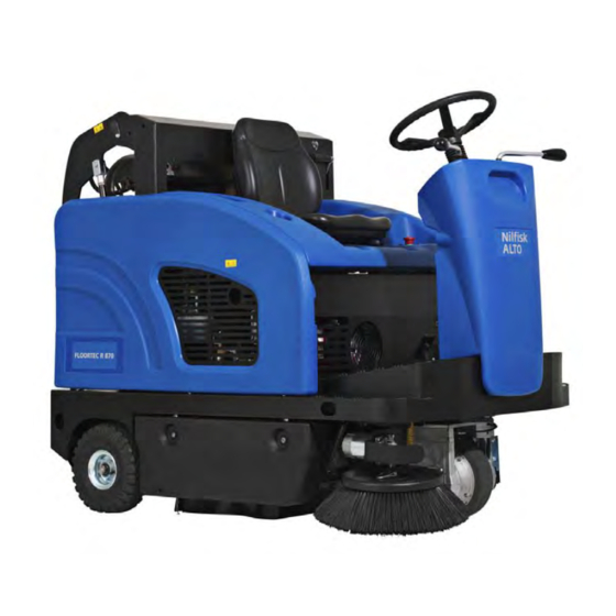
General Information Service Manual – Floortec R 870 Machine Nomenclature (know your machine) (Floortec R 870 Petrol/LPG) Driver's seat with safety microswitch Flashing light Safety belts Engine compartment Can holder hood Seat position adjusting lever Hopper release and discharge Steering wheel... - Page 17 General Information Service Manual – Floortec R 870 Machine Nomenclature (Floortec R 870 Petrol/LPG) (Continues) Serial number plate/technical data/ conformity certification Filler plug (SW4000 Petrol) Fuel tank (SW4000 Petrol) Hopper manual returning handle Drive pedal Rear hood with vacuum system...
- Page 18 General Information Service Manual – Floortec R 870 Machine Nomenclature (Floortec R 870 Petrol/LPG) (Continues) Hopper hydraulic lifting system control unit Drive system electronic board Fuseholder box Right side cover Dynamotor Vacuum system Batteries motor connector Engine Electrical component Open hood...
-
Page 19: Control Panel (Floortec R 870 Petrol/Lpg)
General Information Service Manual – Floortec R 870 Control Panel (Floortec R 870 Petrol/LPG) Switch for: Vacuum Dust guard • Vacuum system activation (upper part) system warning • Filter shaker activation (lower part) system warning light (green) Filter shaker/vacuum system switch... -
Page 20: Service And Diagnostic Equipment
General Information Service Manual – Floortec R 870 Service and Diagnostic Equipment Besides a complete set of standard meters, the following instruments are necessary to perform fast checks and repairs on Nilfisk-Advance machines: Laptop computer charged with the current version of EzParts, Adobe Reader and (if possible) Internet con- nection •... -
Page 21: Technical Data
General Information Service Manual – Floortec R 870 Technical Data Model Floortec R 870 Floortec R 870 Floortec R 870 Battery Petrol Cleaning width with one side broom 38.3 in (975 mm) with two side brooms 49.2 in (1,250 mm) Main broom size (length x diameter) 27.6 x 13.4 in (700 x 340 mm) - Page 22 General Information Service Manual – Floortec R 870 Technical Data (Continues) Floortec R 870 Floortec R 870 Floortec R 870 Model Battery Petrol Weight kerb weight without batteries 954 lb (433 Kg) kerb weight 1,126 lb (511 Kg) 1,135 lb (515 Kg)
- Page 23 General Information Service Manual – Floortec R 870 Technical Data (Continues) Caution! If the machine is to be used at ambient temperatures below +10°C, the oil should be changed with equivalent oil having a viscosity of 32 cSt. For temperatures below 0°C, use an oil with lower viscosity.
-
Page 24: Dimensions
General Information Service Manual – Floortec R 870 Dimensions 1640 mm (64.6 in) 1065 mm (42 in) P200092... -
Page 25: Maintenance
The following tables provides the scheduled maintenance The intervals shown may vary according to particu- lar working conditions, which are to be defined by the person in charge of the maintenance. For instructions on maintenance procedures, see the following paragraphs. Scheduled Maintenance Table (Floortec R 870 Battery) Every Every... -
Page 26: Scheduled Maintenance Table (Floortec R 870 Petrol/Lpg)
General Information Service Manual – Floortec R 870 Scheduled Maintenance Table (Floortec R 870 Petrol/LPG) Every Every Every Every Upon Every Procedure delivery year hours hours hours hours Engine oil level check Battery fluid level check Side and main broom height check... -
Page 27: Chassis System
Chassis System Service Manual – Floortec R 870 Chassis System Chassis (main parts) Front side supporting the steering assembly and side brooms Center side supporting batteries/engine with dynamotor and main broom Rear side supporting the hopper and rear wheels on hubs... -
Page 28: Control System
Service Manual – Floortec R 870 Control System Control System Functional Description The machine is started by the ignition key (SW1), located on the steering column. The key starts the machine when turned to II, thus powering the relay (K4). The relay (K4) stays on even when... -
Page 29: Dashboard Electronic Board Specifications
Service Manual – Floortec R 870 Control System Dashboard Electronic Board Specifications The dashboard electronic board performs the following: a HOUR COUNTER: By default, the 3-digit display (A) shows the number of hours stored in the hour counter. The hour counter proceeds with counting, only when the main broom turns. When the hour counter reaches 999, the next numbers are shown by the 3 more meaningful digits by adding a (low) dot for separating thousands (i.e.: 1234 will be shown as 1.23). - Page 30 Service Manual – Floortec R 870 Control System d BATTERY PROTECTION: Battery charge status is shown by the 3 LEDs depending on the type of battery (WET/GEL) according to the following diagram: Green LED on (fixed) V>22.0 V>22.2 Yellow LED on (fixed) 22.0>V>20.4...
-
Page 31: Wiring Diagram (Floortec R 870 Battery)
Service Manual – Floortec R 870 Control System Wiring Diagram (Floortec R 870 Battery) POSITIVE SIGNAL (FROM MACHINE ON “K4”) BATTERY NEGATIVE TERMINAL VACUUM SYSTEM FILTER SHAKER HOPPER LOWERING HOPPER LIFTING RELAY (K1) RELAY (K2) RELAY (K3B) RELAY (K3A) DISPLAY... - Page 32 Service Manual – Floortec R 870 Control System Wiring Diagram (Floortec R 870 Battery) POSITIVE SIGNAL (FROM MACHINE ON “K4”) BATTERY NEGATIVE TERMINAL EMERGENCY PUSH-BUTTON (SW0) LINE ELECTROMAGNETIC KEY CIRCUIT FUSE (F4) SWITCH (ES0) IGNITION KEY (SW1) MACHINE ON RELAY (K4)
-
Page 33: Wiring Diagram (Floortec R 870 Petrol/Lpg)
Service Manual – Floortec R 870 Control System Wiring Diagram (Floortec R 870 Petrol/LPG) POSITIVE SIGNAL (FROM MACHINE ON “K4”) BATTERY NEGATIVE TERMINAL DISPLAY ELECTRONIC BOARD FUSE (F3) HOPPER LOWERING HOPPER LIFTING FILTER SHAKER VACUUM SYSTEM RELAY (K3B) RELAY (K3A) - Page 34 Service Manual – Floortec R 870 Control System Wiring Diagram (Floortec R 870 Petrol/LPG) POSITIVE SIGNAL (FROM MACHINE ON “K4”) BATTERY NEGATIVE TERMINAL KEY CIRCUIT FUSE (F4) EMERGENCY PUSH-BUTTON (SW0) LINE ELECTROMAGNETIC SWITCH (ES0) IGNITION KEY (SW1) ENGINE SPARK PLUG (SPK)
-
Page 35: Component Locations
Service Manual – Floortec R 870 Control System Component Locations • Dashboard • Dashboard electronic board (EB2) • Ignition key (SW1) Dashboard electronic Dashboard board (EB2) Ignition key (SW1) P200096... -
Page 36: Troubleshooting
Service Manual – Floortec R 870 Control System Troubleshooting Trouble Possible Cause Remedy (For Floortec R 870 Battery) The battery connector is disconnected. Connect the battery connector. When turning the ignition key to “II”, the The fuse (F3) and/or (F0) is open. -
Page 37: Dashboard Electronic Board Alarm Codes
Service Manual – Floortec R 870 Control System Dashboard Electronic Board Alarm Codes The drive system warning light (A) on the dashboard electronic board (EB2) shows the error codes of the drive system electronic board (EB1). For the details, see the Wheel System, Drive chapter. - Page 38 Service Manual – Floortec R 870 Control System Connectors on the dashboard electronic board J1: MOLEX MINIFIT type, 18-ways vertical (A) P200221 Description Electronic V ref. I max. Connected to board in/out Electronic board power supply + Broom activation lever signal 24V (when the description is ON) <1A...
- Page 39 Service Manual – Floortec R 870 Control System J1: MOLEX MINIFIT type, 18-ways vertical (A) (continues) Further notes about dashboard electronic board (PIN - J1.14) The dashboard electronic board (EB2) recognises if it has been assembled on a Battery or Petrol/LPG machine version depending on the PIN J1.14 status:...
- Page 40 Service Manual – Floortec R 870 Control System J1: MOLEX MINIFIT type, 18-ways vertical (A) (continues) Petrol/LPG version (PIN - J1.14 not connected) The RPM value of the Petrol/LPG engine is fixed to 2.750 rpm ± 50 rpm The fixed RPM value of the Petrol/LPG engine should be in any case as follows •...
- Page 41 Service Manual – Floortec R 870 Control System J2: MOLEX MINIFIT type, 4-ways vertical (B) P200098 Description Electronic V ref. I max. Connected to board in/out Dashboard switch power supply (+) SW3, SW8 <1A Vacuum system activation signal 24V (when the description is ON) <1A...
-
Page 42: Removal And Installation
Disengage the four nuts (G) and remove the Open the battery/engine compartment hood dashboard electronic board (F) Disconnect the battery connector (Floortec R 870 Battery) - Disconnect the batteries (Floortec R Assembly 870 Petrol/LPG) 10 Assemble the components in the reverse order of... -
Page 43: Dust Control System
Service Manual – Floortec R 870 Dust Control System Dust Control System Functional Description The dust raised in the compartment of the main broom, is collected in the rear cargo area by a flow of air gener- ated by the dust control system... -
Page 44: Component Locations
Service Manual – Floortec R 870 Dust Control System Component Locations • Filter shaker/vacuum system switch (SW3) • Panel filter • Vacuum system motor (M1) • Vacuum system motor fuse (25 A - Battery) (30 A • Gasket Petrol/LPG) (F1) •... -
Page 45: Maintenance And Adjustments
Drive the machine on a level floor, engage the parking brake and turn the ignition key to “0”. Open the battery/engine compartment hood with the handle and fasten it with the support rod Disconnect the battery connector (Floortec R 870 Battery) - Disconnect the batteries (Floortec R 870 Petrol/LPG) - Page 46 (Only for Floortec R 870 Battery and Petrol) Fasten the filter shaker assembly (F) to the holder (G) (Only for LPG Floortec R 870). Remove the filter shaker assembly (F) 10 Lift the dust filter (H) and remove it from the...
-
Page 47: Troubleshooting
Service Manual – Floortec R 870 Dust Control System Troubleshooting Trouble Possible causes Remedy Dust/debris vacuuming is insufficient The filter is clogged Clean the dust filter by using the filter shaker or by disassembling it. The vacuum system compartment gasket is... -
Page 48: Removal And Installation
Drive the machine on a level floor, engage the parking brake and turn the ignition key to “0”. Open the battery/engine compartment hood with the handle and fasten it with the support rod Disconnect the battery connector (Floortec R 870 Battery) - Disconnect the batteries (Floortec R 870 Petrol/LPG) - Page 49 Service Manual – Floortec R 870 Dust Control System Filter Shaker Motor Disassembly/Assembly (Continues) Release the fastening clamp and disconnect the filter shaker connector (K). Loosen the knobs (D) and (E), then remove the filter shaker assembly (F), by sliding it forward,...
- Page 50 Service Manual – Floortec R 870 Dust Control System Electric Vacuum Fan Motor Amperage Check Warning! This procedure must be performed by qualified personnel only. Clean the dust filter. Open the battery/engine compartment hood with the handle and fasten it with the support rod Apply the amp clamps (A) on one cable (B) of the electric vacuum fan (C) Turn the ignition key to “I”...
- Page 51 Drive the machine on a level floor, engage the parking brake and turn the ignition key to “0”. Open the battery/engine compartment hood with the handle and fasten it with the support rod Disconnect the battery connector (Floortec R 870 Battery) - Disconnect the batteries (Floortec R 870 Petrol/LPG)
- Page 52 Service Manual – Floortec R 870 Dust Control System Electric Fan Disassembly/Assembly (Continues) At the workbench, disconnect the connector (D) from the electrical cable (E), by disengaging its pins. Unscrew the bulkhead cap (F) Remove the external screws (G) and remove the electric fan assembly (H) with its wiring harness (E) If necessary, remove the electric vacuum fan (I) from the assembly (H) as shown below.
-
Page 53: Specifications
Service Manual – Floortec R 870 Dust Control System Specifications Values Dust Control System Floortec R 870 Floortec R 870 Floortec R 870 Battery Petrol Vacuum system motor 0.35 hp (260 W) - 3,000 rpm Filter shaker motor 0.12 hp (90 W) - 6,000 rpm... -
Page 54: Dust Guard System
Service Manual – Floortec R 870 Dust Guard System Dust Guard System Functional Description The dust guard system sprays a thin film of water in front of each side broom, thus minimizing the dust raised by the broom itself The water used by the dust guard system is in a tank to be found inside the front column The water tank is connected to the machine hose system by means of a quick coupling equipped with an inte- grated valve, which allows to disconnect the tank without causing any water leaks. -
Page 55: Component Locations
Service Manual – Floortec R 870 Dust Guard System Component Locations • Dust guard system switch (SW8) • Water filter • Water tank • Spraying nozzle • Tank filler • Dust guard system fuse (5 A) (F5) • Water pump (M8) -
Page 56: Maintenance And Adjustments
Service Manual – Floortec R 870 Dust Guard System Maintenance and Adjustments Dust guard System Water Filter Cleaning Note: To prevent water from flowing out when cleaning the filter, turn on the dust guard system and empty the system tank. Drive the machine on a level floor. Turn the ignition key to “0” and engage the parking brake Operating in the area (A) of the machine, reach the water filter assembly (B) of the dust guard system. - Page 57 Service Manual – Floortec R 870 Dust Guard System Nozzle and Filter Cleaning Drive the machine on a level floor. Turn the ignition key to “0” and engage the parking brake On the front side of the side brooms, remove the ring nuts (A) (bayonet joint).
-
Page 58: Troubleshooting
Service Manual – Floortec R 870 Dust Guard System Troubleshooting Electrical components Electrical components Values Little water comes out from The filter and/or nozzle is clogged Clean/replace the spray nozzles The water filter is clogged Clean/replace The pump is not working... -
Page 59: Removal And Installation
On the right front upper side of the machine bed, remove the fastening screws (A) and (B) of the dust guard system water pump support plate (For Floortec R 870 Battery) If the screws (B) are hidden under the battery, the battery has to be removed (see the procedure in the Electrical System chapter) - Page 60 Service Manual – Floortec R 870 Dust Guard System Dust guard System Water Pump Disassembly/Assembly (Continues) On the right front upper side of the machine bed, disconnect the hose (C) of the water pump (D); disconnect the filter assembly input hose (E).
-
Page 61: Specifications
Service Manual – Floortec R 870 Dust Guard System Specifications Values Dust Guard System Floortec R 870 Floortec R 870 Floortec R 870 Battery Petrol Water tank capacity 5.3 US gal (20 liters) Pump 3A - 24V - 1.5 gpm US - 49 psi (3A - 24V - 5.7 l/min - 3.4 bar) -
Page 62: Electrical System
Service Manual – Floortec R 870 Electrical System Electrical System Functional Description (Floortec R 870 Battery) The electrical system is basically an electromechanical system at 24Vdc rated voltage in which the main part of the accessories are powered by relays controlled by switches The timing control of certain accessories and battery charging, as well as the display of the warning lights, takes place by dashboard electronic board (EB2). -
Page 63: Fuses
Service Manual – Floortec R 870 Electrical System Fuses All circuits and components are protected by fuses, located inside or outside the electrical component box. To protect motors from overloads when using the machine, there are manually resettable fuses (side brooms) or fuses interlocked to electronic protection systems (main broom, see Main Broom Motor Protection in Dash- board Electronic Board Specifications chapter). -
Page 64: Relay/Electromagnetic Switch/Diodes
Service Manual – Floortec R 870 Electrical System Relay/Electromagnetic Switch/Diodes Battery Versions Petrol and LPG Versions Pos. Nominal Nominal Protected Function Protected Function Size Size VACUUM SYSTEM RELAY VACUUM SYSTEM RELAY FILTER SHAKER RELAY FILTER SHAKER RELAY 30/40A HOPPER LIFTING... -
Page 65: Wiring Diagram (Floortec R 870 Battery)
Service Manual – Floortec R 870 Electrical System Wiring Diagram (Floortec R 870 Battery) WITHOUT ON BOARD BATTERY CHARGER KEY CIRCUIT FUSE (F4) IGNITION KEY MAIN FUSE (F0) EMERGENCY (SW1) PUSH-BUTTON (SW0) CONNECTOR + (C1) MACHINE ON RELAY (K4) 24V BATTERY (BAT) -
Page 66: Wiring Diagram (Floortec R 870 Petrol/Lpg)
Service Manual – Floortec R 870 Electrical System Wiring Diagram (Floortec R 870 Petrol/LPG) KEY CIRCUIT FUSE (F4) EMERGENCY CHARGE FUSE (FC) PUSH-BUTTON (SW0) ENGINE START ELECTROMAGNETIC IGNITION SWITCH (ES2) KEY (SW1) ENGINE SPARK PLUG (SPK) ENGINE ALERT FRAME (FR) -
Page 67: Component Locations (Floortec R 870 Battery)
Service Manual – Floortec R 870 Electrical System Component Locations (Floortec R 870 Battery) • Emergency push-button (SW0) • Wiring harnesses • Battery charger (CH) • Electrical component box • Flashing light (BE) • Battery connector (C1) • Batteries (BAT) -
Page 68: Component Locations (Floortec R 870 Petrol/Lpg)
• Electrical component box • Right side broom motor fuse (15 A) (FR1) • Batteries (BAT) • Left side broom motor fuse (15 A) (FR2) • Dynamotor (M5) • (Floortec R 870 P/LPG) Battery charge fuse (80 A) (FC) Emergency push-button (SW0) Flashing... - Page 69 Service Manual – Floortec R 870 Electrical System • Display electronic board fuse (3 A) (F3) Component Locations (Continues) • Filter shaker motor fuse (25 A - Battery) (30 A • Hopper lifting fuse (25 A - Battery) (30 A Petrol/...
-
Page 70: Maintenance And Adjustments
(*) When the red LED starts flashing, broom function is automatically deactivated. Battery Type Display (WET or GEL-AGM) (Floortec R 870 Battery) Each time the machine is turned on with the ignition key, the 3 battery charge LED indicators show the bat-... - Page 71 Service Manual – Floortec R 870 Electrical System Battery Removal/Installation and Battery Type Setting (WET or GEL/AGM) (Floortec R 870 Battery) Warning! Do not tilt the lead batteries (WET) to prevent the highly corrosive acid from leaking out of the batteries. Do not connect, not even accidentally, the battery positive and negative terminals by using tools, keys, etc.
- Page 72 Service Manual – Floortec R 870 Electrical System Battery Removal/Installation and Battery Type Setting (WET or GEL/AGM) (Floortec R 870 Battery) (Continues) Battery Setting (WET or GEL-AGM) Remove the support rod and close the battery compartment hood with the handle 10 Turn the ignition key to “I”...
- Page 73 Service Manual – Floortec R 870 Electrical System Battery Removal/Installation and Battery Type Setting (WET or GEL/AGM) (Floortec R 870 Battery) (Continues) Battery Removal Engage the parking brake Remove the ignition key Open the battery compartment hood (A) with the handle (B) and fasten it with the support rod (C)
- Page 74 Service Manual – Floortec R 870 Electrical System Battery Voltage Check (Floortec R 870 Petrol) Drive the machine on a level floor. Turn on the machine and engage the parking brake Open the engine compartment hood with the handle and fasten it with the support rod Check the voltage at the battery pins With the accessories turned off and the engine running, the voltage must be between 27 V and 31 V.
-
Page 75: Fuse Check/Replacement (Floortec R 870 Battery)
Service Manual – Floortec R 870 Electrical System Fuse Check/Replacement (Floortec R 870 Battery) Drive the machine on a level floor. 14 Check/replace the following fuses: • (J): FA main broom motor fuse (50 A). Turn the ignition key to “0” and engage the •... - Page 76 Service Manual – Floortec R 870 Electrical System Fuse Check/Replacement (Floortec R 870 Petrol/LPG) Drive the machine on a level floor. Check/replace the following fuses: • (J): FA main broom motor fuse (50 A). Turn the ignition key to “0” and engage the •...
-
Page 77: Troubleshooting
Service Manual – Floortec R 870 Electrical System Troubleshooting Trouble Possible causes Remedy The machine is not working The batteries are discharged or its connections are not Charge the batteries or clean/repair the efficient connections The batteries are broken Check the battery no-load voltage... -
Page 78: Removal And Installation
Service Manual – Floortec R 870 Electrical System Removal and Installation Battery Charger Disassembly/Assembly (Floortec R 870 Battery) Disassembly Drive the machine on a level floor. Turn the ignition key to “0” and engage the parking brake Open the battery compartment hood with the handle and fasten it with the support rod Disconnect the... - Page 79 Service Manual – Floortec R 870 Electrical System Dynamotor Carbon Brush Check/Replacement (Floortec R 870 Petrol) Disassembly Drive the machine on a level floor. Turn the ignition key to “0” and engage the parking brake Open the engine compartment hood with the handle and fasten it with the support rod Disconnect the batteries Remove the machine right side bulkhead, by lifting it to disengage it from the fasteners.
- Page 80 Service Manual – Floortec R 870 Electrical System Dynamotor Carbon Brush Check/Replacement (Floortec R 870 Petrol) (Con- tinues) Remove the fastening screws (G) of the electrical connections of the four carbon brushes (H) Remove the four carbon brushes (H) from their housings, by disengaging them from the retaining springs (I) 10 Check the four carbon brushes (H) for wear.
- Page 81 Service Manual – Floortec R 870 Electrical System Dynamotor Disassembly/Assembly (Floortec R 870 Petrol) Disassembly Remove the engine-dynamotor (see the procedure at the relevant paragraphs in Engine System, Petrol or Engine System, LPG). Remove the dynamotor carbon brushes (refer to the procedure “Dynamotor Carbon Brushes Check/ Replacement”)
- Page 82 Service Manual – Floortec R 870 Electrical System Dynamotor Disassembly/Assembly (Floortec R 870 Petrol) (Continues) Place a lever between the flange (I) of the dynamotor and the flange (J), then by means of the lever itself push the dynamotor in the direction of the arrow (K); in this condition, give a firm blow on the nut (A) in...
-
Page 83: General Wiring Diagram (Floortec R 870 Battery)
Service Manual – Floortec R 870 Electrical System General Wiring Diagram (Floortec R 870 Battery) POSITIVE SIGNAL (FROM MACHINE ON “K4”) BATTERY NEGATIVE TERMINAL MAIN BROOM SIDE BROOM ELECTROMAGNETIC RELAY (K5) SWITCH (ES1) MAIN BROOM FUSE (FA) P200127A... - Page 84 Service Manual – Floortec R 870 Electrical System General Wiring Diagram (Floortec R 870 Battery) POSITIVE SIGNAL (FROM MACHINE ON “K4”) BATTERY NEGATIVE TERMINAL HOPPER TEMPERATURE SENSOR (S4) DISPLAY ELECTRONIC BOARD FUSE (F3) SIDE BROOM HOPPER LIFTING SENSOR (S1) RELAY (K5)
- Page 85 Service Manual – Floortec R 870 Electrical System General Wiring Diagram (Floortec R 870 Battery) WITHOUT ON BOARD BATTERY CHARGER POSITIVE SIGNAL (FROM MACHINE ON “K4”) BATTERY NEGATIVE TERMINAL REVERSE GEAR BUZZER (BZ1) EMERGENCY KEY CIRCUIT LINE ELECTROMAGNETIC PUSH-BUTTON (SW0)
-
Page 86: General Wiring Diagram (Floortec R 870 Petrol - Lpg)
Service Manual – Floortec R 870 Electrical System General Wiring Diagram (Floortec R 870 Petrol - LPG) POSITIVE SIGNAL (FROM MACHINE ON “K4”) BATTERY NEGATIVE TERMINAL CHARGE FUSE (FC) ENGINE START ELECTROMAGNETIC SWITCH (ES2) SIDE BROOM RELAY (K5) MAIN BROOM FUSE (FA) - Page 87 Service Manual – Floortec R 870 Electrical System General Wiring Diagram (Floortec R 870 Petrol - LPG) POSITIVE SIGNAL (FROM MACHINE ON “K4”) BATTERY NEGATIVE TERMINAL HOPPER TEMPERATURE SENSOR (S4) DISPLAY ELECTRONIC BOARD FUSE (F3) HOPPER LIFTING SIDE BROOM SENSOR (S1)
- Page 88 Service Manual – Floortec R 870 Electrical System General Wiring Diagram (Floortec R 870 Petrol - LPG) POSITIVE SIGNAL (FROM MACHINE ON “K4”) BATTERY NEGATIVE TERMINAL REVERSE GEAR BUZZER (BZ1) KEY CIRCUIT FUSE (F4) EMERGENCY PUSH-BUTTON (SW0) DIODE (D2) LINE ELECTROMAGNETIC...
-
Page 89: Specifications
Service Manual – Floortec R 870 Electrical System Specifications Values Electrical components Floortec R 870 Floortec R 870 Floortec R 870 Battery Petrol Total absorbed power 2.7 hp (2.0 kW) Values Batteries Floortec R 870 Battery Battery pack 1 12 x 2V x 360A 6 EPzS 360 (WET) -
Page 90: Engine System - Petrol
Service Manual – Floortec R 870 Engine System - Petrol Engine System - Petrol Functional Description The engine system generates electric current for all The fuel tank is fastened outside the engine, in the machine functions rear side of the machine The tank has a fuel level in- The assembly consists of an internal combustion en- dicator with float, and a valve with integrated filter. -
Page 91: Component Locations
Service Manual – Floortec R 870 Engine System - Petrol Component Locations • Petrol engine • Reserve sensor (S5) • Filler neck • Diode (S1) • Fuel tank • Oil Alert Sensor • Fuel opening/closing valve Petrol engine Filler neck... -
Page 92: Maintenance And Adjustments
Service Manual – Floortec R 870 Engine System - Petrol Maintenance and Adjustments Engine RPM Check To check the engine speed, use the indicator (A) fastened to the engine pulley, with a rev counter light (B) which can be seen from the front outer side of the engine compartment Alternatively use a rev counter (C) to be applied to the spark plug wire (D) For the engine rpm, see Specifications paragraph. - Page 93 Service Manual – Floortec R 870 Engine System - Petrol Engine Air Filter Cleaning Check 11 Assemble the foam filter (D) on the paper filter Caution! Running the engine without air (E), then assemble the filter element. Ensure filters, or with damaged filters, that the gasket (H) is properly placed under the can cause a faster engine filter element.
- Page 94 Service Manual – Floortec R 870 Engine System - Petrol Engine Oil Level Check Caution! Running the engine with a low oil level can damage the engine itself. Note: The oil alert system will automatically stop the engine before the oil level goes down under the safety limit. To avoid a sudden engine stop, always check the oil level before each start-up. Drive the machine on a level ground and engage the parking brake Turn the ignition key to “0”...
- Page 95 Service Manual – Floortec R 870 Engine System - Petrol Engine Oil Change Caution! The discharged engine oil must be disposed of properly according to the Law in force. Note: It is advisable to change the oil when the engine is still hot, to make the oil downflow easier. Drive the machine on a level ground and engage the parking brake Turn the ignition key to “0”...
- Page 96 Service Manual – Floortec R 870 Engine System - Petrol Engine Filter Trap Cleaning Warning! The petrol is highly flammable and explosive, it can burn or cause serious injuries. Turn off the engine, and keep it far from sparks, flames and other sources of heat. Handle the fuel outdoors only. Wipe immediately any fuel accidentally spilled out. Drive the machine on a level ground and engage the parking brake Turn the ignition key to “0”...
- Page 97 Service Manual – Floortec R 870 Engine System - Petrol Engine Spark Plug Check/Replacement For the type of spark plug to be used, see Technical 12 When the original spark plug is reinstalled, Data chapter tighten 1/8 - 1/4 turn once the spark plug is in...
- Page 98 Service Manual – Floortec R 870 Engine System - Petrol Engine Baffle Plate Cleaning Warning! If the engine was running, the silencer will be very hot. Let it cool down before operating on the baffle plate. Drive the machine on a level ground and engage the parking brake Turn the ignition key to “0”...
-
Page 99: Troubleshooting
Service Manual – Floortec R 870 Engine System - Petrol Troubleshooting Trouble Possible causes Remedy The engine does not start The fuel valve lever is closed Open the fuel lever The air control is in standard position. Turn the lever to cold start position. -
Page 100: Removal And Installation
Service Manual – Floortec R 870 Engine System - Petrol Removal and Installation Engine-Dynamotor Unit Disassembly/Assembly Disassembly Drive the machine on a level floor. Turn the ignition key to “0” and engage the parking brake Open the engine compartment hood with the handle and fasten it with the support rod Disconnect the batteries Remove the machine right side bulkhead (A), by lifting it to disengage it from the fasteners. - Page 101 Service Manual – Floortec R 870 Engine System - Petrol Engine-Dynamotor Unit Disassembly/Assembly (Continues) Disconnect the wiring harnesses (F) of the dynamotor (G) from the electrical cable (H) and the batteries (I) (mark each position for proper reassembly) Disconnect the engine start electrical connector (J)
- Page 102 Service Manual – Floortec R 870 Engine System - Petrol Engine Unit Disassembly/Assembly Disassembly Remove the engine-dynamotor unit (see the procedure in the previous paragraph) Remove the dynamotor unit (see the procedure in Electrical System paragraph) Remove the screws (A) and separate the engine assembly (B) from the holder (C). Engine weight: 24 kg approx If necessary, unscrew the three screws (D) and remove the air deflector (E) from the engine.
-
Page 103: Specifications
Service Manual – Floortec R 870 Engine System - Petrol Specifications Engine Values Make Honda GX-200 Model Regulated power (ISO 1585) 6.7 kW Working speed 2,750 ± 50 rpm Oil type SAE 5 W 30 - SYNTHETIC API SJ Average consumption 0.45 gph US (1.7 liters/hour) -
Page 104: Engine System - Lpg
Service Manual – Floortec R 870 Engine System - LPG Engine System - LPG Functional Description The engine system generates electric current for all The IMPCO T60-A-NN-2 two-phase pressure reducer machine functions lowers the gas pressure, which then reaches the car-... -
Page 105: Component Locations
Service Manual – Floortec R 870 Engine System - LPG Component Locations • LPG tank fastening band • Hose • LPG tank • Pipe • LPG tank fitting • Safety valve • LPG tank opening/closing valve • Diode (D3) LPG tank... - Page 106 Service Manual – Floortec R 870 Engine System - LPG Component Locations (Continues) • LPG wiring harness • Hose • Engine • Solenoid valve with filter (EV1) • Hose • Pressure valve (reserve) (S4) • LPG pressure regulator LPG wiring harness...
-
Page 107: Maintenance And Adjustments
Service Manual – Floortec R 870 Engine System - LPG Maintenance and Adjustments Engine RPM Check To check the engine speed, use the indicator (A) fastened to the engine pulley, with a rev counter light (B) which can be seen from the front outer side of the engine compartment Alternatively use a rev counter (C) to be applied to the spark plug wire (D) For the engine rpm, see Specifications paragraph. - Page 108 Service Manual – Floortec R 870 Engine System - LPG Engine Air Filter Cleaning Check 11 Assemble the foam filter (D) on the paper filter Warning! Running the engine without air (E), then assemble the filter element. Ensure filters, or with damaged filters, that the gasket (H) is properly placed under the can cause a faster engine filter element.
- Page 109 Service Manual – Floortec R 870 Engine System - LPG Engine Oil Level Check Caution! Running the engine with a low oil level can damage the engine itself. Note: The oil alert system will automatically stop the engine before the oil level goes down under the safety limit. To avoid a sudden engine stop, always check the oil level before each start-up. Drive the machine on a level ground and engage the parking brake Turn the ignition key to “0”...
- Page 110 Service Manual – Floortec R 870 Engine System - LPG Engine Oil Change Caution! The discharged engine oil has to be disposed of properly according to the Law in force. Note: It is advisable to change the oil when the engine is still hot, to make the oil downflow easier. Drive the machine on a level ground and engage the parking brake Turn the ignition key to “0”...
- Page 111 Service Manual – Floortec R 870 Engine System - LPG Engine Spark Plug Check/Replacement For the type of spark plug to be used, see Technical 13 Perform steps 4 and 3 in the reverse order Data chapter Warning! A wrong spark plug can damage the engine.
- Page 112 Service Manual – Floortec R 870 Engine System - LPG Engine Baffle Plate Cleaning Warning! If the engine was running, the silencer will be very hot. Let it cool down before operating on the baffle plate. Drive the machine on a level ground and engage the parking brake Turn the ignition key to “0”...
- Page 113 Service Manual – Floortec R 870 Engine System - LPG LPG System Leakage Check Warning! This procedure has to be performed by personnel qualified to handle the LPG systems, according to the law in force. Moreover, it is necessary to wear accident-prevention clothes, according to the...
- Page 114 Service Manual – Floortec R 870 Engine System - LPG LPG System Leakage Check (Continues) Apply evenly the spry product that detects gas leaks “SUPER BALL, OFF. PROD. C.C.I.A.A. 186231 (VI)” (or equivalent) on all the fittings of the LPG system, starting from the LPG tank fitting (A) to the fitting (F) between the hose and carburettor (G).
- Page 115 Service Manual – Floortec R 870 Engine System - LPG Solenoid Valve Filter Cleaning Warning! This procedure has to be performed by personnel qualified to handle the LPG systems, according to the law in force. Moreover, it is necessary to wear accident-prevention clothes, according to the law in force (heavy gloves, antistatic non-synthetic clothes, suitable to cover the whole body, antistatic and antispark shoes, helmets with visor;...
- Page 116 Service Manual – Floortec R 870 Engine System - LPG Solenoid Valve Filter Cleaning (Continues) 10 Remove the fastening screws (G) of the pressure regulator assembly with valves (H) 11 Remove the pressure regulator assembly with valves (H) 12 At the workbench, remove the “T” fitting (I) from the fitting (L).
- Page 117 Service Manual – Floortec R 870 Engine System - LPG Solenoid Valve Filter Cleaning (Continues) 14 Overturn the solenoid valve (N) and fasten its body on a vice (P) with soft jaws 15 Unscrew the solenoid valve fitting (M). 16 Remove the filter holder (Q).
- Page 118 Service Manual – Floortec R 870 Engine System - LPG Solenoid Valve Filter Cleaning (Continues) 17 Remove the filter (T). The filter holder gasket (U) has to be replaced with the corresponding spare part, before reassembly. 18 Remove and discard the gaskets (U) and (S), then clean the filter (T), the flange (V) of the solenoid valve body, the filter holder (Q) and the fitting (M) with compressed air (maximum pressure 6 Bar).
- Page 119 Service Manual – Floortec R 870 Engine System - LPG Adjustment Warning! This procedure has to be performed by personnel qualified to handle the LPG systems, according to the law in force. Check the CO emissions With the proper tool, check the engine CO emissions, according to the law in force in the country where...
-
Page 120: Troubleshooting
Service Manual – Floortec R 870 Engine System - LPG Troubleshooting Trouble Possible causes Remedy The engine does not start The fuel does not reach the carburettor. Check that the tank valve is open (LPG) The air control is in standard position. -
Page 121: Removal And Installation
Service Manual – Floortec R 870 Engine System - LPG Removal and Installation LPG System Emptying Warning! This procedure has to be performed by personnel qualified to handle the LPG systems, according to the law in force. Moreover, it is necessary to wear accident- prevention clothes, according to the law in force (heavy gloves, antistatic non- synthetic clothes, suitable to cover the whole body, antistatic and antispark shoes, helmets with visor;... - Page 122 Service Manual – Floortec R 870 Engine System - LPG LPG System Hose and Fitting Disassembly/Assembly Warning! This procedure has to be performed by personnel qualified to handle the LPG systems, according to the law in force. Moreover, it is necessary to wear accident-prevention clothes, according to the law in force (heavy gloves, antistatic non-synthetic clothes, suitable to cover the whole body, antistatic and antispark shoes, helmets with visor;...
- Page 123 Service Manual – Floortec R 870 Engine System - LPG LPG System Hose and Fitting Disassembly/Assembly (Continues) • The fittings (D) are equipped with inner gaskets. • The fittings (E) are provided with sealant. Caution! If the fittings (E) are turned very slightly, their tightness can be compromised (because the sealant “brakes”), thus those fittings has to be unscrewed and screwed again after having applied new sealant, as shown below.
- Page 124 Service Manual – Floortec R 870 Engine System - LPG Pressure Regulator Removal/Installation Warning! This procedure has to be performed by personnel qualified to handle the LPG systems, according to the law in force. Moreover, it is necessary to wear accident-prevention clothes, according to the law in force (heavy gloves, antistatic non-synthetic clothes, suitable to cover the whole body, antistatic and antispark shoes, helmets with visor;...
- Page 125 Service Manual – Floortec R 870 Engine System - LPG Pressure Regulator Removal/Installation (Continues) Disconnect the electrical connections (D) and (F) 10 Remove the fastening screws (G) of the pressure regulator assembly with valves (H) 11 Remove the pressure regulator assembly with valves (H) 12 At the workbench, remove the fitting (I) from the fitting (J).
- Page 126 Service Manual – Floortec R 870 Engine System - LPG Pressure Valve Removal/Installation Warning! This procedure has to be performed by personnel qualified to handle the LPG systems, according to the law in force. Moreover, it is necessary to wear accident-prevention clothes, according to the law in force (heavy gloves, antistatic non-synthetic clothes, suitable to cover the whole body, antistatic and antispark shoes, helmets with visor;...
- Page 127 Service Manual – Floortec R 870 Engine System - LPG Solenoid Valve Removal/Installation Warning! This procedure has to be performed by personnel qualified to handle the LPG systems, according to the law in force. Moreover, it is necessary to wear accident-prevention clothes, according to the law in force (heavy gloves, antistatic non-synthetic clothes, suitable to cover the whole body, antistatic and antispark shoes, helmets with visor;...
- Page 128 Service Manual – Floortec R 870 Engine System - LPG Solenoid Valve Removal/Installation (Continues) Disconnect the electrical connections (D) and (F) 10 Remove the fastening screws (G) of the pressure regulator assembly with valves (H) 11 Remove the pressure regulator assembly with valves (H) 12 At the workbench, remove the “T”...
- Page 129 Service Manual – Floortec R 870 Engine System - LPG Engine-Dynamotor Unit Disassembly/Assembly Disassembly Empty the LPG system (see the procedure in “LPG System Emptying”) Drive the machine on a level floor. Turn the ignition key to “0” and engage the parking brake...
- Page 130 Service Manual – Floortec R 870 Engine System - LPG Engine-Dynamotor Unit Disassembly/Assembly (Continues) Disconnect the wiring harnesses (F) of the dynamotor (G) from the electrical cable (H) and the batteries (I) (mark each position for proper reassembly) Disconnect the engine start electrical connector (J)
- Page 131 Service Manual – Floortec R 870 Engine System - LPG Engine Unit Disassembly/Assembly Disassembly Remove the engine-dynamotor unit (see the procedure in the previous paragraph) Remove the dynamotor unit (see the procedure in Electrical System paragraph) Remove the screws (A) and separate the engine assembly (B) from the holder (C). Engine weight: 24 kg approx If necessary, unscrew the three screws (D) and remove the air deflector (E) from the engine.
-
Page 132: Specifications
Service Manual – Floortec R 870 Engine System - LPG Specifications Values Engine System - LPG Floortec R 870 LPG Make Honda GX-200 Model Regulated power (ISO 1585) 6.7 kW Working speed 2,750 ± 50 rpm Oil type SAE 5 W 30 - SYNTHETIC API SJ Reserve 17.4 psi (1.2 Bar) -
Page 133: Hopper System
Service Manual – Floortec R 870 Hopper System Hopper System Functional Description The hopper lifting system is operated by an hydraulic cylinder driven by an electric pump motor (M3) with integrated hydraulic unit The pump motor (M3) is powered by 2 relays (K3A) and (K3B), driven respectively for hopper lifting and lower-... -
Page 134: Wiring Diagram
Service Manual – Floortec R 870 Hopper System Wiring Diagram HOPPER HOPPER LIFTING DISPLAY ELECTRONIC LOWERING RELAY (K3A) BOARD FUSE (F3) RELAY (K3B) J1.1 - Electronic board power supply + HOPPER HOPPER PUMP LIFTING/LOWERING FUSE (F6) SWITCH (SW5) J2.4 - Control panel switch power supply (-) -
Page 135: Hydraulic Diagram
Service Manual – Floortec R 870 Hopper System Hydraulic diagram HYDRAULIC CILINDER VALVE LOCK DOWN HIGH PRESSURE PRESSURE RELIEF VALVE RELIEF VALVE HYDRAULIC POWER UNIT P200152... -
Page 136: Component Locations
Service Manual – Floortec R 870 Hopper System Component Locations • Hopper lifting system warning light • Closed hopper sensor (S1) • Hopper movement enabling switch (SW4) • Hopper linkages • Hopper lifting/lowering switch (SW5) • Hopper Hopper lifting system warning... - Page 137 Service Manual – Floortec R 870 Hopper System Component Locations (Continues) • Check valve • Hydraulic hoses • Hydraulic cylinder • Hydraulic control unit • Hydraulic oil tank • Hopper lifting fuse (25 A - Battery) (30 A Petrol/LPG) (F6)
-
Page 138: Maintenance And Adjustments
The hydraulic system oil should be disposed of properly according to the Law in force. (Only for Floortec R 870 Battery, with battery box). Install the right body side (A) and engage it with the fasteners Remove the support rod and close the battery/engine hood... -
Page 139: Troubleshooting
Service Manual – Floortec R 870 Hopper System Troubleshooting Trouble Possible causes Remedy The hopper does not lift. The fuse (F6) is open. Replace the fuse. The hopper does not dump. The hopper is too low. Lift the hopper at a minimum height of 350 mm. -
Page 140: Removal And Installation
Turn the ignition key to “0” and engage the parking brake Open the battery/engine compartment hood with the handle and fasten it with the support rod Disconnect the battery connector (Floortec R 870 Battery) - Disconnect the batteries (Floortec R 870 Petrol/LPG) - Page 141 Service Manual – Floortec R 870 Hopper System Hopper Disassembly/Assembly Disassembly Empty the hopper Drive the machine on a level floor. Engage the parking brake Operating on the machine controls, as shown in the User Manual, lift the hopper (A), then lower it by laying it on a wide holder (B), as shown in the figure (to safely support it during the disassembly).
- Page 142 Service Manual – Floortec R 870 Hopper System Hopper Disassembly/Assembly (Continues) Assembly 11 Assemble the components in the reverse order of disassembly 12 Check that the hopper operates properly and that it is properly aligned; if necessary align it as shown...
- Page 143 Service Manual – Floortec R 870 Hopper System Hopper and Lifting Arm Disassembly/Assembly Disassembly Empty the hopper and then close it Drive the machine on a level floor. Engage the parking brake Ensure that the hopper is closed On the upper area of the right hopper arm (A), remove the cotter pin and the pin (B).
- Page 144 Service Manual – Floortec R 870 Hopper System Hopper and Lifting Arm Disassembly/Assembly (Continues) Apply a proper safety lifting rope (H) on the upper part of the hopper arms, as shown in the figure. (Hopper weight with lifting arms: 16 kg)
- Page 145 Turn the ignition key to “0” and engage the parking brake Open the battery/engine compartment hood with the handle and fasten it with the support rod Disconnect the battery connector (Floortec R 870 Battery) - Disconnect the batteries (Floortec R 870 Petrol/LPG) Remove the machine right side bulkhead (A), by lifting it to disengage it from the fasteners.
- Page 146 Service Manual – Floortec R 870 Hopper System Hydraulic Control Unit Disassembly/Assembly (Continues) Disconnect the electrical connector (E) of the hydraulic unit (F) Remove the hollow screws (G) and disconnect the hydraulic hoses (H) from the hydraulic unit (F) Retrieve the gaskets (I) If necessary, collect the hydraulic system oil in a proper container.
- Page 147 Service Manual – Floortec R 870 Hopper System Hydraulic Control Unit Disassembly/Assembly (Continues) 10 Remove the front screw (J) and the rear screw (K) fastening the hydraulic unit (F) 11 Remove the hydraulic control unit (F) Assembly 12 Assemble the components in the reverse order of disassembly, and note the following: •...
- Page 148 Service Manual – Floortec R 870 Hopper System Hydraulic Hose Disassembly/Assembly Disassembly Drive the machine on a level floor. Ensure that the hopper is closed Turn the ignition key to “0” and engage the parking brake Open the battery/engine compartment hood with the handle and fasten it with the support rod Remove the machine right side bulkhead, by lifting it to disengage it from the fasteners.
- Page 149 Service Manual – Floortec R 870 Hopper System Hydraulic Hose Disassembly/Assembly (Continues) Collect the hydraulic system oil in a proper container Plug the disconnected fittings, to prevent debris from entering into the hydraulic system. Warning! Hydraulic system oil is highly corrosive.
- Page 150 Service Manual – Floortec R 870 Hopper System Hydraulic Cylinder Disassembly/Assembly Disassembly Warning! The hydraulic system oil should be disposed of Drive the machine on a level floor. properly according to the Law Ensure that the hopper is closed in force.
-
Page 151: Specifications
Service Manual – Floortec R 870 Hopper System Specifications Values Hopper System Floortec R 870 Floortec R 870 Floortec R 870 Battery Petrol 19.8 US gal (75 liters) Hopper capacity Maximum weight liftable by the hopper 220 lb (100 kg) Hopper maximum lifting height 62.6 in (1,590 mm) -
Page 152: Optional And Accessories
Service Manual – Floortec R 870 Optional and Accessories Optional and Accessories Description Illustration DUSTGUARD™ SYSTEM KIT (See Dust Guard System chapter) SAFETY BELT KIT ROOF COVER KIT... - Page 153 Service Manual – Floortec R 870 Optional and Accessories Description Illustration PROTECTION ROOF KIT WORKING LIGHT KIT The working light kit improves visibility in dark environments. The headlights are installed under the chassis, in the front side of the sweeper.
-
Page 154: Steering System
Service Manual – Floortec R 870 Steering System Steering System Functional Description The steering wheel is fastened to the steering column and connected to a shaft with a cardan joint The movement is transmitted with pinion and chain to the ring gear, which determines the steering. The ring... -
Page 155: Component Locations
Service Manual – Floortec R 870 Steering System Component Locations • Steering wheel • Steering shaft • Steering column • Steering assembly • Cardan joint • Steering chain Steering Steering column wheel Steering shaft Cardan joint Steering assembly Steering chain... -
Page 156: Removal And Installation
Service Manual – Floortec R 870 Steering System Removal and Installation Steering Wheel Disassembly/Assembly Disassembly Drive the machine on a level floor. Turn the ignition key to “0” and engage the parking brake Disengage and remove the cover (A) Unscrew the nut (B) and remove the washer (C) With a suitable puller, remove the steering wheel (D) using the surface (E) of the steering shaft and the threaded holes (F) of the steering wheel, or its lower edge (G);... - Page 157 Service Manual – Floortec R 870 Steering System Steering Chain Disassembly/Assembly Disassembly If possible, place the machine on a hoisting system. Turn the ignition key to “0” and engage the parking brake Steer the front wheel until the junction link (A) of the steering chain (B) becomes visible...
- Page 158 Service Manual – Floortec R 870 Steering System Steering Assembly Removal/Installation Refer to the procedure: Driving Wheel and Steering Unit Disassembly/Assembly...
-
Page 159: Main Broom System
Service Manual – Floortec R 870 Main Broom System Main Broom System Functional Description By using the left lever on the dashboard the main broom support system lowers, because it is released by a metal cable; the broom is kept pressed to the ground by two gas springs that ensure the contact with the... -
Page 160: Component Locations
Service Manual – Floortec R 870 Main Broom System Component Locations • Main broom lifting/lowering lever • Main broom motor fuse (50A) (FA) • Main broom overload warning light • Front skirt lifting pedal • Main broom height adjusting knob •... - Page 161 Service Manual – Floortec R 870 Main Broom System Component Locations (Continues) • Rear skirt • Motor pulley • Front skirt • Right side skirt • Left side skirt • Broom pulley • Lowered main broom enabling sensor (S2) • Device to adjust the parallelism between the •...
-
Page 162: Maintenance And Adjustments
Service Manual – Floortec R 870 Main Broom System Maintenance and Adjustments Main Broom Height Check And Adjustment Note: Brooms with harder or softer Note: The knob can be used both to bristles are available. This adjust the print and to adjust procedure is applicable to all the broom according to the types of brooms. bristle wear. Check the main broom distance from the ground,... - Page 163 Service Manual – Floortec R 870 Main Broom System Main Broom Height Check and Adjustment (Continues) Turn the fasteners and remove the left door Loosen the locknuts (C) Turn the screws (D) to adjust the height of the broom left side, and adjust it to the right side, as follows: •...
- Page 164 Service Manual – Floortec R 870 Main Broom System Main Broom Disassembly/Assembly Note: Brooms with harder or softer bristles are available. This procedure is applicable to all types of brooms. Warning! It is advisable to wear protective gloves when replacing the main broom because there can be sharp debris between the bristles. Disassembly Drive the machine on a level ground and engage the parking brake Turn the ignition key to “0”...
- Page 165 Service Manual – Floortec R 870 Main Broom System Main Broom Disassembly/Assembly (Continues) Assembly Check that the drive hub (F) is free from dirt or foreign materials (cords, rags, etc.) accidentally rolled The main broom (E) must be installed with the bristles rows (G) bent as shown in the figure.
-
Page 166: Skirt Height Check And Adjustment
Service Manual – Floortec R 870 Main Broom System Skirt Height Check and Adjustment Preliminary Operations Empty the hopper (as shown in the User Manual), because the weight of the waste inside the hopper can affect the skirt height check Drive the machine on a level ground that is suitable for checking the skirt height Turn the ignition key to “0”... - Page 167 Service Manual – Floortec R 870 Main Broom System Skirt Height Check and Adjustment (Continues) Front and Rear Skirt Check Remove the main broom Check the front skirt (F) and rear skirts (G) and (H) for integrity Replace the skirts when they have cuts (C) larger than 20 mm or cracks/tears (D) larger than 10 mm (see the procedure in “Skirt Disassembly/Assembly”)
-
Page 168: Troubleshooting
Service Manual – Floortec R 870 Main Broom System Troubleshooting Trouble Possible causes Remedy The main broom does not The safety system has activated. Turn off the machine and then turn it on again. work and the warning light Check the condition of the main broom (debris (76) flashes. -
Page 169: Removal And Installation
Service Manual – Floortec R 870 Main Broom System Removal and Installation Driving Belt Visual Inspection and Replacement Check Drive the machine on a level floor. Turn the ignition key to “0” and engage the parking brake Remove the machine right door by turning the relevant fasteners Visually inspect the entire length of the belt (A) to make sure it is intact and shows no signs of cuts, tears or cracks, if necessary replace it. - Page 170 Service Manual – Floortec R 870 Main Broom System Skirt Disassembly/Assembly Preliminary Operations Empty the hopper (as shown in the User Manual), because the weight of the waste inside the hopper can affect the skirt height check Drive the machine on a level ground that is suitable for checking the skirt height Turn the ignition key to “0”...
- Page 171 Service Manual – Floortec R 870 Main Broom System Skirt Disassembly/Assembly (Continues) Front Skirt Removal and Installation Note: It is advisable to place the machine on a hoisting system. 10 Remove the main broom 11 Remove the side brooms 12 On the left front side of the front skirt (D), disengage the clip (E) then disconnect the terminal (F) of the...
- Page 172 Service Manual – Floortec R 870 Main Broom System Skirt Disassembly/Assembly (Continues) Rear Skirt Removal and Installation 19 Remove the main broom 20 Lift the hopper to the end-of-stroke Warning! Place a safety rod under the lifted hopper. 21 In the hopper compartment, remove the nuts (P) and then remove the strap (Q) and the skirt (R).
- Page 173 Service Manual – Floortec R 870 Main Broom System Main Broom Motor Amperage Check Warning! This procedure must be performed by qualified personnel only. Remove the main broom Check that the main broom drive hub is free from dirt or foreign materials (ropes, rags, etc.) accidentally rolled up, which can prevent it from rotating.
- Page 174 Service Manual – Floortec R 870 Main Broom System Main Broom Motor Amperage Check (Continues) If the amperage is higher, perform the following procedures to detect and correct it: • Check the relevant fuse (FA) for proper tightening • Check if there is dust or dirt (cords, cables, etc.) on the broom drive hub.
- Page 175 Service Manual – Floortec R 870 Main Broom System Main Broom Motor Disassembly/Assembly Disassembly Remove the main broom driving belt (see the procedure in “Driving Belt Visual Inspection and Replacement”) Disconnect the connector (A) of the main broom motor (B)
- Page 176 Service Manual – Floortec R 870 Main Broom System Main Broom Motor Carbon Brush Check/Replacement Disassembly Remove the main broom motor (see the procedure in the previous paragraph) At the workbench, remove the nuts (A) and the guard (B) of the main broom motor (C).
- Page 177 Service Manual – Floortec R 870 Main Broom System Main Broom Motor Pulley Disassembly/Assembly Disassembly Remove the main broom motor belt (see the procedure in “Driving Belt Visual Inspection and Replacement”) While keeping the pulley (C) locked, remove the screw (A) and retrieve the washer (B).
- Page 178 Service Manual – Floortec R 870 Main Broom System Main Broom Drive Hub and Bearing Disassembly/Assembly BEARINGS Disassembly Remove the main broom Lift the hopper to the end-of-stroke Warning! Place a safety rod under the lifted hopper. Remove the main broom driving belt (see the procedure in “Driving Belt Visual Inspection and Replacement”)
- Page 179 Service Manual – Floortec R 870 Main Broom System Main Broom Drive Hub and Bearing Disassembly/Assembly (Continues) DRIVE HUB Disassembly Remove the main broom Lift the hopper to the end-of-stroke Warning! Place a safety rod under the lifted hopper. In the hopper compartment, remove the nut (L) while keeping the drive hub locked (M).
- Page 180 Service Manual – Floortec R 870 Main Broom System Main Broom Gas Spring Disassembly/Assembly Disassembly Place the machine on a hoisting system Remove the main broom With the knob (A), lower the main broom until the end of stroke. Use the lever (B) to lower the main broom...
- Page 181 Service Manual – Floortec R 870 Main Broom System Main Broom Gas Spring Disassembly/Assembly (Continues) In front of the main broom, loosen the nut (F) of the gas springs (G). Insert and tighten the screw with a 8 mm nut (H) in the hole (I)
- Page 182 Service Manual – Floortec R 870 Main Broom System Main Broom Lifting Cable Disassembly/Assembly Disassembly If possible, place the machine on a hoisting system. Remove the main broom Remove the left side broom, if equipped. Remove the fastening screws (A) of the fairing (B) from the steering column...
- Page 183 Service Manual – Floortec R 870 Main Broom System Main Broom Lifting Cable Disassembly/Assembly (Continues) 11 Unscrew the nut (I) and remove the pin (J) 12 Remove the screw (K) 13 Remove the locknut (L) and disconnect the tie rod (M) from the housing with cut (N)
- Page 184 Service Manual – Floortec R 870 Main Broom System Main Broom Lifting Cable Disassembly/Assembly (Continues) Assembly and Adjustment 19 Assemble the components in the reverse order of disassembly, and note the following: • Adjust the cable (S) as shown below: 20 Place the locknut (T) near the relevant nut, without tightening it.
- Page 185 Service Manual – Floortec R 870 Main Broom System Lowered Main Broom Enabling Sensor Disassembly/Assembly and Adjust- ment Disassembly If possible, place the machine on a hoisting system. Remove the left side broom, if equipped. On the machine left lower front side, unscrew the locknut (A) and remove the enabling sensor (B) from its housing Disengage the sensor electrical cable (C) from its fasteners, then disconnect the relevant connector.
- Page 186 Service Manual – Floortec R 870 Main Broom System Specifications Values Main Broom System Floortec R 870 Floortec R 870 Floortec R 870 Battery Petrol Main broom size (length x diameter) 27.6 x 13.4 in (700 x 340 mm) Main broom motor 0.8 hp (600 W) - 550 rpm...
-
Page 187: Side Broom System
Service Manual – Floortec R 870 Side Broom System Side Broom System Functional Description By using the right lever on the dashboard the side brooms lower, because they are released by a metal cable. In case of side impact, the system can return by means of a spring which absorbs the shock. -
Page 188: Component Locations
Service Manual – Floortec R 870 Side Broom System Component Locations • Side broom lifting/lowering lever • Broom height adjusting ring nuts • Side broom motor (M6) (M7) • Side broom • Lowered right side broom enabling sensor (S3) • Left side broom motor fuse (15 A) (FR1) •... -
Page 189: Maintenance And Adjustments
Service Manual – Floortec R 870 Side Broom System Maintenance and Adjustments Side Broom Height Check and Adjustment Turn the fasteners and remove the left or right Note: Brooms with harder or softer door bristles are available. This procedure is applicable to all For the right side broom, operate on the idle types of brooms. -
Page 190: Troubleshooting
Service Manual – Floortec R 870 Side Broom System Troubleshooting Trouble Possible causes Remedy The right/left side broom does The broom has not been properly adjusted in height/ Adjust not clean properly parallelism The broom is excessively worn Replace The side brooms do not work... -
Page 191: Removal And Installation
Service Manual – Floortec R 870 Side Broom System Removal and Installation Side Broom Disassembly/Assembly Note: Brooms with harder or softer bristles are available. This procedure is applicable to all types of brooms. Warning! It is advisable to wear protective gloves when replacing the main broom because there can be sharp debris between the bristles. -
Page 192: Side Broom Motor Amperage Check
Service Manual – Floortec R 870 Side Broom System Side Broom Motor Amperage Check Warning! This procedure must be performed by qualified personnel only. Remove the side broom of the relevant motor Place wedges (A) on the rear wheels of the machine With a proper hoisting system applied to the machine chassis, to the front wheel area (B), lift the machine a few centimetres, in order to let the front wheel turn freely without touching the floor. - Page 193 Service Manual – Floortec R 870 Side Broom System Side Broom Motor Amperage Check (Continues) If the amperage is higher, perform the following procedures to detect and correct it: • Check if there is dust or dirt (cords, cables, etc.) on the side broom hub.
- Page 194 Service Manual – Floortec R 870 Side Broom System Side Broom Motor Disassembly/Assembly Disassembly Remove the side broom of the motor to be detached Lower the side broom with the lever Disconnect the connector (A) of the broom motor (B)
- Page 195 Service Manual – Floortec R 870 Side Broom System Side Broom Motor Carbon Brush Check/Replacement Disassembly Remove the side broom motor (see the procedure in the previous paragraph) Take the motor (A) to the workbench and, if necessary, mark the position (B) of the cap (C) as to the...
- Page 196 Service Manual – Floortec R 870 Side Broom System Side Broom Lifting Cable Disassembly/Assembly Disassembly If possible, place the machine on a hoisting system. Remove the relevant side broom Above the side broom motor, remove the screw with nut (A) and release the grommet (B) of the cable (C)
- Page 197 Service Manual – Floortec R 870 Side Broom System Side Broom Lifting Cable Disassembly/Assembly (Continues) On the other cable terminal (C), remove the screw with nut (G) and release the relevant grommet (F) of the cable (C) to be removed...
- Page 198 Service Manual – Floortec R 870 Side Broom System Lowered Right Side Broom Enabling Sensor Disassembly/Assembly and Adjustment Disassembly If possible, place the machine on a hoisting system. Remove the right side broom On the right front lower side of the machine, unscrew the locknut (A) and remove the enabling sensor (B) from its housing Disengage the sensor electrical cable (C) from its fasteners, then disconnect the relevant connector.
-
Page 199: Specifications
Service Manual – Floortec R 870 Side Broom System Specifications Values Side Broom System Floortec R 870 Floortec R 870 Floortec R 870 Battery Petrol Working width (with one side broom) 38.3 in (975 mm) Working width (with two side brooms) 49.2 in (1,250 mm) -
Page 200: Wheel System, Non-Traction
(Only for Floortec R 870 Petrol/LPG). In case of super elastic wheels, the notch on the wheel support flange must be placed near the letter “S”; in case of polyurethane wheels the notch must be placed near the letter “P”... - Page 201 Service Manual – Floortec R 870 Wheel System, Non-Traction Specifications Values Wheel System, Non Traction Floortec R 870 Floortec R 870 Floortec R 870 Battery Petrol Rear axle kerb weight 860 lb (390 Kg) 672 lb (305 Kg) 670 lb (304 Kg) Rear wheel specific pressure on the floor 102 psi (0.7 N/mm...
-
Page 202: Wheel System, Traction
Service Manual – Floortec R 870 Wheel System, Traction Wheel System, Traction Functional Description The main components for the drive system are: the driving wheel assembly with integrated disc brake, the drive pedal, the electronic board, forward/reverse gear switch and the brake pedal with parking brake lever. - Page 203 Service Manual – Floortec R 870 Wheel System, Traction If the electronic board detects a fault in the drive system, this will appear as a code on the display and the malfunction warning light (A) on the electronic board (EB2) will turn on...
-
Page 204: Component Locations
Service Manual – Floortec R 870 Wheel System, Traction Component Locations • Forward/reverse gear switch (SW2) • Drive system malfunction warning light • Driver’s seat safety microswitch (SW7) • Service brake pedal • Parking brake lever • Drive pedal (R1) - Page 205 Service Manual – Floortec R 870 Wheel System, Traction Component Locations (Continues) • Driving wheel (M0) • Disc brake • Drive system electronic board (EB1) • Main fuse (150 A) (F0) • Reverse gear buzzer (BZ1) Driving wheel (M0) Disc brake...
-
Page 206: Troubleshooting
Service Manual – Floortec R 870 Wheel System, Traction Troubleshooting Trouble Possible causes Remedy The machine does not move The batteries are discharged or its connections are not Charge the batteries or clean/repair the efficient connections The drive pedal control assembly (R1) is broken... -
Page 207: Drive System Electronic Board Error Codes Table
Service Manual – Floortec R 870 Wheel System, Traction Drive System Electronic Board Error Codes Table No. of MEANING FIRST PROCEDURE IF THE PROBLEM PERSISTS flashes of the warning light (A) Not active Potentiometer wiring harness Check the pedal wiring harness R1... -
Page 208: Drive System Electronic Board Parameter Table
Service Manual – Floortec R 870 Wheel System, Traction Drive System Electronic Board Parameter Table The drive system electronic board software contains some parameters which can be modified by the user with the ITALSEA programmer (P/N 9097297000) PARAMETER DEFAULT NOTE... - Page 209 Service Manual – Floortec R 870 Wheel System, Traction PARAMETER DEFAULT NOTE Parameter connected to the hardware configuration PIN 11-J1 HARDWARE N.C. SWITCH CONFIGURATION (DO NOT MODIFY!) Parameter connected to the hardware configuration A1 ALARM ENABLING DISABLE (DO NOT MODIFY!)
- Page 210 Service Manual – Floortec R 870 Wheel System, Traction Connectors on Drive System Electronic Board Power Connections - Battery Power Connections (male screw terminals M 6) Ref. Description Electronic board V ref. I max. Connected to in/out Electronic board power supply +...
- Page 211 Service Manual – Floortec R 870 Wheel System, Traction J2: MOLEX MINIFIT type, 16-ways vertical Description Electronic V ref. I max. Connected to board in/out Potentiometer positive power supply <1A Potentiometer input 0 - 5V (0V when the pedal is released <1A...
-
Page 212: Removal And Installation
Service Manual – Floortec R 870 Wheel System, Traction Removal and Installation Brake Caliper, Pad, Brake Disc Disassembly/Assembly Disassembly Drive the machine on a level floor. Turn the ignition key to “0” Ensure that the machine cannot move by placing opposite wedges on the rear wheels Steer the front wheel to the right, about 90°. - Page 213 Service Manual – Floortec R 870 Wheel System, Traction Brake Caliper, Pad, Brake Disc Disassembly/Assembly (Continues) 10 If necessary, separate the outer pad (M) from the bracket (N), as shown below: • Disengage the retaining ring (O) and remove the spring (P) •...
- Page 214 Service Manual – Floortec R 870 Wheel System, Traction Brake Caliper, Pad, Brake Disc Disassembly/Assembly (Continues) Assembly 11 Assemble the components in the reverse order of disassembly, and note the following: • Adjust the position of the nuts (F) until the bracket (G) comes into contact with the brake disc (I) and with the inner pad (L);...
- Page 215 Service Manual – Floortec R 870 Wheel System, Traction Brake Cable Disassembly/Assembly Disassembly If possible, place the machine on a hoisting system. Turn the ignition key to “0” Ensure that the machine cannot move by placing opposite wedges (A) on the rear wheels Remove the left side broom, if equipped.
-
Page 216: Brake Cable Adjustment
Service Manual – Floortec R 870 Wheel System, Traction Brake Cable Disassembly/Assembly (Continues) Assembly 10 Assemble the components in the reverse order of disassembly, and note the following: • Adjust the brake according to the following procedure Brake Cable Adjustment Ensure that the machine cannot move by placing opposite wedges on the rear wheels Steer the front wheel to the right, about 90°, so that the brake system becomes accessible. - Page 217 Service Manual – Floortec R 870 Wheel System, Traction Driving Wheel Amperage Check Warning! This procedure must be performed by qualified personnel only. Place wedges (A) on the rear wheels of the machine With a proper hoisting system applied to the machine chassis, to the front wheel area (B), lift the machine a few centimetres, in order to let the front wheel turn freely without touching the floor.
- Page 218 Service Manual – Floortec R 870 Wheel System, Traction Driving Wheel Amperage Check (Continues) If the amperage is higher, perform the following procedures to detect and correct it: • Check that there is no dust or debris (ropes, cables, etc.) on the driving wheel, that can prevent it from turning •...
- Page 219 Turn the ignition key to “0” and engage the parking brake Open the battery/engine compartment hood Disconnect the battery connector (Floortec R 870 Battery) - Disconnect the batteries (Floortec R 870 Petrol/LPG) Remove in sequence each of the four carbon brushes of the drive system motor, as shown below: •...
- Page 220 Service Manual – Floortec R 870 Wheel System, Traction Drive System Motor Carbon Brush Check/Replacement (Continues) Check the four carbon brushes (D) for wear. The carbon brushes are worn when: • The contact with the motor armature is insufficient • The contact surface is not integral •...
- Page 221 Service Manual – Floortec R 870 Wheel System, Traction Front Wheel Rubber Ring Disassembly/Assembly Disassembly If possible, place the machine on a hoisting system. Turn the ignition key to “0” Ensure that the machine cannot move by placing opposite wedges (A) on the...
- Page 222 Service Manual – Floortec R 870 Wheel System, Traction Front Wheel Rubber Ring Disassembly/Assembly (Continues) Remove the screws (G) on the left side of the front wheel assembly Remove the spacer (H) Remove the left bracket (I); if necessary use a puller (J)
- Page 223 Open the battery/engine compartment hood Disconnect the battery connector (Floortec R 870 Battery) - Disconnect the batteries (Floortec R 870 Petrol/LPG) With a proper hoisting system applied to the machine chassis, to the front wheel area (B), lift the machine a few centimetres, in order to easily remove the driving wheel assembly.
- Page 224 Service Manual – Floortec R 870 Wheel System, Traction Driving Wheel and Steering Unit Disassembly/Assembly (Continues) Steer the front wheel to the right, about 90°. 10 Unscrew nut and locknut (G) then remove the brake cable (H) from the brackets (I) Retrieve the spring...
- Page 225 Service Manual – Floortec R 870 Wheel System, Traction Driving Wheel and Steering Unit Disassembly/Assembly (Continues) 14 At the base of the steering column (R) remove the screws (S) and remove the cover (T) 15 Remove the four fastening screws (U) of the driving wheel assembly (V) 16 Remove from the machine the driving wheel assembly (V) with the steering assembly (W), by removing the hub (X) from the steering shaft;...
- Page 226 Service Manual – Floortec R 870 Wheel System, Traction Front Driving Wheel Armature Disassembly/Assembly Disassembly Remove the driving wheel and steering assembly (see the procedure in the previous paragraph) Workbench, remove the screws (A) on the left side of the front wheel assembly.
- Page 227 Service Manual – Floortec R 870 Wheel System, Traction Front Driving Wheel Armature Disassembly/Assembly (Continues) Remove the fastening screws (H) of the carbon brush cap (J) Retrieve the washers (I) Remove the carbon brush cap assembly (J); take the greatest care in order not to remove/displace the...
- Page 228 Service Manual – Floortec R 870 Wheel System, Traction Front Driving Wheel Armature Disassembly/Assembly (Continues) Assembly 11 Assemble the components in the reverse order of disassembly, and note the following: • Remove any dust or debris from the stator and removed components •...
- Page 229 Service Manual – Floortec R 870 Wheel System, Traction Accelerator Pedal Disassembly/Assembly Disassembly If possible, place the machine on a hoisting system. Loosen the screw (B) under the accelerator pedal (A) Remove the accelerator pedal (A) from the shaft (C)
- Page 230 Turn the ignition key to “0” and engage the parking brake Open the battery/engine compartment hood Disconnect the battery connector (Floortec R 870 Battery) - Disconnect the batteries (Floortec R 870 Petrol/LPG) On the left rear side of the battery/engine compartment, disengage the protection caps (A) and...
- Page 231 Turn the ignition key to “0” and engage the parking brake Open the battery/engine compartment hood Disconnect the battery connector (Floortec R 870 Battery) - Disconnect the batteries (Floortec R 870 Petrol/LPG) On the lower side of the battery/engine compartment (A), remove the driver’s seat microswitch connector...
-
Page 232: Specifications
Service Manual – Floortec R 870 Wheel System, Traction Specifications Values Wheel System Traction Floortec R 870 Floortec R 870 Floortec R 870 Battery Petrol U-turn space (right - left) 75.6 - 74.4 in (1,920 - 1,890 mm) Forward speed 4.3 mi/h (7 km/h)
Need help?
Do you have a question about the FLOORTEC R 870 and is the answer not in the manual?
Questions and answers