Table of Contents
Advertisement
Available languages
Available languages
Quick Links
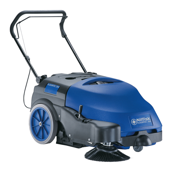
FLOORTEC 350
All Parts available from
www.sparesgiant.com
01772 329 565
DEUTSCH
FRANÇAIS
ENGLISH
NEDERLANDS
BETRIEBSANLEITUNG
ORIGINALANLEITUNG
MANUEL D'UTILISATION
INSTRUCTIONS D'ORIGINE
USER MANUAL
ORIGINAL INSTRUCTION
GEBRUIKSAANWIJZING
ORIGINELE INSTRUCTIES
146 3083 000 (2) 2008-11
www.nilfisk-alto.com
Advertisement
Chapters
Table of Contents

Subscribe to Our Youtube Channel
Related Manuals for Nilfisk-ALTO FLOORTEC 350


Summary of Contents for Nilfisk-ALTO FLOORTEC 350
- Page 1 FLOORTEC 350 All Parts available from www.sparesgiant.com 01772 329 565 BETRIEBSANLEITUNG DEUTSCH ORIGINALANLEITUNG MANUEL D’UTILISATION FRANÇAIS INSTRUCTIONS D’ORIGINE USER MANUAL ENGLISH ORIGINAL INSTRUCTION GEBRUIKSAANWIJZING NEDERLANDS ORIGINELE INSTRUCTIES 146 3083 000 (2) 2008-11...
- Page 2 Тип / Typ / Typ / Type / Tipo / Tüüp / Type / Tyyppi / Type / Τύπος / FLOORTEC 350 Típus / Tipo / Tipas / Tips / Type / Type / Tipo / Typ / Tip / Тип / Typ / Typ / Tip / Tip : Сериен...
-
Page 3: Table Of Contents
HAUPTKEHRWALZENHÖHE ÜBERPRÜFEN UND EINSTELLEN ....................13 HAUPTKEHRWALZE AUSBAUEN/EINBAUEN ..........................14 STAUBFILTER REINIGEN UND ÜBERPRÜFEN, ABFALLBEHÄLTERDICHTUNGEN ÜBERPRÜFEN ........15 HÖHE UND FUNKTIONSFÄHIGKEIT DER SCHMUTZFANGKLAPPEN ÜBERPRÜFEN ............16 BATTERIE LADEN..................................16 FEHLERSUCHE ................................17 VERSCHROTTUNG ............................... 18 146 3083 000(2)2008-11 A FLOORTEC 350... -
Page 4: Einleitung
Das Gerätebaujahr ist in der Konformitätserklärung enthalten und entspricht ferner den ersten beiden Ziffern der Seriennummer des Geräts. Diese Informationen sind für die Bestellung von Ersatzteilen erforderlich. Bitte notieren Sie hier die Gerätedaten. 01772 329 565 GERÄTEMODELL ................GERÄTESERIENNUMMER .............. 146 3083 000(2)2008-11 A FLOORTEC 350... -
Page 5: Andere Referenzanleitungen
Augenschein nehmen kann. Für die Schadenersatzleistung unverzüglich mit der Transportfi rma in Verbindung setzen. Überprüfen, ob der Lieferumfang des Geräts nachstehender Liste entspricht: – Technische Unterlagen: • Betriebsanleitung der Kehrmaschine www.sparesgiant.com • Ersatzteilliste der Kehrmaschine • 1 Sicherung des Ansauganlagenmotors 01772 329 565 146 3083 000(2)2008-11 A FLOORTEC 350... -
Page 6: Sicherheit
Nicht ohne geeignete stabile Sicherheitsstützen unter dem angehobenen Gerät arbeiten. – Gerät nicht in Räumen einsetzen, in denen sich schädliche, gefährliche, brennbare und/oder explosive Pulver, Flüssigkeiten oder Dämpfe befi nden: Dieses Gerät ist nicht zum Aufnehmen gefährlicher Stäube geeignet. 146 3083 000(2)2008-11 A FLOORTEC 350... - Page 7 Müssen Bauteile ausgewechselt werden, stets beim Kundendienst oder einem autorisierten Vertragshändler ORIGINALERSATZTEILE anfordern. – Das Gerät enthält giftige und schädliche Stoffe (Batterien, Kunststoffe etc.), für die eine Entsorgung durch entsprechende Stellen (siehe Kapitel „Verschrottung“) gesetzlich vorgeschrieben ist. Fahrzeug am Ende seiner Lebensdauer vorschriftsmäßig entsorgen! 146 3083 000(2)2008-11 A FLOORTEC 350...
-
Page 8: Gerätebeschreibung
Hauptkehrwalze Drehregler Höheneinstellung Hauptkehrwalze Hinterräder, angetrieben Staufächer Ladegerätkabel Ladegerätkabelfach Rückschaltbare Sicherung Seitenbesenmotor Rückschaltbare Sicherung Hauptmotor Batterie All Parts available from Staubfi lter Seitenbesenmotor Hauptmotor www.sparesgiant.com Antriebsrad Ansauglüfter Ladegerät 01772 329 565 20 19 S311348 146 3083 000(2)2008-11 A FLOORTEC 350... -
Page 9: Zubehör/Sonderausstattung
GEL, 12 V, 80 Ah Ladegerät Hauptmotor 200 W, 1.500 U/min Seitenbesenmotor 40 W Ansauganlagenmotor 50 W Staubansaugung und -fi lterung Werte Staubfi lter 5-10 μm (Polyester) Oberfl äche Staubfi lter Unterdruck Hauptkehrwalzenraum 12 mm H 146 3083 000(2)2008-11 A FLOORTEC 350... -
Page 10: Schaltplan
Batterien Schwarz Ladegerät Hellblau LED-Platine Braun Relais Grün Hauptsicherung Grau Sicherung Ansauglüfter Orange Sicherung Seitenbesen Rosa Hauptmotor Ansauganlagenmotor Violett Seitenbesenmotor Weiß Hauptschalter Gelb Mikroschalter Abfallbehälter All Parts available from www.sparesgiant.com 01772 329 565 S311349 146 3083 000(2)2008-11 A FLOORTEC 350... -
Page 11: Betrieb
Schubbügel (6) festhalten, Fahrhebel (5) langsam drücken und mit Kehren beginnen. Gerät abstellen Zum Anhalten des Geräts Fahrhebel (5) loslassen. Hauptschalter (1) auf 0 stellen und Ansauganlage, Seitenbesen und Hauptkehrwalze anhalten. Hebel (12) nach hinten ziehen, in die Halterung einrasten und Seitenbesen (11) anheben. 146 3083 000(2)2008-11 A FLOORTEC 350... -
Page 12: Gerät Im Kehrbetrieb
Gerät leicht anheben, sodass Schmutzfangklappen, Hauptkehrwalze und Räder den Boden nicht berühren. ERSTE BETRIEBSZEIT Nach den ersten 8 Betriebsstunden die Spannung der Befestigungs- und Verbindungselemente des Geräts überprüfen. Alle sichtbaren Teile auf Unversehrtheit und Dichtigkeit prüfen. 146 3083 000(2)2008-11 A FLOORTEC 350... -
Page 13: Wartung
Sorgfältig prüfen, ob das Ladegerätkabel (18) und der entsprechende Stecker Abriebspuren, Schnitte, Risse oder sonstigen Schäden aufweisen. Sind das Kabel des Ladegeräts und den entsprechenden Stecker beschädigt, wenden Sie sich bitte an einen Nilfi sk Alto- Kundendienst. 146 3083 000(2)2008-11 A FLOORTEC 350... -
Page 14: Seitenbesenhöhe Überprüfen Und Einstellen
Seitenbesen (B) von den drei Stiften (C) lösen und abnehmen. Den neuen Seitenbesen in die drei Stifte (C) einrasten und am Gerät montieren. Knopf (A) eindrehen. Höhe des neuen Seitenbesens wie im vorstehenden Abschnitt erläutert einstellen. S311351 Abbildung 2 146 3083 000(2)2008-11 A FLOORTEC 350... -
Page 15: Hauptkehrwalzenhöhe Überprüfen Und Einstellen
Bauteile kommen, wodurch die Betriebsdauer stark verkürzt wird. www.sparesgiant.com Die vorstehend angeführte Überprüfung besonders sorgfältig vornehmen und das Gerät niemals unter anderen als den angegebenen Bedingungen verwenden. 01772 329 565 S311353 Abbildung 4 146 3083 000(2)2008-11 A FLOORTEC 350... -
Page 16: Hauptkehrwalze Ausbauen/Einbauen
Die neue Hauptkehrwalze durch Ausführen der Schritte 3 bis 6 in umgekehrter Reihenfolge einbauen. Höhe der neuen Hauptkehrwalze wie im vorstehenden Abschnitt erläutert einstellen. All Parts available from www.sparesgiant.com 01772 329 565 S311355 Abbildung 6 S311356 Abbildung 7 146 3083 000(2)2008-11 A FLOORTEC 350... -
Page 17: Staubfilter Reinigen Und Überprüfen, Abfallbehälterdichtungen Überprüfen
Die ausgebauten Bauteile in der umgekehrten Reihenfolge des Ausbaus wieder einbauen. HINWEIS Beim Filtereinbau muss die Dichtung (E, Abb. 10) in S311358 die auf der Abbildung gezeigte Richtung weisen. Abbildung 9 S311359 Abbildung 10 146 3083 000(2)2008-11 A FLOORTEC 350... -
Page 18: Höhe Und Funktionsfähigkeit Der Schmutzfangklappen Überprüfen
Leuchtet die grüne Kontrollleuchte (F) auf, ist die Batterien geladen. Ladegerätkabel (B) vom Stromnetz trennen und in das entsprechende Fach (C) legen. HINWEIS Ist das Ladegerät ans Stromnetz angeschlossen, werden alle Gerätefunktionen automatisch gesperrt. S311361 Abbildung 12 146 3083 000(2)2008-11 A FLOORTEC 350... -
Page 19: Fehlersuche
Stecker in die Netzsteckdose gesteckt wird Für weitere Informationen setzen Sie sich bitte mit einem Nilfi sk Alto-Kundendienst in Verbindung, bei dem die Service-Anleitung erhältlich ist. All Parts available from www.sparesgiant.com 01772 329 565 146 3083 000(2)2008-11 A FLOORTEC 350... -
Page 20: Verschrottung
Kunststoffl eitungen und -teile – Elektrische und elektronische Teile (*) Wenden Sie sich insbesondere für die Verschrottung der elektrischen und elektronischen Teile an die örtliche Nilfi sk Alto- Niederlassung. All Parts available from www.sparesgiant.com 01772 329 565 146 3083 000(2)2008-11 A FLOORTEC 350... - Page 21 NETTOYAGE ET CONTROLE DE L’INTEGRITE DU FILTRE A POUSSIERE, CONTROLE DES JOINTS D’ETANCHEITE DU CONTENEUR DECHETS ..........................15 CONTROLE DE LA HAUTEUR ET DU FONCTIONNEMENT DES VOLETS ................16 CHARGEMENT DES BATTERIES ..............................16 DEPISTAGE DES PANNES ............................17 MISE A LA FERRAILLE ..............................18 146 3083 000(2)2008-11 A FLOORTEC 350...
-
Page 22: Introduction
Ces informations sont nécessaires lors de la commande des pièces de rechange de la machine. Utiliser l’espace suivant pour y noter les données d’identifi cation de la machine. Modèle de la MACHINE ..............Numéro de série de la MACHINE ............146 3083 000(2)2008-11 A FLOORTEC 350... -
Page 23: Autres Manuels De Reference
All Parts available from – Documentation technique : • Manuel d’utilisation de la balayeuse • Catalogue de pièces de rechange de la balayeuse • N° 1 fusible du moteur du système d’aspiration www.sparesgiant.com 01772 329 565 146 3083 000(2)2008-11 A FLOORTEC 350... -
Page 24: Securite
Ne pas opérer avec cette machine en présence de poudres, liquides ou vapeurs nuisibles, dangereux, infl ammables et / ou explosifs : la machine ne doit pas être utilisée pour ramasser des matériaux dangereux. 146 3083 000(2)2008-11 A FLOORTEC 350... - Page 25 Lors de la mise à la ferraille, la machine ne doit pas être abandonnée par la présence de matériaux toxiques (batteries, matériaux plastiques, etc.), sujets à des lois qui prévoient l’élimination auprès de centres spéciaux (voir le chapitre Mise à la ferraille). 146 3083 000(2)2008-11 A FLOORTEC 350...
-
Page 26: Description De La Machine
Fusible restaurable moteur balai latéral Fusible restaurable moteur principal Batterie All Parts available from Filtre à poussière Moteur balai latéral Moteur principal www.sparesgiant.com Roue de transmission traction Ventilateur d’aspiration Chargeur de batterie 01772 329 565 20 19 S311348 146 3083 000(2)2008-11 A FLOORTEC 350... -
Page 27: Accessoires / Options
Moteur balai latéral 40 W Moteur système d’aspiration 50 W Aspiration et fi ltrage poussières Valeurs Filtre à poussière 5–10 μm (en polyester) Surface fi ltre à poussière Dépression logement balai central 12 mm H 146 3083 000(2)2008-11 A FLOORTEC 350... -
Page 28: Schema Electrique
Fusible ventilateur d’aspiration Orange Fusible balai latéral Rose Moteur principal Rouge Moteur système d’aspiration Violet Moteur balai latéral Blanc Interrupteur général Jaune Microinterrupteur conteneur déchets All Parts available from www.sparesgiant.com 01772 329 565 S311349 146 3083 000(2)2008-11 A FLOORTEC 350... -
Page 29: Utilisation
Relâcher le levier de traction (5) pour arrêter la traction de la machine. Arrêter le système d’aspiration et les balais en positionnant l’interrupteur général (1) sur “0”. Tirer le levier (12) en arrière et l’engager au dispositif de retenue pour soulever le balai latéral (11). 146 3083 000(2)2008-11 A FLOORTEC 350... -
Page 30: Machine Au Travail
PREMIERE PERIODE D’UTILISATION Après les 8 premières heures d’utilisation, contrôler le serrage des éléments de fi xation et de connexion de la machine et vérifi er que les parties visibles sont intactes et sans pertes. 146 3083 000(2)2008-11 A FLOORTEC 350... -
Page 31: Entretien
Contrôler soigneusement que le câble du chargeur de batterie (18) et la fi che ne présentent pas de traces d’abrasion, de coupures ou de déchirures et vérifi er qu’ils ne sont pas endommagés. Si le câble du chargeur de batterie et la fi che sont endommagés, contacter un Service après-vente Nilfi sk Alto. 146 3083 000(2)2008-11 A FLOORTEC 350... -
Page 32: Controle Et Reglage De La Hauteur Du Balai Lateral
Installer le nouveau balai dans la machine en l’engageant dans les pivots (C), puis visser la poignée (A). Régler la hauteur du nouveau balai en procédant comme indiqué dans le paragraphe précédent. S311351 Figure 2 146 3083 000(2)2008-11 A FLOORTEC 350... -
Page 33: Controle Et Reglage De La Hauteur Du Balai Central
électriques, en réduisant considérablement leur durée. Prêter attention pendant l’opération de contrôle 01772 329 565 susmentionnée et ne pas faire fonctionner la machine en conditions différentes de celles décrites. S311353 Figure 4 146 3083 000(2)2008-11 A FLOORTEC 350... -
Page 34: Depose / Repose Du Balai Central
Installer le nouveau balai en exécutant les étapes de 3 à 6 Figure 5 dans l’ordre inverse. Régler la hauteur du nouveau balai en procédant comme indiqué dans le paragraphe précédent. All Parts available from www.sparesgiant.com 01772 329 565 S311355 Figure 6 S311356 Figure 7 146 3083 000(2)2008-11 A FLOORTEC 350... -
Page 35: Nettoyage Et Controle De L'integrite Du Filtre A Poussiere, Controle Des Joints D'etancheite Du Conteneur Dechets
Pour la repose, procéder dans l’ordre inverse de la dépose. REMARQUE S311358 Lors du remontage, le fi ltre doit être orienté avec le Figure 9 joint (E, Fig. 10) positionné comme indiqué dans la fi gure. S311359 Figure 10 146 3083 000(2)2008-11 A FLOORTEC 350... -
Page 36: Controle De La Hauteur Et Du Fonctionnement Des Volets
Débrancher le câble (B) du chargeur de batterie du réseau électrique et le positionner dans son logement (C). REMARQUE Lorsque le chargeur de batterie est branché au réseau électrique, toutes les fonctions de la machine sont automatiquement exclues. S311361 Figure 12 146 3083 000(2)2008-11 A FLOORTEC 350... -
Page 37: Depistage Des Pannes
fi che est insérée dans la prise du autre appareil électroménager réseau Pour de plus amples informations, se référer au Manuel d’entretien consultable auprès des Services après-vente Nilfi sk Alto. All Parts available from www.sparesgiant.com 01772 329 565 146 3083 000(2)2008-11 A FLOORTEC 350... -
Page 38: Mise A La Ferraille
– Parties électriques et électroniques (*) Pour la mise en décharge des parties électriques et électroniques, s’adresser auprès du centre Nilfi sk Alto le plus proche. All Parts available from www.sparesgiant.com 01772 329 565 146 3083 000(2)2008-11 A FLOORTEC 350... - Page 39 MAIN BROOM HEIGHT CHECK AND ADJUSTMENT ........................13 MAIN BROOM DISASSEMBLY/ASSEMBLY ..........................14 DUST FILTER CLEANING AND INTEGRITY CHECK, HOPPER GASKET CHECK ..............15 SKIRT HEIGHT AND OPERATION CHECK ..........................16 BATTERY CHARGING .................................. 16 TROUBLESHOOTING ..............................17 SCRAPPING .................................. 18 146 3083 000(2)2008-11 A FLOORTEC 350...
-
Page 40: Introduction
This information is useful when requiring machine spare parts. Use the following table to write down the machine identifi cation data. 01772 329 565 MACHINE model ................MACHINE serial number ..............146 3083 000(2)2008-11 A FLOORTEC 350... -
Page 41: Other Reference Manuals
Check that the machine is equipped with the following features: – Technical documents: • Sweeper User Manual All Parts available from • Sweeper Spare Parts List • No. 1 vacuum system motor fuse www.sparesgiant.com 01772 329 565 146 3083 000(2)2008-11 A FLOORTEC 350... -
Page 42: Safety
Do not work under the lifted machine without supporting it with safety stands. – Do not operate the machine near toxic, dangerous, fl ammable and/or explosive powders, liquids or vapours. This machine is not suitable for collecting dangerous powders. 146 3083 000(2)2008-11 A FLOORTEC 350... - Page 43 If parts must be replaced, require ORIGINAL spare parts from an Authorised Dealer or Retailer. – The machine must be disposed of properly, because of the presence of toxic-harmful materials (batteries, plastics, etc.), which are subject to standards that require disposal in special centres (see the Scrapping chapter). 146 3083 000(2)2008-11 A FLOORTEC 350...
-
Page 44: Machine Description
Side broom motor circuit breaker Main motor circuit breaker Battery All Parts available from Dust fi lter Side broom motor Main motor www.sparesgiant.com Drive system gear Vacuum fan Battery charger 01772 329 565 20 19 S311348 146 3083 000(2)2008-11 A FLOORTEC 350... -
Page 45: Accessories/Options
200 W, 1,500 rpm Side broom motor 40 W Vacuum system motor 50 W Dust vacuuming and fi ltering Values Dust fi lter 5–10 μm (polyester) Dust fi lter surface Main broom compartment vacuum 12 mm H 146 3083 000(2)2008-11 A FLOORTEC 350... -
Page 46: Wiring Diagram
Main fuse Grey Vacuum fan fuse Orange Side broom fuse Pink Main motor Vacuum system motor Violet Side broom motor White Main switch Yellow Hopper microswitch All Parts available from www.sparesgiant.com 01772 329 565 S311349 146 3083 000(2)2008-11 A FLOORTEC 350... -
Page 47: Use
Turn off the vacuum system and the brooms, by turning the main switch (1) to “0”. Lift the side broom (11) by pulling the lever (12) backwards and by engaging it to the fastener. 146 3083 000(2)2008-11 A FLOORTEC 350... -
Page 48: Machine Operation
Slightly lift the machine so that the skirts, the main broom and the wheels do not touch the ground. FIRST PERIOD OF USE After the fi rst 8 hours, check the machine fastening and connecting parts for proper tightening and check the visible parts for integrity and leakage. 146 3083 000(2)2008-11 A FLOORTEC 350... -
Page 49: Maintenance
Carefully check the battery charger cable (18) and the relevant plug for wear, cuts, cracks or other damages. If the battery charger cable or the relevant plug is damaged, contact the Nilfi sk Alto Service Center. 146 3083 000(2)2008-11 A FLOORTEC 350... -
Page 50: Side Broom Height Check And Adjustment
Install the new broom on the machine engaging it on the pins (C), then tighten the knob (A). Adjust the height of the new broom according to the procedure shown in the previous paragraph. S311351 Figure 2 146 3083 000(2)2008-11 A FLOORTEC 350... -
Page 51: Main Broom Height Check And Adjustment
All Parts available from Pay careful attention when performing the above- mentioned checks, and always use the machine according to the indicated conditions. www.sparesgiant.com 01772 329 565 S311353 Figure 4 146 3083 000(2)2008-11 A FLOORTEC 350... -
Page 52: Main Broom Disassembly/Assembly
Figure 5 Adjust the height of the new broom according to the procedure shown in the previous paragraph. All Parts available from www.sparesgiant.com 01772 329 565 S311355 Figure 6 S311356 Figure 7 146 3083 000(2)2008-11 A FLOORTEC 350... -
Page 53: Dust Filter Cleaning And Integrity Check, Hopper Gasket Check
Assemble the components in the reverse order of www.sparesgiant.com disassembly. NOTE Assemble the fi lter with the gasket (E, Fig. 10) 01772 329 565 positioned as shown in the fi gure. S311358 Figure 9 S311359 Figure 10 146 3083 000(2)2008-11 A FLOORTEC 350... -
Page 54: Skirt Height And Operation Check
Disconnect the battery charger cable (B) from the electrical mains and place it in the housing (C). NOTE When the battery charger is connected to the electrical mains, all machine functions are automatically disabled. S311361 Figure 12 146 3083 000(2)2008-11 A FLOORTEC 350... -
Page 55: Troubleshooting
For further information, refer to the Service Manual, available at any Nilfi sk Alto Service Center. All Parts available from www.sparesgiant.com 01772 329 565 146 3083 000(2)2008-11 A FLOORTEC 350... -
Page 56: Scrapping
– Plastic hoses and components – Electrical and electronic components (*) Refer to the nearest Nilfi sk Alto Center especially when scrapping electrical and electronic components. All Parts available from www.sparesgiant.com 01772 329 565 146 3083 000(2)2008-11 A FLOORTEC 350... - Page 57 REINIGING EN CONTROLE VAN HET STOFFILTER, CONTROLE VAN DE PAKKINGEN VAN DE AFVALCONTAINER ..15 CONTROLE VAN DE HOOGTE EN WERKING VAN DE FLAPS ....................16 ACCU OPLADEN ..................................16 STORINGEN LOKALISEREN ............................17 VERWIJDERING ................................18 146 3083 000(2)2008-11 A FLOORTEC 350...
-
Page 58: Inleiding
Deze informatie is nodig als u vervangingsonderdelen voor de machine bestelt. Gebruik de onderstaande ruimte om de identifi catiegegevens van de machine op te schrijven. Model MACHINE ................Serienummer MACHINE ..............146 3083 000(2)2008-11 A FLOORTEC 350... -
Page 59: Andere Gebruikershandleidingen
Controleer of de uitrusting van de machine overeenkomt met de volgende lijst: – Technische documentatie: • Gebruiksaanwijzing van de veegmachine www.sparesgiant.com • Catalogus met vervangingsonderdelen van de veegmachine • 1 zekering voor de motor voor het aanzuigsysteem 01772 329 565 146 3083 000(2)2008-11 A FLOORTEC 350... -
Page 60: Veiligheid
Gebruik deze machine niet in ruimten waar schadelijke, gevaarlijke, ontvlambare en/of explosieve stoffen, vloeistoffen of dampen aanwezig zijn. Deze machine is niet geschikt voor het opzuigen van stoffen die gevaarlijk voor de gezondheid kunnen zijn. 146 3083 000(2)2008-11 A FLOORTEC 350... - Page 61 Laat de machine als hij wordt afgedankt niet onbemand staan vanwege de giftige en/of schadelijke materialen (accu, kunststof, etc.). Deze moeten volgens de voorschriften naar de daarvoor bestemde verzamelplaatsen worden gebracht (zie het hoofdstuk Verwijdering). 146 3083 000(2)2008-11 A FLOORTEC 350...
-
Page 62: Beschrijving Van De Machine
Ruimte voor kabel van acculader Herbruikbare zekering voor motor zijborstel Herbruikbare zekering voor hoofdmotor Accu All Parts available from Stoffi lter Motor zijborstel Hoofdmotor www.sparesgiant.com Aandrijfwiel Aanzuigventilator Acculader 01772 329 565 20 19 S311348 146 3083 000(2)2008-11 A FLOORTEC 350... -
Page 63: Accessoires / Opties
GEL, 12 V, 80 Ah Acculader Hoofdmotor 200 W, 1.500 omw/min Motor zijborstel 40 W Motor aanzuigsysteem 50 W Aanzuiging en stoffi ltering Waarden Stoffi lter 5–10 μm (polyester) Oppervlakken stoffi lter Drukverlaging hoofdborstelruimte 12 mm H 146 3083 000(2)2008-11 A FLOORTEC 350... -
Page 64: Elektrisch Schema
Blauw Schema led Bruin Relais Groen Hoofdzekering Grijs Zekering aanzuigventilator Oranje Zekering zijborstel Roze Hoofdmotor Rood Motor aanzuigsysteem Paars Motor zijborstel Hoofdschakelaar Geel Microschakelaar afvalcontainer All Parts available from www.sparesgiant.com 01772 329 565 S311349 146 3083 000(2)2008-11 A FLOORTEC 350... -
Page 65: Gebruik
Stop het aanzuigsysteem en de borstels door de hoofdschakelaar (1) op ‘0’ te zetten. Breng de zijborstel (11) omhoog door de hendel (12) naar achteren te trekken en deze aan de steun vast te koppelen. 146 3083 000(2)2008-11 A FLOORTEC 350... -
Page 66: Machine In Bedrijf
Zet de machine iets omhoog zodat de fl aps, de hoofdborstel en de wielen de grond niet raken. EERSTE GEBRUIKSPERIODE Na de eerste 8 uur moet u de bevestiging van alle bevestigings- en aansluitingsorganen van de machine controleren. Controleer of de zichtbare onderdelen intact zijn en geen lekkage vertonen. 146 3083 000(2)2008-11 A FLOORTEC 350... -
Page 67: Onderhoud
Controleer nauwkeurig of de kabel van de acculader (18) geen schaafplekken, scheuren, barsten of andere schade vertoont. Wanneer de kabel van de acculader is beschadigd, neem dan contact op met een servicecentrum van Nilfi sk Alto. 146 3083 000(2)2008-11 A FLOORTEC 350... -
Page 68: De Hoogte Van De Zijborstel Controleren En Afstellen
Monteer de nieuwe borstel op de machine door deze aan de pennen (C) te koppelen. Draai daarna de knop (A) weer vast. Stel de hoogte van de nieuwe borstel af, de procedure hiervoor wordt in het vorige deel beschreven. S311351 Afbeelding 2 146 3083 000(2)2008-11 A FLOORTEC 350... -
Page 69: De Hoogte Van De Hoofdborstel Controleren En Afstellen
Hierdoor kan de levensduur van de machine aanzienlijk afnemen. Wees nauwkeurig bij het uitvoeren van de bovenstaande controle en laat de machine 01772 329 565 nooit werken als hij niet aan de genoemde voorwaarden voldoet. S311353 Afbeelding 4 146 3083 000(2)2008-11 A FLOORTEC 350... -
Page 70: Demontage/Montage Van De Hoofdborstel
Stel de hoogte van de nieuwe borstel af, de procedure hiervoor wordt in het vorige deel beschreven. All Parts available from www.sparesgiant.com 01772 329 565 S311355 Afbeelding 6 S311356 Afbeelding 7 146 3083 000(2)2008-11 A FLOORTEC 350... -
Page 71: Reiniging En Controle Van Het Stoffilter, Controle Van De Pakkingen Van De Afvalcontainer
Monteer de onderdelen weer in de omgekeerde volgorde van demontage. OPMERKING S311358 Bij de montage moet het fi lter worden gericht met Afbeelding 9 de pakking (E, Afb. 10) zoals aangegeven in de afbeelding. S311359 Afbeelding 10 146 3083 000(2)2008-11 A FLOORTEC 350... -
Page 72: Controle Van De Hoogte En Werking Van De Flaps
Koppel de kabel van de acculader (B) los van het stroomnet en plaats deze terug in de hiervoor bestemde ruimte (C). OPMERKING Als de acculader op het stroomnet is aangesloten, worden alle functies van de machine automatisch uitgeschakeld. S311361 Afbeelding 12 146 3083 000(2)2008-11 A FLOORTEC 350... -
Page 73: Storingen Lokaliseren
Neem voor meer informatie contact op met de servicecentra van Nilfi sk Alto. Zij beschikken over de werkplaatshandleiding. All Parts available from www.sparesgiant.com 01772 329 565 146 3083 000(2)2008-11 A FLOORTEC 350... -
Page 74: Verwijdering
Kunststof leidingen en onderdelen – Elektrische en elektronische onderdelen (*) Raadpleeg met name voor het afdanken van elektrische en elektronische onderdelen uw plaatselijke Nilfi sk Alto-kantoor. All Parts available from www.sparesgiant.com 01772 329 565 146 3083 000(2)2008-11 A FLOORTEC 350... - Page 75 All Parts available from www.sparesgiant.com 01772 329 565...
- Page 76 FRANCE NORWAY THAILAND Nilfisk-ALTO Nilfisk-Advance AS Nilfisk-Advance Co. Ltd. ALTO France SAS Bjørnerudveien 24 89 Soi Chokechai-Ruammitr Aéroparc 1 1266 Oslo Viphavadee-Rangsit Road 19 rue Icare Norway Ladyao, Jatuchak, Bangkok 10900 67960 Entzheim Tel.: (+47) 22 75 17 70 Thailand France Fax: (+47) 22 75 17 71 Tel.: (+66) 2 275 5630...
Need help?
Do you have a question about the FLOORTEC 350 and is the answer not in the manual?
Questions and answers