
Related Manuals for JRC JLR-7500


Summary of Contents for JRC JLR-7500
- Page 1 JLR-7500 JLR-7500/7 /7800 NWZ-4 -4740 GPS NAVIGATOR GPS NAVIGATOR INSTRUCTION INSTRUCTION MANUAL MANUAL...
-
Page 3: Foreword
Foreword Thank you for purchasing the JRC GPS Navigator JLR-7500/7800. This equipment is a high-performance navigation equipment consisting of a DGPS/GPS sensor and navigator, can retrieve the position data using the DGPS/GPS sensor to display various navigation information on the display. -
Page 4: Before Commencing The Operation
Before Commencing the Operation Symbols Several symbols are used in this manual to ensure safety and proper operation of the equipment and to avoid possible human injury or property damage. These symbols and their meanings are shown below. Please read and understand these symbols before proceeding to read this manual. -
Page 5: Precautions Upon The Operation
Do not perform internal inspections or modifications of the equipment. Inspection or modification by unauthorized personnel may result in fire, electric shock, or equipment failure. Please consult with JRC or an affiliate to perform internal inspections or repair. When disposing of the used lithium battery, place insulating tape over the battery terminals, or otherwise insulate the battery. - Page 6 Do not place any item on the top of the equipment. Doing so may result in equipment failure, malfunction, or injury. Please consult with JRC or an affiliate to perform installation. Installation by unauthorized personnel may result in malfunction. Use only the specified battery. Failure to do so may result in battery leakage or rupture, resulting in fire, injury, or equipment failure.
- Page 7 CAUTION When connecting the cable attached to the equipment, do not bend it acutely, twist it, or impart excessive force. Doing so sometimes causes cracks or damage to the coating, resulting in fire or electrocution. Do not install the sensor where there is excessive vibration. Vibration may cause sensor failure.
-
Page 8: Appearance Of The Equipment
Appearance of the Equipment ●NWZ-4740 Display Unit ●JLR-4341 DGPS Sensor Unit ●JLR-4340 GPS Sensor Unit... -
Page 9: Terminology
Terminology Term Meaning (Descriptions) 2D (2 dimension) Positioning with antenna elevation height in addition to satellite data. 3D (3 dimension) The three dimensional position fix, 4 or more satellites required. Active route Route that is currently used by a ship Anchor alarm This alarm monitors that the own ship is the preset distance or more away from the waypoint. - Page 10 IPXX IPXX is Degrees of protection provided by enclosures (IP Code) 1st numeral: Against ingress of solid foreign objects (0 – 6) 2nd numeral: Against ingress of water with harmful effects (0 - 8). (IPX4: splash-proof, IPX6: waterproof) Abbreviation of Local Area Network. A network is constructed for transmitting and receiving data.
- Page 11 Speed Over Ground, This is the ship’s relative speed to the ground. SPEED The speed mainly measured by the GPS. Speed Through Water. Subnet mask Value for identifying the network address Symbol information Information of symbols displayed on the plotting screen. The information includes symbol positions, comments, etc.
-
Page 12: Table Of Contents
Contents FOREWORD ...........................I BEFORE COMMENCING THE OPERATION ................II PRECAUTIONS UPON THE OPERATION ................III PRECAUTIONS UPON THE OPERATION ................IV APPEARANCE OF THE EQUIPMENT .................. VI TERMINOLOGY........................VII SECTION1 EQUIPMENT OVERVIEW................1-1 FUNCTIONS ......................... 1-1 FEATURES ........................... 1-1 CONFIGURATION ........................ 1-2 Standard Configuration ......................... 1-2 Option 3 CONSTRUCTION ......................... - Page 13 4.3.4 Selecting North Up, Course Up, Relative North Up ............4-12 4.3.5 Centering the Screen on the Ship.................. 4-12 4.3.6 Waypoint Symbol Display ....................4-13 4.3.6.1 Displaying Waypoint Information................4-13 4.3.6.2 Editing Waypoint Symbols..................4-14 4.3.6.3 Deleting Waypoint Symbols ................... 4-15 4.3.7 Route Display.........................
- Page 14 4.7.4 Deleting Event/Mark Information..................4-62 LIST SCREEN OPERATION....................4-63 4.8.1 Moving the Cursor within a List..................4-63 4.8.1.1 Moving the Cursor with the Directional Keys ............4-63 4.8.1.2 Using the Numeric Keypad to Enter a Number and Move the Cursor ....4-64 4.8.2 Moving the Cursor to an Unregistered Number .............
- Page 15 4.20.4.2 Performing Self-diagnosis ..................4-102 4.20.4.3 Displaying and Outputting Error Logs ..............4-103 4.20.4.4 Outputting Settings....................4-103 4.20.5 Performing a Master Reset (Reset) ................4-104 4.20.6 Performing a Demo...................... 4-104 4.20.7 Data I/O Settings......................4-105 4.20.7.1 Configuring Data IN/OUT1 ................... 4-106 4.20.7.2 Setting Data OUT2 ....................4-111 4.20.7.3...
- Page 16 JLR-4340 GPS SENSOR...................... 9-4 9.3.1 Basic ..........................9-4 9.3.2 Environment ........................9-4 APPENDIX ......................APPENDIX-1 APPENDIX1 LIST OF GEODETIC SYSTEM..............Appendix-1 APPENDIX2 LIST OF STANDARD TERMS, UNITS AND ABBREVIATIONS ....Appendix-2 APPENDIX3 DEFAULT SETTINGS .................. Appendix-7...
-
Page 17: Section1 Equipment Overview
Section1 Equipment Overview 1.1 Functions This equipment (JLR-7800/JLR-7500) is a GPS navigator with a JLR-4341 DGPS or JLR-4340 GPS sensor being connected to the NWZ-4740 display unit. The GPS navigator operates around-the-clock to measure the position with high accuracy anywhere in the world and in all weather conditions. In addition, the GPS navigator can increase the accuracy of position fixing by receiving correction data from the DGPS beacon station and SBAS satellites. -
Page 18: Configuration
7ZPNA4162 Manual Warranty Card Europe 7ZPBS2901C 7ZPBS2901C North America 7ZPBS2902D 7ZPBS2902D Asia/Oceania 7ZPBS2903C 7ZPBS2903C Instruction 7ZPNA4137 7ZPNA4137 Manual JLR-7500 Name Model Code Q'ty Notes Display Unit NWZ-4740 NWZ-4740 Power Cable CFQ-7257 CFQ-7257 2m/with Fuse holder GPS Connection CFQ-9002 CFQ-9002 Cable... - Page 19 SHIP 1-10 REGISTRATION 7ZPJD0065 7ZPJD0065 FORM Flush Mounting MPTG31962 MPTG31962 4 screws Screws Kit GPS Sensor JLR-4340 JLR-4340 Screw Adapter MTV302007A MTV302007A Mounting Band MPBP02520 MPBP02520 include 2 bands Instruction 7ZPNA4008 7ZPNA4008 Manual Warranty Card Europe 7ZPBS2901C 7ZPBS2901C North America 7ZPBS2902D 7ZPBS2902D Asia/Oceania...
- Page 20 Option Name Model Code Q'ty Notes AC Power NBG-320 NBG-320 AC100/220V input Rectifier Power Cable CFQ-7257-10 CFQ7252-10 Power Cable CFQ-7257-15 CFQ7252-15 3m / 12 cores / serial Data Cable CFQ-5374 CFQ-5374 transmission 15m / 12 cores / serial Data Cable CFQ-5374-15 CFQ5374-15 transmission...
-
Page 21: Option 3 Construction
1.4 Construction • NWZ-4740 Display Unit Unit: mm Mass: Approximately 2.3 Kg... - Page 22 • JLR-4341 DGPS Sensor Unit Unit: mm Mass: Approximately 1.7 Kg (Include Cable) • JLR-4340 GPS Sensor Unit Unit: mm Mass: Approximately 0.7 Kg (Include Cable)
- Page 23 • NBG-320 Power Supply 2-φ6(Installation Screw M5) 2-φ6(Installation Screw M5) Unit: mm Mass: Approximately 3.5 Kg • Flush Mounting Kit Unit: mm Mass: Approximately 0.2 Kg...
- Page 24 • NQE-7700A Junction Box DGPS Cable CFQ-8919 Gland φ15 Gland φ25 Unit: mm Mass: Approximately 0.6 Kg...
- Page 25 • NQD-4414 Coaxial Cable Kit(NQD-4410) 2-φ10(Installation Screw M8) Unit: mm Mass: Approximately 1.5 Kg • NQD-4414 Coaxial Cable Kit(NQD-4411) 4-φ4(Installation Screw M3) Unit: mm Mass: Approximately 0.7 Kg...
- Page 26 • NQA-4251A Output Buffer Installation Hole Unit: mm Mass: Approximately 0.8 Kg 1-10...
- Page 27 • NCZ-777 Select Switch 4-φ7.5(Installation Screw M6) Unit: mm Mass: Approximately 0.5 Kg • NCZ-777 Select Switch(Flush Mounting) 4-φ7.5(Installation Screw M6) Unit: mm Mass: Approximately 0.7 Kg 1-11...
- Page 28 CQD-10 Junction Box 4-φ7.5(Installation Screw M6) Unit: mm Mass: Approximately 1.2 Kg 1-12...
-
Page 29: System Diagram
1.5 System Diagram JLR-4341 JLR-4340 DGPS Sensor GPS Sensor NQE-7700A Junction Box 250V-MPYCYS-7 Extension Cable CFQ-9002 Data Cable(5m) GPS/DGPS CFQ-5374 Radar DATA Data Cable(3m) ECDIS/GPS Plotter IN/OUT Tide Current Calculator NWZ-4740 Display CFQ-5473A/5474A ECDIS Ethernet Cable (5m) Remote Maintenance ETHERNET CFQ-5404 Alarm System Data Cable (3m) -
Page 31: Section 2 Names And Functions Of Each Unit
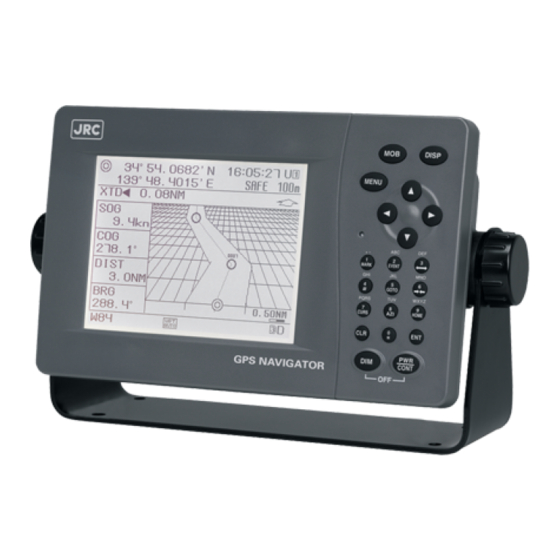
Section 2 Names and Functions of Each Unit 2.1 NWZ-4740 DISPLAY UNIT Unit (Front) Operation panel Buzzer Display Information received from the GPS receiver, the equipment setting Control Panel screen, etc. are displayed. Name Function MOB key Displays the plotting screen, and stores the location where a crewmember/passenger has fallen in the sea DISP Display key... - Page 32 Reading the Display The symbols and characters that appear in fixed locations on the screen are described below. RAIM Displays the preset accuracy level Navigator number In operation: Main display unit: Displays only the navigator number. RAIM OFF : Sub display unit: and S followed by the subsequent No faulty satellite: numbers are displayed.
-
Page 33: Jlr-4341 Dgps Sensor
2.2 JLR-4341 DGPS Sensor Radome 6Pins Connector Approx. φ19 mm Base Mounting Screw 1inch 14UNS-2B Data Cable 15m Approx. φ6mm 2.3 JLR-4340 GPS Sensor Radome 6Pins Connector Approx. φ19 mm Base Mounting Screw 1inch 14UNS-2B Data Cable 10m Approx. φ6mm... -
Page 35: Section 3 Display Screen
Section 3 Display Screen Each screen is detailed in this section. 3.1 Display screen The screen is switched each time is pressed. Users are allowed to set the screen displayed when the power is turned on. Users can also determine not to display unnecessary screens. -
Page 36: Cdi Screen
Plotting screen 2 Plotting screen 3 This screen graphically displays the own ship's position in full-screen mode. CDI screen This screen graphically displays the CDI, course, speed, and leg. The highway screen can be displayed by pressing and/or GPS information screen This screen displays... - Page 37 GPS information screen Waypoint information screen This screen displays the information of waypoints on the route. The information of the next waypoint can be displayed by pressing and/or Beacon information screen This screen displays information received with the beacon receiver. Navigation assistance screen This screen displays information such as the leg and time.
- Page 38 3.1.1 Navigation Information Screen The navigation information screen displays the position, speed, and course of the own ship. If there are waypoints, the target waypoint number and estimated arrival time are displayed. The sub-screens can be displayed by pressing and/or The sub-screens vary depending on the presence or absence of waypoints.
- Page 39 Memo VTD (Speed of the destination component) VTD (An acronym of "Velocity Toward Destination) This in an index that shows how fast the boat is approaching toward the destination in the unit of knot when it is navigation at a given bearing angle and speed. VEAR(Speed of the COG component) VEAR(An acronym of "Velocity Along Route") This in an index that shows how fast the vessel is approaching along the planned route in...
- Page 40 (2) If there are no waypoints: If there are no waypoints, only the position, speed, and course of the own ship are displayed. Main screen ( 3 digit position screen) Own ship's position (latitude and longitude) Course Speed Sub-screen 1 ( 4 digit position screen) Own ship's position (latitude and longitude) Course...
- Page 41 3.1.2 Plotting Screen 1 The plotting screen 1 displays the course, speed, bearing, and distance at the bottom of the screen. (Refer to "4.3 PLOT SCREEN OPERATION".) There are three types of plotting screens, and all the plotting screens display the same information.
- Page 42 3.1.5 CDI Screen The CDI screen can graphically display the CDI, course, speed, and leg. The highway screen can be displayed by pressing and/or If the heading is input, and heading (HDG) is displayed. Time Own ship's position CDI screen Leg distance indicator bar (latitude and longitude) : Traveled distance...
-
Page 43: Beacon Information Screen
3.1.6 GPS Information Screen The GPS information screen displays the receiving status of GPS satellites and beacon. GPS satellite number Unframed: Search GPS satellite location : Completion of and the receiving status demodulation Unframed: Search : Use of position fixing : Completion of GPS signal intensity bar demodulation... -
Page 44: Navigation Assistance Screen
3.1.9 Navigation Assistance Screen The navigation assistance screen calculates and displays navigation information such as the navigation start and end, leg distance, and total time. (Refer to "4.12 NAVIGATION ASSISTANCE".) The trip calculation screen, the external equipment display screen, and the screen for calculating the distance/bearing between two points can be displayed by pressing and/or Navigation assistance screen 1... -
Page 45: Section 4 Operation
Section 4 Operation 4.1 Menu List Main Menu Sub Menu Sub Menu Range Reference 1.DISPLAY 1.CONTRAST 1-7-13 4.14.1 2.DIMMER 1-9-10 4.14.2 -MAXIMUM- -TYPICAL- 1-6-10 -MINIMUM- 1-4-10 5.CLICK SOUND ON/OFF 4.14.3 6.REVERSING NORMAL/REVERSE1 4.14.4 MODE / REVERSE2 7.INPUT ASSIST ON/OFF 4.14.5 8.DISPLAY SELECT 1.NAV ON/START/OFF... - Page 46 Main Menu Sub Menu Sub Menu Range Reference 3.WPT/ROUTE 1.ENTRY WPT/ 4.4.1/4.4.2 WPT LIST 2.MAKE ROUTE/ 4.5.1/4.5.2 ROUTE LIST 3.ROUTE 1.LEG CHANGE AUTO/MANUAL 4.6.1/4.6.3.2 START/END 2.DIRECTION ORDER/REVERSE 3.NAVIGATION START/END 4.COPY 1.WPT COPY 4.4.5 WPT/ROUTE 2.ROUTE COPY 4.5.4 5.DELETE 1.WPT DEL 4.4.6 WPT/ROUTE 2.ROUTE DEL...
- Page 47 Main Menu Sub Menu Sub Menu Range Reference 5.SYSTEM 1.TIME DIFF 4.15.1 -13:30-13:30 2.DATE DISP 'YY-MM-DD/ 4.15.2 DD MM,'YY/ MM DD,'YY 3.TIME DISP 24hr/12hr 4.15.3 4.DATUM WGS84 etc. 4.15.4 5.UNIT - NM,kn 4.15.5 DIST/SPEED km,km/h mi,mi/h 6. HEIGHT, DEPTH m/ft/fm 4.15.6 7.
- Page 48 1.DEMO TYPE STATIC/ 4.20.6 STRAIGHT / RIGHT/LEFT/ ROUTE/AUTO 2.DATE 3.TIME 4.LATITUDE 5.LONGITUDE 6.SPEED 7.COURSE 8.RADIUS 9.ROUTE 0.START 7.DATA I/O 1.DATA IN/OUT1 NMEA/JRC/IEC/ 4.20.7.1 ROUTE/SWITCH/ PRINTER 2.DATA OUT2 NMEA/JRC/IEC/ 4.20.7.2 ROUTE/SWITCH 3.DATA OUT3 NMEA/JRC/IEC/ 4.20.7.3 ROUTE/SWITCH 4.DATA IN/OUT4 NMEA/JRC/IEC/ 4.20.7.4/ ROUTE/SWITCH/ 4.20.7.8 EXT EQUIP 5.CONTACT OUTPUT...
-
Page 49: Basic Operation
4.2 Basic Operation 4.2.1 Turning the Unit On Press the button to turn the unit power on. System initialization will start. Once initialization has been completed, self-diagnosis will start, and once the equipment's status has been confirmed, the screen will switch to the standard screen. Attention If the unit cannot be turned on, check the main power supply and the connection of display unit cable. -
Page 50: Startup (Error-1)
If any of the self-diagnosis results are "NG", the results are displayed. The unit does not switch to the standard screen unless the key is pressed. Attention If any errors (NG) are detected, please contact JRC or an affiliate. 4.2.1.3 Startup (Error-2) Messages shown below may be displayed during sensor diagnostics. -
Page 51: Startup (Error-3)
Startup (Error-3) If the following screen is displayed after the unit is turned on, press the key and key simultaneously to turn off the power. Attention Contact JRC or its affiliate. 4.2.2 Turning the Unit Off If the key and key are pressed and held down simultaneously, the power will be turned off and the screen display will turn off. -
Page 52: Adjusting The Backlight
4.2.3 Adjusting the Backlight The brightness of the display can be set to one of four levels (bright, medium, dark, off). The brightness is set to medium when the unit is turned on. The brightness cycles in the following order when the button is pressed: Bright →... -
Page 53: Stopping The Alarm Buzzer
4.2.5 Stopping the Alarm Buzzer The buzzer can be stopped by pressing the key. The buzzer sounds when one of the following occurs. · Position measurement is interrupted · An error occurs Memo · Mutual Acknowledgement Function When positioning is stopped and the buzzer sounds, the mutual acknowledgement function can be used to stop the buzzer from another unit. -
Page 54: Plot Screen Operation
4.3 Plot Screen Operation 4.3.1 Cursor Operation Cursor Information Cursor Latitude and Longitude Cursor Distance from Own ship to Cursor Bearing from Own ship to Cursor Own ship 4.3.1.1 Displaying the Cursor · Cursor display can be turned off and on. ·... -
Page 55: Centering The Cursor Position
4.3.1.3 Centering the Cursor Position · The position of the cursor can be displayed at the center of the screen. Procedure Display the cursor. Move the cursor to the point on the screen which you want to be centered. Press The position the cursor was at will be moved to the center of the screen. -
Page 56: Zooming The Screen In And Out
4.3.3 Zooming the Screen In and Out · The plot screen width can be changed to any of the widths below. 0.2, 0.5, 1.0, 2.0, 5.0, 10.0, 20.0, 50.0, 100.0, 200.0, 300.0[NM] Procedure Each time is pressed, the screen will zoom in (a narrower area will be displayed). Each time is pressed, the screen will zoom out (a wider area will be displayed). -
Page 57: Waypoint Symbol Display
4.3.6 Waypoint Symbol Display · The symbols and numbers of waypoints registered in the waypoint list are displayed on the plot screen. · Up to 1000 waypoints can be displayed on one screen. · To turn off waypoint symbol display, set "WPT" to "OFF" as described in "4.3.12 Hiding Plot Screen Symbols". -
Page 58: Editing Waypoint Symbols
4.3.6.2 Editing Waypoint Symbols · Waypoint symbol shapes and comments can be edited, but the symbols on the active route or sharing route can not be edited. · Waypoint symbols can also be edited from the menu. Please refer to "4.4.4 Editing Waypoint Information". -
Page 59: Deleting Waypoint Symbols
4.3.6.3 Deleting Waypoint Symbols Waypoints can be deleted. Deleted waypoints will also be deleted from the waypoint list. However, waypoints on the active route will be deleted from the route, but will not be deleted from the waypoint list (skip). For details regarding skipping, refer to "4.3.7.3 Skipping Route Waypoints". -
Page 60: Displaying Route Information
4.3.7.1 Displaying Route Information If the cursor is moved onto a route, and left in place for 1 second or longer, the route information will be displayed. If the cursor is moved off the route, the route information will be hidden. The route information displayed consists of the route number and comments. -
Page 61: Skipping Route Waypoints
4.3.7.3 Skipping Route Waypoints Waypoints on routes can be skipped. Waypoints on sharing route can not be skipped. If skipped, they will disappear from the route, and a route connecting the previous and next waypoints will be created, but the waypoint will not be deleted from the route planning. Skipping is also possible from the menu. -
Page 62: Track Display
4.3.8 Track Display · The own ship's track can be displayed. · A maximum of 2000 points of track can be stored. Once this number is exceeded, old track points will be automatically deleted. · To turn off track display, set "TRACK" to "OFF" as described in "4.3.12 Hiding Plot Screen Symbols". -
Page 63: Changing Track Line Type
4.3.8.2 Changing Track Line Type The track line type (dots, line, dotted line) can be selected. Procedure Press , and then and select "TRACK". Press to select the line type, and press Line Type List 4.3.8.3 Deleting Tracks All tracks can be deleted. Partial deletion cannot be performed. -
Page 64: Event And Mark Symbol Display
4.3.9 Event and Mark Symbol Display · Events and marks registered in the event/mark list can be displayed on the plot screen. Event: When the event key is pressed, a symbol is displayed at the own ship's position, and is registered in the event/mark list. -
Page 65: Changing Event/Mark Shapes
4.3.9.3 Changing Event/Mark Shapes The default symbol types of events and marks displayed when setting events or marks can be selected. Individually selected symbol types are not changed. Procedure (1) Changing Event Symbol Shape Press , and then , and select "EVENT". Press to select the shape, and press (2) Changing Mark Symbol Shape... - Page 66 Event Information Symbol Event/Mark Number Comment Event Position Entry Date/Time Cursor Water Temperature Water Depth Event Symbol Current Event Information Symbol Mark Information Event/Mark Number Comment Mark Position Entry Date/Time Cursor Mark Symbol Mark Information Memo · Event and mark information can also be displayed from the event/mark list. Please refer to "4.7.3 Editing Event and Mark Information".
-
Page 67: Editing Event/Mark Information
4.3.9.5 Editing Event/Mark Information Event and mark symbol shapes and comments can be edited. Procedure Procedur Press , and display the cursor. Press to move the cursor to the event or mark symbol, and the event or mark information will be displayed. Press to display the edit screen. -
Page 68: Registering Event/Mark Positions To The Waypoint List
4.3.9.6 Registering Event/Mark Positions to the Waypoint List Event and mark positions can be registered to the waypoint list. This enables them to be used as waypoints. Procedure Press , and display the cursor. Press to move the cursor to the event or mark symbol you wish to register to the waypoint list, and display the event or mark information. -
Page 69: Line Display
4.3.10 Line Display · Lines can be drawn between any two points on the plot screen. · To turn off line display, set "LINE" to "OFF" as described in "4.3.12 Hiding Plot Screen Symbols". 4.3.10.1 Drawing Lines The cursor is used to set start and end points on the plot screen, and a line is drawn connecting them. -
Page 70: Deleting Lines
4.3.10.2 Deleting Lines If an inflection point on a line is deleted, the inflection points before and after it will be connected. Entire lines can also be deleted. Procedure Press , and display the cursor. Press to move the cursor to the inflection point you wish to delete, and display the mark information. -
Page 71: Changing Line Types
4.3.10.3 Changing Line Types The line type can be changed. Line types can be set for each line, but cannot be changed after the line has been set. Procedure Press , and then , and select "LINE". Press to select the line type, and press Line Type List 4.3.11 Own Ship Display ·... -
Page 72: Hiding Plot Screen Symbols
4.3.12 Hiding Plot Screen Symbols · Individual symbols on the plot screen can be hidden. · Set symbols to "OFF" to hide them. · Set symbols to "ON" to display them. · The following symbols can be set: Waypoints, waypoint numbers, marks, events, event / mark numbers, tracks, lines, arrival circles, route widths, scale bars, symbol information, cursor position information, grid lines, grid latitude, grid longitude. -
Page 73: Registering Waypoints
4.4 Registering Waypoints · Waypoints must be registered to the waypoint list to start navigation. · Up to 10000 waypoints can be registered in this unit. · The waypoint list is divided into 3 regions, managed via numbering from 1 - 11024. 1 - 10000: Waypoints registered in this unit. -
Page 74: Registering Waypoints
4.4.2 Registering Waypoints The following 5 positions can be registered in the waypoint list. (1) Own ship position (2) Specified latitude and longitude (3) Cursor position (4) Position defined by a bearing and distance from a specified point (5) A position registered in the event/mark list Up to 10000 points can be registered. -
Page 75: Registering The Own Ship Position
4.4.2.1 Registering the Own Ship Position The own ship position can be registered to the waypoint list. Procedure Please refer to "4.4.2 Registering Waypoints" and display the waypoint registration screen. Press "POSITION". Press and move the cursor to "OWN SHIP", and then press The ship's position is shown in "5. -
Page 76: Registering The Cursor Position
4.4.2.3 Registering the Cursor Position Any cursor position on the plot screen can be registered to the waypoint list. Procedure Please refer to "4.4.2 Registering Waypoints" and display the waypoint registration screen. Press "POSITION". Press , move the cursor to "CURSOR", and press The plot screen will be displayed. - Page 77 (2) When "OWN SHIP" is Selected The ship's position is shown in "2. START LAT", "3. START LON". (3) When "CURSOR" is Selected The plot screen will be displayed. Press to move the cursor, and press at the position you wish to register.
-
Page 78: Registering From The Event/Mark List
4.4.2.5 Registering from the Event/Mark List Positions registered in the event/mark list can be registered as waypoints. Procedure Please refer to "4.4.2 Registering Waypoints" and display the waypoint registration screen. Press "POSITION". Press , move the cursor to "EVENT LIST", and press The event/mark list will be displayed. -
Page 79: Editing Waypoint Information
4.4.4 Editing Waypoint Information · Registered waypoint information (symbol shape, comment, waypoint position) editing can be performed. · Waypoints on routes which are currently being executed cannot be edited. Procedure Press , and then , and display the waypoint list. Move the cursor to the waypoint number you wish to edit. -
Page 80: Copying Waypoint Information
4.4.5 Copying Waypoint Information · Waypoint information can be copied to another waypoint number. Event and mark information can also be copied to the waypoint list. HOME is treated as number 1 on the waypoint list. · The waypoints used by the shared active routes received from ECDIS, which are stored in number 10001 - 10512, are automatically overwritten when the next route is received. - Page 81 (3) When "WPT No." is Selected Use the numeric keypad to select the waypoint number to be copied, and press (4) When "FROM TO" is Selected Multiple waypoint numbers can be copied. Use the numeric keypad to enter the start and end point waypoint numbers, and press The cursor will move to the "COPY DEST", so press Copy Origin Start...
- Page 82 The cursor will move to the "COPY", so press Start of Copy Destination If there is insufficient continuous free space at the copy destination, the following will be displayed. Press to select the copy method, and press The following is an overview of the display. ALL OVER WRITE :Overwrites from selected copy destination.
-
Page 83: Deleting Waypoints
4.4.6 Deleting Waypoints · Waypoints registered between 1 and 10000 can be deleted. · Waypoints on routes which are currently being executed cannot be deleted. · When a waypoint on a route which is not currently being performed is deleted, it will be deleted from the route as well. -
Page 84: Route Planning
4.5 Route Planning · Routes can be made from registered waypoints. · A maximum of 100 routes can be created with this unit, with each route having up to 512 waypoints. Route widths, arrival circle radii, GC/RL, and other waypoint information can be set for each LEG. - Page 85 Required time from ship position to Distance from ship position to cursor specified waypoint cursor specified waypoint Up / Down Scroll Cursor No display : Use Position SKIP: Skip Waypoint LEG distance calculation methods: LEG Information Screen R: Rhumb line G: Great circle LEG distance Bearing from previous...
-
Page 86: Creating Routes
Memo · Great-Circle Sailing: The shortest distance from the current position to the waypoint can be used, but the bearing will be different from that determined on a nautical chart, and will change during movement. · Rhumb line Sailing: Sailing can be performed directly from the current position to the waypoint, without changing bearing. -
Page 87: Editing Routes
Enter a comment. Use the up and down keys to move the cursor to the comment entry field, and press The unit will enter comment entry mode. Enter the comment. Please refer to "4.9 Entering Comments" for instructions on how to enter comments. Comment Entry Field Move the cursor to the comment entry field Comment Entry Mode... -
Page 88: Adding Route Waypoints
4.5.3.2 Adding Route Waypoints Waypoints can be added at any position along routes. Procedure Please refer to "4.5.1 Displaying the Route List", select the route to which you wish to add a waypoint, and display the LEG information. LEG Information Screen Move the cursor to the position where you wish to perform addition. - Page 89 Ex 2) Adding a waypoint at the start cursor Move to first waypoint Waypoint List Ex 3) Adding a waypoint at the end Move cursor to after last waypoint Waypoint List Move the cursor to the waypoint number you wish to register, and press Refer to "4.8.1 Moving the Cursor within a List"...
-
Page 90: Copying Routes
4.5.4 Copying Routes · Routes which have been created can be copied to different route numbers. · The waypoints used by the shared active routes received from ECDIS in number 101 are automatically overwritten when the next route is received. Routes which you wish to retain must be copied to a number between 1 and 100. - Page 91 (4) When "FROM TO" is Selected Multiple route numbers can be copied. Enter the start point and end point with the numeric keypad, and press The cursor will move to the "COPY DEST", so press Copy Origin Start Copy Origin End Copy Quantity Press to select the copy destination, and then press...
-
Page 92: Deleting Routes
The following is an overview of the display. ALL OVERWRITE: Overwrites from selected copy destination. Overwriting cannot be performed for active routes. In this case, "ALL OVER WRITE" is not displayed. TO EMPTY AREA: Copying is performed to a different empty area: When there are no empty area in list, "TO EMPTY AREA"... -
Page 93: Sharing Routes With Ecdis
(3) When "ROUTE No." is Selected Enter the route number with the numeric keypad, and press Press to select whether the waypoint is deleted, and the press The following is an overview of the waypoint deletion submenu. (1) ROUTE: Only the route is deleted. (2) ROUTE + WPT: The route as well as the waypoint used on the route are deleted. - Page 94 When "UNICAST" is selected, press to select the Destination IP "TO IP" and "PORT No.". Press "FORMAT". Press to select "SHARE ROUTE", and press Press "OUT TYPE". 10. Press to select the output data, and press The following is an overview of the output data submenu. (1) ALL: Output all routes between 1 and 101.
-
Page 95: Sharing Active Routes
4.5.6.2 Sharing Active Routes If a route is switched on this unit or on ECDIS when sharing the active route, the connecting equipment's route will also switch. Sharing must be enabled to share active routes. The following is an overview of the active route sharing configuration submenu. (1) SHARE1: If the active route is switched on the unit, the route will automatically be sent out to connected equipment. - Page 96 Route Reception Route switching occurs automatically. (3) SHARE 3 Active Route Sharing Route Start / Output Start the route as directed in "4.6 Performing Navigation". LAN route output starts automatically. Route Reception When an active route is received, the following is displayed. Select "YES"...
-
Page 97: Setting Route Default Settings
4.5.7 Setting Route Default Settings · The route default value is applied to routes created via GOTO. · The following is an overview of the route default settings submenu. (1) WIDTH PORT: The port route width can be set. (2) WIDTH STBD: The starboard route width can be set. -
Page 98: Performing Navigation
4.6 Performing Navigation · Registered and temporary routes can be started. · Navigation can be performed via the following methods. (1) Selecting a route from the route list (2) Selecting a waypoint with the GOTO key (3) Selecting a route with the GOTO key (4) Creating a route with the GOTO key ·... - Page 99 MANUAL: Switching to the next waypoint is performed manually. displayed in the status bar. When the arrival circle is reached, the arrival alarm sound configured in the alarm settings will be sounded, and the following will be displayed. Press to stop the alarm and update the waypoint. (2) DIRECTION: You can set whether to navigate in the order of the waypoints, or to navigate starting from the final waypoint.
-
Page 100: Starting Navigation With The Goto Key
4.6.2 Starting Navigation with the GOTO Key · If a waypoint or route is selected with the GOTO key, navigation starts to that waypoint. · If a waypoint on the active route is selected with the GOTO key, navigation restarts from that waypoint. - Page 101 (3) Select a route number If you know the route number, you can enter the number to set the route. Press and then Enter the route number, and press The route start / end screen will be displayed, so perform route settings. Please refer to "4.6.1 Selecting a Route from the Route List"...
- Page 102 If you don't wish to register the route in the route list, select "No" and press Navigation will start without route registration. If you wish to register the route in the route list, select "Yes" and press . The route list will be displayed.
- Page 103 Ex) To restart the route from waypoint number 0004. Enter waypoint 0004 on the route with the GOTO key. Restart the route from waypoint 0004. Active route 4-59...
-
Page 104: Stopping Navigation
4.6.3 Stopping Navigation · Navigation currently underway can be stopped. · To end the navigation, there are two methods: selecting in the menu and holding down 4.6.3.1 Ending Navigation with GOTO key · Operation can be performed on any screen other than the menu, waypoint information, navigation assistance 4 screen. -
Page 105: Events/Marks
4.7 Events/Marks · Events, marks, MOB, and lines are all registered in the event/mark list. 4.7.1 Displaying Events/Marks · A list of all registered events and marks can be displayed. · MOB is registered as event number 000. Event/Mark number Number of selected by cursor Entries... -
Page 106: Editing Event And Mark Information
4.7.3 Editing Event and Mark Information · Registered event (including MOB) and mark information (symbol, comment) can be edited. Procedure Display the event or mark information to be displayed using the procedure given in "4.7.2 Event and Mark Information Display". (1) To Change the Symbol Shape Press "SYMBOL". -
Page 107: List Screen Operation
4.8 List Screen Operation · This unit displays waypoints, events, marks, and routes in list form. · All lists use the same operating procedures. 4.8.1 Moving the Cursor within a List · The cursor can be moved within a list in the following ways: (1) The cursor can be moved via the directional keys (2) The cursor can be moved by entering a number with the numeric keypad These function for cursor operation in all lists. -
Page 108: Using The Numeric Keypad To Enter A Number And Move The Cursor
4.8.1.2 Using the Numeric Keypad to Enter a Number and Move the Cursor The operation examples show selection of waypoint 5 in the waypoint list, but the instructions provided apply to operation within all lists. Procedure Display the list. Enter the destination number "5" with the numeric keypad, and press The cursor moves to number 5. -
Page 109: Jumping To An Unused Number
4.8.2.2 Jumping to an Unused Number The cursor can jump to the nearest unused number (unregistered number) in a list. This can be used when you want to register an item, but do not know of an unused number. Procedure Display the list. -
Page 110: Using The Numeric Keypad To Enter A Number And Move The Cursor
4.8.2.3 Using the Numeric Keypad to Enter a Number and Move the Cursor The operation examples show selection of waypoint 7 in the waypoint list, but the instructions provided apply to operation within all lists. Procedure Display the list. Enter the destination number "7" with the numeric keypad, and press The cursor moves to number 7. -
Page 111: Selecting A Range Within A List
4.8.3 Selecting a Range within a List · The following methods can be used to select a range in a list: (1) The cursor can be moved via the up and down keys to select the start and end points (2) The cursor can be moved by entering a number with the numeric keypad to select the start and end points ·... -
Page 112: Moving The Cursor With The Numeric Keypad And Selecting A Range
4.8.3.2 Moving the Cursor with the Numeric Keypad and Selecting a Range The operation examples show selection of waypoints 2 to 5 in the waypoint list, but the instructions provided apply to operation within all lists. Procedure Display the list. Use the numeric keypad to enter number "2"... -
Page 113: Entering Comments
4.9 Entering Comments · Comments of up to 16 characters can be added to waypoints, events, marks, and routes. · Characters are assigned to the numeric keypad, and can be entered by pressing the keypad keys. · If the display language is set to Japanese, katakana entry can be performed. ·... - Page 114 The "o" in "Tokyo" is assigned to numeric keypad number 6, so press Press until an "o" is displayed at the cursor position in the comment field. The "k" in "Tokyo" is assigned to numeric keypad number 5, so press Press until a "k"...
-
Page 115: Deleting Text
4.9.2 Deleting Text · Letters and characters in comments can be deleted. Procedure to move the cursor to the letter or character which you wish to delete. Press Move the cursor to the "r" position The "r" is deleted 4.9.3 Adding Text ·... -
Page 116: Displaying Characters Assigned To The Numeric Keypad
4.9.4 Displaying Characters Assigned to the Numeric Keypad · Characters assigned to numeric keypad keys can be displayed on screen. · The characters are displayed onscreen in the same positions as they are on the numeric keypad, allowing you to match their positions. Procedure Press , and then... -
Page 117: Mob
4.10 MOB · The MOB (Man Overboard) function is used to save the position at which a person or object has fallen overboard. This allows rapid return to that location. · The MOB function is valid on all screens. · When MOB is performed, the plot screen is automatically displayed, a MOB mark is displayed at the point where the man overboard occurred, and the distance and direction from the current position to the man overboard position is displayed. -
Page 118: Alarm Settings
4.11 Alarm Settings 9 types of alarms can be configured. The can be individually turned off or on, and the alarm sounds can be set individually. The following alarms can be configured. (1) SYSTEM: An alarm sounds when positioning is stopped. This cannot be set to Off. (2) ARRIVAL/ANCHOR: An alarm sounds when own ship reaches or leaves the arrival circle. - Page 119 (1) ARRIVAL/ANCHOR Press "ARRIVAL/ANCHOR". Press to select "ARV", "ANC", or "OFF", and press An alarm will sound when own ship enters or exits the arrival circle set for the course. If no arrival circle is set, then an alarm will sound when own ship enters or exits the default course value arrival circle radius.
- Page 120 (3) DGPS Press "DGPS". Press to select "OFF" or the alarm trigger state, and press ON → OFF: An alarm will sound when DGPS positioning switches to GPS positioning. OFF → ON: An alarm will sound when GPS positioning switches to DGPS positioning. ON ↔...
-
Page 121: Setting Alarm Sounds
(8) SPD 21. Press "SPD". 22. Press to select "OFF" or "RANGE", and press 23. Enter the speed with the numeric keypad, and press OVER: An alarm will sound when the speed exceeds the set value. UNDER: An alarm will sound when the speed falls below the set value. IN RANGE: An alarm will sound when the speed is within the set range. -
Page 122: Navigation Assistance
4.12 Navigation Assistance 4.12.1 Measuring the Trip Distance and Time During Navigation (Navigation Assistance 1) · Navigation Assistance 1 shows the time when measurement started, the time measurement ended, the total time, and the total distance over ground. If the speed through water is input from external equipment, the distance through water is also displayed. -
Page 123: Measuring The Trip Distance And Time (Navigation Assistance 2)
4.12.2 Measuring the Trip Distance and Time (Navigation Assistance 2) · Navigation Assistance 2 shows the time when measurement started, the time measurement ended, the total time, the average speed during measurement, and the distance over ground. If the speed through water is input from external equipment, the speed through water is also displayed. -
Page 124: Measuring The Distance And Bearing Between 2 Points (Navigation Assistance 4)
4.12.3 Measuring the Distance and Bearing Between 2 Points (Navigation Assistance 4) · Navigation Assistance 4 allows you to specify a start point and an end point, and calculate the distance and bearing between the two points. · The start and end points can be selected from the following 5 items. (1) Own ship’s position (2) Specified latitude and longitude (3) Cursor position... -
Page 125: Beacon Information
4.13 Beacon Information When the beacon information is set to "ON" based on "4.16.8 Setting Beacon/SBAS", the beacon information (Type 16 message) from the beacon broadcast stations can be displayed. Please refer to "4.20 Equipment Configuration" and switch the unit to equipment configuration mode. -
Page 126: Display Settings
4.14 Display Settings If "1.DISPLAY" is selected on the main menu, the display menu will be displayed. On the display menu, you can set the contrast, dimmer, click sound, reversed display, input assistance, and screen display. The following is an overview of each submenu. (1) CONTRAST: You can set the LCD contrast. -
Page 127: Setting The Click Sound
Memo · Set the highest value for "Bright", and the smallest value for "Dark". · The key brightness setting changes in accordance with the dimmer setting. 4.14.3 Setting the Click Sound · You can turn the key operation click sound on or off. ON: The click sound is enabled OFF: The click sound is disabled Procedure... -
Page 128: Input Assistance Settings
4.14.5 Input Assistance Settings · Input assistance display can be turned on or off. ON: Input assistance display enabled OFF: Input assistance display disabled Procedure Press , and then to select "INPUT ASSIST". Press to select "ON" or "OFF", and press 4.14.6 Selecting the Display Screen ·... -
Page 129: System Settings
4.15 System Settings · Select "5. SYSTEM" on the main menu to display the system settings screen. The following is an overview of each submenu. (1) TIME DIFF: To display the time at the current location, enter the difference between the local time and UTC. -
Page 130: Setting The Time Display
4.15.3 Setting the Time Display · You can select 24 hour or 12 hour time display. · Please refer to "4.20 Equipment Configuration" and switch the unit to equipment configuration mode. Procedure Press , and then to select "TIME DISP". Select the display format with , and press 4.15.4 Setting the Geodetic System... -
Page 131: Setting Temperature Units
Enter calculated value and press To keep the default value, or restore the unit to the default value, select "DEFAULT". 4.15.7 Setting Temperature Units · You can set the temperature unit to ºC or ºF. · Please refer to "4.20 Equipment Configuration" and switch the unit to equipment configuration mode. -
Page 132: Setting The Maximum Analogue Speed Meter Value
4.15.9 Setting the Maximum Analogue Speed Meter Value · You can set the maximum value of the CDI screen analogue speed meter. · Set the value to one appropriate for the ship in which the unit is installed. The maximum value is 100 kn. -
Page 133: Gps/Beacon/Sbas Settings
4.16 GPS/Beacon/SBAS Settings · Select "6. GPS/BEACON/SBAS" on the main menu to display the GPS/beacon/SBAS settings screen. The items which can be set will vary depending on the connected sensor. The following is an overview of each submenu. (1) GPS MODE: You can select AUTO (JLR-7800 only), GPS Alone, Beacon, or SBAS. (2) FIX MODE: You can select AUTO, 3D, or 2D. -
Page 134: Setting The Fixing Mode
4.16.2 Setting the Fixing Mode · You can set Fix mode to AUTO, 3D, or 2D. · The selections are as follows: (1) AUTO: Positioning mode is automatically switched between 3D and 2D, with the optimal method being used. (2) 3D: 3D positioning is performed. -
Page 135: Setting Position, Speed, And Course Smoothing
4.16.5 Setting Position, Speed, and Course Smoothing · Smoothing can be applied to measured positions, speeds, and courses. · The higher the smoothing value, the smoother the results will be, but the greater the time lag. Conversely, if the smoothing value is set low, a great number of changes will occur, but there will be little time lag. -
Page 136: Initializing The Gps
Procedure Press , and then to select "RAIM ACCURACY LEVEL". Press to select the accuracy level value, and then press 4.16.7 Initializing the GPS · GPS initialization can be performed. · The submenus on the GPS initialization screen are as described below. (1) LATITUDE: Enter the approximate ship latitude. -
Page 137: Setting Beacon/Sbas
4.16.8 Setting Beacon/SBAS Beacon and SBAS settings can be performed. The sensor must support SBAS to perform SBAS settings. · The submenus on the beacon/SBAS settings screen are as follow. (1) STATION SELECT: Set the beacon station selection method. AUTO: The best beacon station is selected automatically from the GPS position. - Page 138 (3) Setting SBAS Satellites Press "SBAS SEARCH". Press to select the search method, and press If set to Manual, the SBAS satellite number can be selected. Press to select the SBAS satellite number, and press (4) Setting Type 0 Information Press "TYPE 0 INFORMATION".
-
Page 139: Setting Loran A/C
4.16.9 Setting LORAN A/C · Position displays and settings can be performed based on time differences. · Please refer to "4.20 Equipment Configuration" and switch the unit to equipment configuration mode. Procedure Press , and then to display the LORAN setting screen. Press "LORAN A/C". -
Page 140: Version Display
4.17 Version Display · The GPS sensor and display version number can be displayed. · The details of each submenu are shown below. (1) SENSOR (1-1) SERIAL No.: The serial number of the GPS sensor is displayed. (1-2) BARCODE: The GPS sensor barcode number is displayed. (1-3) VERSION: The GPS core version number is displayed. -
Page 141: Language Settings
4.18 Language Settings · Select "8. LANGUAGE" on the main menu to display the language settings screen. · You can select English or Japanese. · Please refer to "4.20 Equipment Configuration" and switch the unit to equipment configuration mode. Procedure Press , then to select "LANGUAGE". -
Page 142: Print
4.19 Print ・ When # key is pressed to print, ship information is printed on DPU-414 Printer. ・ To print with the # key is DPU-414 printer exclusive use. Please operate the printer when printing on NKG-84 Printer. · The # key can be used from any screen other than the menu screen, waypoint information screen, or Navigation Assistance 4 screen. -
Page 143: Equipment Configuration
4.20 Equipment Configuration · In order to change settings or perform installation configuration, you must switch the unit to equipment configuration mode. · When the unit is in equipment configuration mode, " " will be displayed at the top left of the title bar. -
Page 144: Setting The Display Type
4.20.1 Setting the Display Type · You can set whether the display is the main display connected to the GPS sensor, or a sub-display. · Set the display connected to the GPS sensor as "MAIN". · Set the display used as a sub-display as "SUB". Procedure Refer to "4.20 Equipment Configuration"... -
Page 145: Setting Sensor Position / Ccrp
4.20.3 Setting Sensor Position / CCRP · You can set the ship size, CCRP position, and GPS sensor position. · The CCRP position and GPS position are set on a coordinate system with the center of the ship as the point where the axes cross. ·... -
Page 146: Equipment Check
4.20.4 Equipment Check · An equipment check can be performed for the GPS sensor and the display. (1) Input port check (2) Self-diagnosis (3) Error log display and output (4) Setting value output 4.20.4.1 Input Port Check The display has 4 input ports (input from sensor, data IN1, IN4, and LAN). The data being received by each port can be displayed. -
Page 147: Displaying And Outputting Error Logs
If you wish to stop the operation, press Attention If the results were not good, contact JRC or its affiliate. 4.20.4.3 Displaying and Outputting Error Logs · Up to 100 recent errors can be displayed. They can also be output externally. -
Page 148: Performing A Master Reset (Reset)
4.20.5 Performing a Master Reset (Reset) · The GPS sensor, display, or both can be reset. · Resetting will restore all settings to their default values. · To reset the display, select "ALL" or "EXCEPT FOR LISTS". If "EXCEPT FOR LISTS" is selected, everything except the waypoint list, the route list, and the event / mark list will be reset. -
Page 149: Data I/O Settings
NMEA format data output. IEC: IEC format data output. JRC: JRC format data output. Fixed at 1200 bps. ROUTE: Output or input of memory route and waypoint data. Route and waypoint data can be sent to / from externally connected computers and equipment. -
Page 150: Configuring Data In/Out1
4.20.7.1 Configuring Data IN/OUT1 · NMEA, JRC, IEC, route WPT, automatic switch control data, and printer data can be output via data IN/OUT1. · To connect a DPU-414 printer, use a D-sub9 pin connector. Procedure Refer to "4.20 Equipment Configuration" and display the equipment configuration menu. - Page 151 (2) When "IEC" is Selected Select the bit rate, output sentence, and interval. Sentence and Interval Setting Screen The selected sentence is displayed. If no sentence has been selected, no sentence is displayed. If no sentence is displayed, the output sentence has not been selected. Press "SENTENCE".
- Page 152 Press "OUT TYPE", and select the data you wish to output. Output data types: · ALL WPT All waypoint data in the waypoint list is output as WPL sentences. · ALL ROUTE All route data in the route list is output as RTE sentences. ·...
- Page 153 Press "START" to display the following, and press "YES" to start data output. (4) Selecting "ROUTE" and receiving data Routes and waypoints are received from external sources as RTE and WPL sentences. Select the bit rate. Press "DATA IN/OUT". Press to select "IN", and then press Press "BITRATE", and select the bit rate.
- Page 154 (5) When "JRC" is Selected The bit rate is fixed at 1200 bps. (6) When "PRINTER" is Selected Data is output in dedicated printer format. Select the bit rate and output interval. The bit rate is selected at 4800bps for DPU-414 Printer.
-
Page 155: Setting Data Out2
4.20.7.2 Setting Data OUT2 · NMEA, JRC, IEC, route WPT, and automatic switch control data can be output via data OUT2. Procedure Please refer to "4.20 Equipment Configuration" and switch the unit to equipment configuration mode. Press , and then to select "DATA OUT2". -
Page 156: Setting Contact Output 1
4.20.7.5 Setting Contact Output 1 · The following contact outputs can be set for contact output 1: System, System + XTD + ARV, Log Pulse (200 pulse/NM), Log Pulse (400 pulse/NM), and Alarm ACK. · Please refer to "6.3 Cable Connection" for connection. The following is an overview of the contact output 1 submenu. -
Page 157: Setting Lan Settings
4.20.7.7 Setting LAN Settings · LAN configuration can be performed for active route sharing, data route sharing, data output, mutual monitoring, and remote maintenance output. · In data output, the output NMEA sentence can be selected. · To share active or data routes, sharing route configuration must be performed. Set the route sharing setting to "SHARE"... - Page 158 Procedure Refer to "4.20 Equipment Configuration" and display the equipment configuration menu. Press , then , and select "LAN". (1) Data route sharing setting Press to select "DATA ROUTE", and press Press to select "SHARE", and press Select "OFF" to disable sharing. Data Route Selection Screen (2) Active route sharing setting Press...
- Page 159 (3) Data output setting Press to select "DATA OUT", and press Press "CONNECT". Select the connection destination with , and press "MULTICAST", "UNICAST", or "BROADCAST" can be set as connection destinations. Normally, "MULTICAST" should be selected. When "UNICAST" is selected, destination IP "2. To IP" and "3. Port No." can be set. Press "FORMAT".
-
Page 160: Setting Tidal Current Meter Input
(5) Remote maintenance data output setting to select "REMOTE MAINTE", and press Press to select "ON", and then press Press "CONNECT". Select the connection destination with , and press "MULTICAST", "UNICAST", or "BROADCAST" can be set as connection destinations. Normally, "MULTICAST" should be selected. When "UNICAST"... -
Page 161: Setting The Ip Address
4.20.8 Setting the IP Address · The display's IP address, subnet mask, and default gateway can be set. The MAC address can be displayed. Procedure Refer to "4.20 Equipment Configuration" and display the equipment configuration menu. Press "IP". (1) IP ADDRESS Configuration Press "IP ADDR". -
Page 163: Maintenance And Inspection
WARNING Do not perform internal inspections or modifications of the equipment. Inspection or modification by unauthorized personnel may result in fire, electric shock, or equipment failure. Please consult with JRC or an affiliate to perform internal inspections or repair. CAUTION Use only the specified fuse. -
Page 164: Alarms
5.2 Alarms Refer to 4.2.7 and check if any alarm is given or not. If it is, check the details referring to the list shown below. Alarm List Message Message Contents Alarm Causes Number No Fix No Fix HDOP OVER HDOP value has been exceeded setting level GPS Antenna Open GPS Antenna Open(Sensor) -
Page 165: Troubleshooting
Do not perform internal inspections or modifications of the equipment. Inspection or modification by unauthorized personnel may result in fire, electric shock, or equipment failure. Please consult with JRC or an affiliate to perform internal inspections or repair. The following is reference information concerning identification of problems. -
Page 166: Repair Unit
5.3.3 Regular Replacement Parts Parts which should be regularly replaced are shown below. Contact JRC or an affiliate to order. Replace the radome and packing when replacing the lithium batteries. Please refer to "4.3 Entering Serial No./Barcode No.” in Service Manual and enter the Serial No. -
Page 167: Installation
Section 6 Installation Caution Please consult with JRC or an affiliate to perform installation. Installation by unauthorized personnel may result in malfunction. 6.1 GPS Sensor Installation 6.1.1 Selecting the Position for Installation Caution When connecting the cable attached to the equipment, do not bend it acutely, twist it, or impart excessive force. -
Page 168: Sensor Installation Procedure
6.1.2 Sensor Installation Procedure The sensor base contains 1 inch-14UNS-2B screw holes. It can be attached to poles with cut male screws, or off-the-shelf adapters. (1) When performing attachment, always hold and turn the sensor base. Holding and turning the radome may result in a large amount of force applied at the junction of the base and the radome, resulting in damage to the sensor. -
Page 169: Installation Of The Sensor On The Mast
6.1.3 Installation of the Sensor on the Mast Use a screw adapter (optional component or equivalent) to connect the sensor to the mast. The diagram shows the JLR-4341, but these instructions apply equally to the JLR-4340 as well. JLR-4341 DGPS Sensor Fitting Belt MPBP02520 Screw Adapter... -
Page 170: Installation Of The Sensor To Pass A Cable Through A Pole
6.1.4 Installation of the Sensor to pass a cable through a pole It is possible to pass a cable through a pole, when DGPS sensor attached to poles with cut male screws. (1inch-14 UNS-2A). In this case, Cable guard rubber (attached article) used. (1) The cable is installed as following figure. - Page 171 (3) When DGPS sensor attached to poles with cut male screws, round off the corners. round off the corners 25mm 1inch-14UNS-2A (4)When performing attachment, always hold and turn the sensor base. Holding and turning the radome may result in a large amount of force applied at the junction of the base and the radome, resulting in damage to the sensor.
-
Page 172: Display Unit Installation
6.2 Display Unit Installation 6.2.1 Selecting the Position for Installation Warning Install this unit at least 1 m away from any magnetic compasses. Installation near a magnetic compass may result in interference with the magnetic compass, and may result in an accident. Caution Use the indicated screws when installing the display unit to a stable wooden surface. -
Page 173: How To Flush Mount The Display
6.2.3 How to Flush Mount the Display Flush Mount (Connection with standard included components) Refer to the flush mount overview diagram to perform flush mount installation. Refer to the diagrams shown below for mount hole and installation space details. Leave space for maintenance after installation 180 or more (Unit: mm) - Page 174 Flush Mount (Connection with optional component) Leave space for maintenance after installation 180 or more (Unit: mm)
-
Page 175: Cable Connection
6.3 Cable Connection Unit (Rear Connectors) D-Sub Terminal Used to connect to a computer (RS-232C) or printer. CONTACT IN/OUT GPS/DGPS ETHERNET DATA IN/OUT External Equipment Connection Terminal (Ethernet) Used for ECDIS connection, etc. External Equipment Connection Terminal (Serial Transmission) Used for radar equipment connection, etc. Receiver Connection Terminal GPS/DGPS receiver connection. - Page 176 [Power Supply Connector] DC12/24V Power Cable: CFQ-7257 (Included) ① ② Terminal Name Explanation Number (CFQ-7252) 1 (Black) DCIN - Connect the included power cable. DC12/24V The voltage shall be 10.8 - 31.2 V DC. 2 (Red) DCIN + Connection Cable Appearance Cable Length: 2m CFQ-7257 Black...
- Page 177 [GPS/DGPS Connector] GPS/DGPS ① ⑤ ⑥ ② ④ ③ Terminal Name Explanation Number (CFQ-9000/ CFQ-9002) 1 (Red) GPS/DGPS Power to the sensor is supplied by the display unit. Power 2 (Black) 3 (White) RXD0 Receives data from the sensor. 4 (Green) 5 (Yellow) TXD0 Sends configuration data to the sensor.
- Page 178 Coaxial Cable Kit Connection When using a pre-existing coaxial cable, such as when switching from a JLR-6800, use a coaxial cable kit (NQD-4414). Coaxial Cable Kit/NQD-4414 DGPS Cable/CFQ-8919 Existing coaxial cable 6-12...
- Page 179 [Data IN/OUT Connector] DATA IN/OUT Data Cable: CFQ-5374 (Option) ① ⑧ ② ⑨ ⑦ ⑪ ⑫ ③ ⑩ ⑥ ④ ⑤ Terminal Name Explanation Number (CFQ-5374) 1 (Brown) Receives tide, water temperature, and water depth data, as well as alarm ACK. (Data IN4) 2 (Red) RXD4 (Refer to "5.19.7.8 Setting Tidal Current Meter Input"...
- Page 180 Connector Assembly (1) Prepare the cable to the following dimensions. 10mm (2) Assemble the included components in the following order. Housing Clamp Ring Lock Nut Sealing Nut Seal O-Ring Gasket Gasket installation direction Clamp Ring tightening torque: 1.2 - 1.5 kgf-cm Sealing Nut tightening torque: 1.3 - 1.8 kgf-cm 6-14...
- Page 181 [Contact Signal IN/OUT Connector] CONTACT IN/OUT Data Cable: CFQ-5404 (Option) ① ② ③ ④ ⑤ ⑥ ⑦ ⑧ ⑨ ⑩ ⑪ ⑫ ⑬ ⑭ Terminal Number Name Explanation (CFQ-5404) Unused Unused 7 (Purple) Outputs contact signal. Contact 8 (Grey) (Refer to "5.19.7.5 Setting Contact Output 1" for Output 1 configuration details) 9 (White)
- Page 182 [Ethernet Connector] ETHERNET Cable: CFQ-5473 A(Option) CFQ-5474 A(Option) 1 Pin 8 Pin Terminal Number Name Explanation (CFQ-5473) 1 (Orange/White) Outputs data. (Refer to "5.19.7.7 Setting LAN Settings" for 2 (Orange) configuration details) 3 (Green/White) Inputs data. (Refer to "5.19.7.7 Setting LAN Settings" for configuration details) 4 (Blue) 5 (Blue/White)
- Page 183 [RS232C Connector] This port is a dedicated port for updates and printer connection. Remove the two screws from the rear, remove the cover, and connect the cable. Perform printer configuration via Data IN/OUT1. Use a straight cable for updating, and a cross cable when connecting a printer. Female (S-type) Terminal Name...
-
Page 184: Optional Peripheral Connection
6.4 Optional Peripheral Connection 6.4.1 Sub Display Connection Connect the sub display sensor connection terminal to the main display external equipment connection terminal (serial). Use a junction box (CQD-10). Any main display external equipment connection terminal can be used. The following specifications apply to the terminal. -
Page 185: Junction Box Connection
6.4.2 Junction Box Connection Caution The junction box rubber gaskets (φ25 Gland side) fit φ 10 - 20 cables. How to Mount the Junction Box on a Flat Surface Securely mount the junction box on a given flat surface using self-tapping screws and flat washers as shown below. - Page 186 Pole Mounting Kit MPBP30608 Bracket SUS Hex Bolt M6 X 60 SUS Washer M6 SUS Spring Washer M6 SUS Nut M6 SUS Lock Nut M6 SUS Mast (φ26 - φ53) (Note) SUS: Stainless Steel To DGPS Sensor Gland φ15 Perform waterproofing ① or ② below for the glands.
-
Page 187: Coaxial Cable Kit Connection
Internal Connection Connect the respective cables (cable from the DGPS sensor and extension cable) to the terminals provided in the junction box as shown in the following figure. DGPS Sensor Junction Box DGPS Sensor Cable Line lengths: Terminal Cable 55±5 mm Black White Green... -
Page 188: Printer Connection
6.4.4 Printer Connection The RS-232C connector can be connected to the printer (DPU-414). The RS-232C connector can be configured via Data IN/OUT1.Set the Data IN/OUT1 data format to "Printer". The printer format data is output from RS-232C connector and also DATA IN/OUT connector No.3,4-pin. -
Page 189: Connecting Two Navigation Devices To A Printer
6.4.5 Connecting Two Navigation Devices to a Printer A switch (NCZ-777) is necessary when connecting 2 GPS units to printer (DPU-414). RS-232C connectors and printer (DPU-414) can be connected. The RS-232C connectors for both units are configured in Data IN/OUT1. The Data IN/OUT1 data format should be set to "printer". -
Page 190: Connecting 2 Gps Units To An Automatic Gps Select Switch
6.4.6 Connecting 2 GPS Units to an Automatic GPS Select Switch An automatic GPS select switch (NCZ-1537A) can be used to connect and automatically switch between two GPS units. The No. 1 GPS unit normally outputs data, but when it is not performing positioning, the No. - Page 191 6.5 LAN and Serial Connection This section contains representative examples of LAN and serial connections and settings. Please refer to "5.19.7 Configuring Data I/O" for details regarding configuration. The following connection conditions apply to the connection example. ・Two GPS units, 1 sub-display, and ECDIS are connected via LAN and are sharing routes ・The LAN is connected to remote maintenance ・Serial cabling is used to connect to the automatic GPS select switch and printer.
-
Page 192: Connection Diagram
DC OUT 1 Ø 60Hz AC IN 6.5V - 100V NOTE 220V 1. * DOCK SUPPLY *0.6/1kV-DPYC-1.5 DC OUT DC24V JRC SUPPLY (COPPER PLATE 0.3(T) x 25(W)) 12V - DC24V (From GMDSS CONSOLE) DOCK SUPPLY (COPPER PLATE 0.5(T) x 30(W)) 6-26... -
Page 193: After-Sales Service
Repairs to restore the proper equipment operation can be made at a specified rate with the user's consent. In this case, the equipment can either be sent to JRC or an affiliate, or on-ship repairs can be performed at a location specified by JRC or a sales affiliate. -
Page 195: Section8 Disposal
Section8 Disposal WARNING When disposing of the used lithium battery, place insulating tape over the battery terminals, or otherwise insulate the battery. Failure to do so may result in heating, explosion, or fire due to a shorted battery. 8.1 Disposal of the Equipment ●... -
Page 197: Specification
・Loran Conversion Function:Latitude and longitude can be converted into the Loran time difference. ・Display Language :Japanese or English ・Power Supply Voltage :DC12/24V(+30%,-10%) ・Power Consumption :less than 10W (JLR-7800) less than 9W (JLR-7500) less than 7W (NWZ-4740) ・Dimension :267.4(W)×162(H)×85(D)mm :Approximately 2.3Kg ・Mass *: External sensor must be connected. 9.1.2 Environment ・Operating Temperature :-15℃~+55℃... -
Page 198: External Interface
9.1.3 External Interface (1)Serial Transmission Channel Specification Notes DATA RS-422 Output NMEA,IEC,JRC IN/OUT1 RS-232C Input/Output - for PC or Printer DATA OUT2 RS-422 Output NMEA,IEC,JRC DATA OUT3 RS-422 Output NMEA,IEC,JRC DATA RS-422 Input NMEA External Equipment IN/OUT4 Output NMEA,IEC,JRC (1-1)NMEA ・Specification... -
Page 199: Jlr-4341 Dgps Sensor
9.2 JLR-4341 DGPS Sensor 9.2.1 Basic (1)GPS Unit ・Reception Method :Multi channel 12ch + SBAS 1ch ・Reception Frequency :1575.42MHz±1MHz(C/A code) ・Maximum Number of Tracked Satellites :12 satellites :13m 2DRMS (HDOP≦4 SA off) ・Accuracy 2DRMS (Beacon selected) 2DRMS (SBAS selected) ・SBAS :WAAS、MSAS、EGNOS ・Geodetic datum :Selection among 46 geodetic datum... -
Page 200: Jlr-4340 Gps Sensor
9.3 JLR-4340 GPS Sensor 9.3.1 Basic (1)GPS Unit ・Reception Method :Multi channel 12ch + SBAS 1ch ・Reception Frequency :1575.42MHz±1MHz(C/A code) ・Maximum Number of Tracked Satellites :12 satellites :13m 2DRMS (HDOP≦4 SA off) ・Accuracy 2DRMS (SBAS selected) ・SBAS :WAAS、MSAS、EGNOS ・Geodetic datum :Selection among 46 geodetic datum (2)Power Supply ・Power Supply Voltage... -
Page 201: Appendix
Appendix Appendix1 List of Geodetic System Screen Setting Geodetic System Display WGS-84 WGS-84 WGS-72 WGS-72 JAPAN Tokyo Datum NAD27 North American 1927 (USA) NAD27 North American 1927 (Canada, Alaska) EUROPE Europe 1950 (Europe) AUSTRA 66 Australian geodetic 1966 (Australia) OSGB-36 Ordnance Survey of Great Britain (England) NAD-83 NAD-83... -
Page 202: Appendix2 List Of Standard Terms, Units And Abbreviations
Appendix2 List of standard terms, units and abbreviations Term Abbreviation Term Abbreviation Acknowledge Change Acquire, Acquisition Circularly Polarised Acquisition Zone Clear Adjust, Adjustment Closest Point of Approach Compact Disk Read Only CDROM Memory Alarm ALARM Consistent Common CCRP Altitude Reference Point Amplitude Modulation Consistent Common CCRS... - Page 203 Term Abbreviation Term Abbreviation Distance Root Mean Square DRMS Geometric Dilution Of GDOP Precision Distance To Go Global Maritime Distress and GMDSS Drift DRIFT Safety System Dropped Global Navigation Satellite GNSS (for example, dropped EBL System origin) Global Orbiting Navigation GLONASS East Satellite System...
- Page 204 Term Abbreviation Term Abbreviation Interswitch Night Interval Normal NORM January North July North Up N UP June Not Less Than Label Not More Than Latitude Not Under Command Latitude/Longitude November Leeway October Limit Line Of Position Officer On Watch Offset OFFSET Long Pulse Long Range...
- Page 205 Term Abbreviation Term Abbreviation Radar Plotting Speed Radius Speed and Distance SDME Measuring Equipment Rain RAIN Speed Over the Ground Range Speed Through the Water Range Rings Stabilized STAB Raster Chart Display System RCDS Standby STBY Raster Navigational Chart Starboard/Starboard Side STBD Rate Of Turn Station...
- Page 206 Term Abbreviation Term Abbreviation Universal Time, Coordinated UTC Vessel Underway Using Engine Universal Transverse Mercator Video Unstabilised UNSTAB Visual Display Unit Variable Range Marker Voyage Variation Voyage Data Recorder Vector VECT Warning WARNING Very High Frequency Water Very Low Frequency Waypoint Vessel Aground GRND...
-
Page 207: Appendix3 Default Settings
Appendix3 Default Settings Main Menu Sub Menu Sub Menu Default 1.DISPLAY 1.CONTRAST 2.DIMMER -MAXIMUM- -TYPICAL- -MINIMUM- 5.CLICK SOUND 6.REVERSING NORMAL MODE 7.INPUT ASSIST 8.DISPLAY SELECT 1.NAV START 2.PLOT 1 3.PLOT 2 4.PLOT 3 5. CDI 6. GPS INFO 7.WPT INFO 8.BEACON INFO 9.NAV ASSIST 2.PLOT... - Page 208 Main Menu Sub Menu Sub Menu Default 3.ROUTE 1.LEG CHANGE START/END 2.DIRECTION 3.NAVIGATION 4.COPY WPT/ROUTE 1.WPT COPY 2.ROUTE COPY 5.DELETE 1.WPT DEL WPT/ROUTE 2.ROUTE DEL 6. TRANSFER 1.OUT / IN WPT/ROUTE (LAN) MULTICAST 2.CONNECT / FROM IP 0.0.0.0(at shipment) 3.TO IP 0(at shipment) 4.PORT No.
- Page 209 Main Menu Sub Menu Sub Menu Default 5.SYSTEM 1.TIME DIFF +00:00 2.DATE DISP DD MM,'YY 3.TIME DISP 24hr 4.DATUM WGS84 5.UNIT - NM,kn DIST/SPEED 6. HEIGHT, DEPTH 7. TEMPERATURE ℃ 8.MAG CORR 9.SPEED METER 50kn 6. GPS/BEACON/ 1.GPS MODE AUTO SBAS 2.FIX MODE AUTO...
- Page 210 Main Menu Sub Menu Sub Menu Default 0.EQUIP SET 1.DISPLAY TYPE MAIN 2.SENSOR No. 1(At shipment) 3. CCRP 1.SHIP DISABLE(At shipment) 2.BEAM 1.0m(At shipment) 3.LENGTH 1.0m(At shipment) 4.SENSOR DISABLE(At shipment) 0.0m(At shipment) 0.0m(At shipment) 7.CCRP DISABLE(At shipment) 0.0m(At shipment) 0.0m(At shipment) 4.CHECK 5.RESET 6.DEMO...
- Page 211 Main Menu Sub Menu Sub Menu Default 1.BITRATE 4800bps 2.SENTENCE GGA RMC VTG DTM ZDA APB RMB ACK (all interval 1s) ROUTE 1.BIT RATE: 4800bps 2.FORMAT: NMEA Ver2.3 3.OUT TYPE: ROUTE+WPT SWITCH 3.DATA OUT3 NMEA(default) 1.VERSION: Ver2.3 2.BIT RATE: 4800bps 3.SENTENCE: GGA RMC VTG DTM ZDA APB...
- Page 212 Main Menu Sub Menu Sub Menu Default EXT EQUIP 1.CURRENT LAYER-A LAYER:001 DATA No:ALL LAYER-B LAYER:002 DATA No:ALL LAYER-C LAYER:003 DATA No:ALL 5.CONTACT OUTPUT SYSTEM 6.CONTACT OUTPUT ALARM ACK 7. LAN ACTIVE ROUTE 1.CONNECT MULTICAST DATA ROUTE: SHARE MUTUAL:OFF 1.CONNECT MULTICAST DATA OUT : 1.CONNTECT:...
- Page 213 有毒有害物质或元素的名称及含量 (Names & Content of toxic and hazardous substances or elements) : JLR-7800/7500 形式名 名称 : GPS Navigator (Type) (Name) 有毒有害物质或元素 (Toxic and Hazardous Substances and Elements) 部件名称 (Part name) 铅 汞 镉 六价铬 多溴联苯 多溴二苯醚 (Pb) (Hg) (Cd) (PBB) (PBDE) GPS接收器...
- Page 216 For further information,contact: Not use the asbestos http://www.jrc.co.jp Marine Service Department Telephone : +81-3-3492-1305 Facsimile : +81-3-3779-1420 e-mail : tmsc@jrc.co.jp AMSTERDAM Branch Telephone : +31-20-658-0750 Facsimile : +31-20-658-0755 e-mail : service@jrcams.nl SEATTLE Branch Telephone : +1-206-654-5644 Facsimile : +1-206-654-7030 e-mail : service@jrcamerica.com...
Need help?
Do you have a question about the JLR-7500 and is the answer not in the manual?
Questions and answers