
Related Manuals for JRC J-NAV 500


Summary of Contents for JRC J-NAV 500
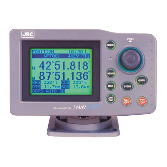
- Page 1 INSTRUCTION MANUAL PUSH MODE MENU GOTO EVENT CONT GPS NAVIGATOR GPS NAVIGATOR NWZ-4551...
-
Page 2: General Information
GPS Navigator J-NAV500 General Information Thank you for purchasing the GPS Navigator J-NAV500. This navigator obtains position data from a GPS/DGPS receiver and can shows all types of marine navigation displays. • Before attempting to operate this unit, read this instruction manual thoroughly to correctly and safely operate this unit in accordance with the warning instructions and operation procedures in this manual. -
Page 3: Before You Begin
GPS Navigator J-NAV500 Before you begin Related symbols In this manual, and on the equipment, there are several labels to call your attention to impor- tant items that, if not handled correctly, could present danger to yourself or property. The labels used and their meaning are described below. -
Page 4: Safety Precautions
GPS Navigator J-NAV500 Safety Precautions WARNING Do not disassemble or modify this unit. Otherwise, a fire, an electrical shock, or a failure may occur. Do not remove or insert the power cable with wet hands. Otherwise, you may suffer from an electrical shock. Do not use voltage other than 12 VDC. - Page 5 GPS Navigator J-NAV500 CAUTION This unit does not automatically assess position informa- tion. It is the user’s responsibility to judge position and navi- gational information. Do not drop this unit into water. When water enters the unit, a failure may occur. When removing the power cord, be sure to remove the power cord terminal correctly.
-
Page 6: Outside View
GPS Navigator J-NAV500 Outside View... -
Page 7: Table Of Contents
GPS Navigator J-NAV500 Contents General Information ................1 Before you Begin ................... 2 Safety Precautions ................3 Outside View ..................5 Definition of Terms ................8 Overview ..................10 Functions ........................ 10 Features ........................11 Equipment supplied ....................11 Structure ......................... 12 Equipment connections .................. - Page 8 GPS Navigator J-NAV500 Adjusting Contrast and Backlighting ..............39 Setting Alarms (Arrival/Anchor/Off-course/DGPS) ..........39 Navigation using direct route (GOTO) ..............41 4.10 Navigation according to route plan ................ 42 4.11 Entering current position as a waypoint [EVENT] ..........43 4.12 Man-Overboard Mode .................... 44 4.13 Position Display Mode/Position Correction/Geodetic System Correction/ Magnetic Compass Correction ................
-
Page 9: Definition Of Terms
GPS Navigator J-NAV500 Definition of Terms GPS satellite GPS stands for “Global Positioning System.” One of several satellites launched by the US Department of Defense to estab- lish a military navigational aid system. DGPS The process of correcting the inaccuracies of GPS position data from GPS satellites by receiving a beacon receiver (via a bea- con station) in a base station whose exact position is known. - Page 10 GPS Navigator J-NAV500 Automatic sequencing mode Function that automatically steps from one waypoint to the next when the arrival perpendicular point has been detected. Manual sequencing mode The unit sounds the arrival alarm and the operator will manually press key to step to next leg in the route plan when it is safe to do so.
-
Page 11: Overview
GPS Navigator J-NAV500 1. Overview 1.1 Functions Attaching an optional GPS/DGPS receiver (GPS 100 or DGPS 200) makes it possible to turn the GPS Navigator J-NAV500 into a GPS/DGPS navigational system. This navigational system uses GPS satel- lites to calculate accurate positions anywhere in the world and under any weather conditions 24 hours a day. -
Page 12: Features
The display can easily be removed or installed by pressing the button on the rear panel. • Support for seven display languages is provided. 1.3 Equipment supplied The table below lists items that are included with your J-NAV500. If an item is missing, contact your JRC dealer for assistance. Item Description Q'ty... -
Page 13: Structure
GPS Navigator J-NAV500 1.4 Structure The outside view of the display unit is shown below. PUSH MODE MENU GOTO EVENT CONT 46.5 46.5 UNIT : mm Figure 1-1 WEIGHT : Less than 0.9kg 1.5 Equipment connections Equipment connections are shown below. GPS/DGPS receiver (optional GPS 100 or DGPS 200) PUSH... -
Page 14: Names And Functions Of Parts
GPS Navigator J-NAV500 2. Names and Functions of Parts 2.1 Operation panel The illustration shows the keys on the operation panel and their functions. PUSH MODE MENU GOTO EVENT CONT Figure 2-1 Name Function Mode • Press this key in mode exept [ MOB ] to select main display mode. •... -
Page 15: Gps Navigator J-Nav
GPS Navigator J-NAV500 Name Function Menu Displays the menus for each display mode. GOTO Use this key to select to destination (see Section 4.9, “Navigation using direct routes (GOTO).” This key function is available in the following display modes: [ POSITION ] , [ NAVIGATION ] , [ CDI ] and [ PLOT ] displays Event Registers the current position (buoy or fishing point) as a waypoint. -
Page 16: Rear Panel
GPS Navigator J-NAV500 2.2 Rear panel GPS/DGPS DC PWR/DATA Figure 2-2 Name Function Release button Press this button to remove the display unit from the bracket. GPS/DGPS Connector for GPS or DGPS receiver (GPS 100 or DGPS 200) DC PWR/DATA Connects supplied power cable. -
Page 17: Installation
GPS Navigator J-NAV500 3. Installation 3.1 Display installation CAUTION Install this unit at least 1 meter away from a magnetic compass. Otherwise, the unit may cause the compass to indicate unreliably. 3.1.1 Choosing the location When choosing a location to mount this unit, please consider the following two criteria for the site. •... -
Page 18: Mounting The Unit
GPS Navigator J-NAV500 3.1.2 Mounting the unit CAUTION When installing this unit on a tabletop, use the designated screws to secure the bracket to a stable wooden surface. Otherwise, the unit could fall and it may cause human injury or property damage. Mount the unit according to the following steps. - Page 19 GPS Navigator J-NAV500 Figure 3-4 As shown below, an optional flush mount kit can be used to wallmount the navigator. For information on mounting, refer to the instruction manual supplied with the kit.
-
Page 20: Cable Connections
GPS Navigator J-NAV500 3.2 Cable connections The connectors on the rear panel are shown in Figure 2-2. CAUTION When the GPS/DGPS receiver has been installed, route the surplus cable from the receiver at a distance of 30 cm or more from this unit to prevent interference from occurring in other communication devices. - Page 21 GPS Navigator J-NAV500 CAUTION Do not connect this unit and the GPS/DGPS receiver to ground when used with a “floating” battery. Should they be connected to ground, large current will flow from this unit or the GPS/DGPS receiver to ground and could cause fire or equipment break- down.
-
Page 22: Ground Connection
GPS Navigator J-NAV500 However, the unit cannot be used on positive ground vessels. Power lead connections 1. Connect the black -12 VDC power cable to the negative pole of the vessel battery. 2. Connect the red +12 VDC power cable to the positive pole of the vessel battery. 3. -
Page 23: Emc Installation & Service Guidelines
3.3 EMC INSTALLATION & SERVICE GUIDELlNES IMPORTANT NOTE All JRC equipment and accessories are designed to the best industry standards for use in the marine environment. Their design and manufacture conforms to the appropriate Electromagnetic Compatibil- ity (EMC) standards, but good installation is required to ensure that performance is not compromised. -
Page 24: Operation
GPS Navigator J-NAV500 4. Operation 4.1 Overview When the setup operations described in Chapter 3 have been completed, turn on the power to start operation. This chapter describes the basic flow of operations. The bold line boxes indicate user opera- tions. -
Page 25: Turning The Unit On/Off
GPS Navigator J-NAV500 4.2 Turning the unit on/off • Press to turn on the unit. • Press simultaneously to turn off the unit. Display changes when the unit is turned on When the unit is turned on, the displays are shown in the order given below: When position fixing is completed, the [POSITION] display is shown. -
Page 26: Selecting Display Language
GPS Navigator J-NAV500 4.3 Selecting display language The display language is set to English at the factory before shipment and reverts to this setting after a master reset. Use the following steps to set it to desired language. One of the following seven language can be set. -
Page 27: Switching Between Main Display Modes
GPS Navigator J-NAV500 4.4 Switching between Main Display Modes This section describes how to switch between the Main display modes, then what display modes can be When the unit is selected from which main display mode. There are seven Main display modes. turned on and GPS position fixing is performed, the [ POSITION ] display mode. - Page 28 GPS Navigator J-NAV500 Display Changes [Main display modes] [[STATUS] display mode] [[ROUTE] display mode] [Select Mode display mode] [Plot scale] [[WAYPOUNT] display mode] display mode 0.5 sec [[PLOT] display mode] [[CDI] display mode] [[NAVIGATION] display mode] 0.5 sec [POSITION] display mode To previous display mode...
-
Page 29: Main Display Modes
GPS Navigator J-NAV500 4.5 Main Display Modes This section describes how to interpret the seven main display modes. • Display modes where waypoints and route plans have already been set are used in the examples. • For information on items shared by each display mode, see Section 4.5.1, “Position display mode.” 4.5.1 POSITION display mode This display mode shows current position and navigation informations. - Page 30 GPS Navigator J-NAV500 Waypoint number Displays the number of currently selected waypoint for destination. Example: WPT 001 WPT: waypoint 001: waypoint number When waypoints are registered through events, a “D” or “G” is appended to the waypoint number to indicate the position fixing of GPS or DGPS, respectively. Waypoint name Displays the name registered for a waypoint.
- Page 31 GPS Navigator J-NAV500 A “t” after the figure for BRG, COG and CMG indicates true bearing, while “m” indicates that magnetic compass correction has been made.) Position fix status This position is displayed GPS position fix status. When a problem has occurred in position fixing, HDOP, NO FIX or DGPS alarm is displayed. For information on alarms, see Appendix A, “Message list.”...
- Page 32 GPS Navigator J-NAV500 The operation of each alarm is described in the figures shown below. ARV (arrival alarm) ANC (anchor alarm) The alarm goes off when the ship comes inside a The alarm goes off when the ship goes beyond a set distance of a waypoint.
-
Page 33: Navigation Display Mode
GPS Navigator J-NAV500 4.5.2 NAVIGATION display mode This display mode shows the following navigation information. The type of data displayed in this display mode can be selected in the menus. Navigation information [NAVIGATION] display mode is the type of information indicated in , “Navigation information”... -
Page 34: Plot Display Mode And Setting The Plot Scale
GPS Navigator J-NAV500 Course over ground (unit: ) “t” indicates true bearing and “m” indicates magnetic compass corrected value. Displays the average speed (speed over ground) in kt (knots), mh, kh CDI Range Displays 0.1 (default), 0.3, 0.5 nm depending on setting. (See Section 4.15, “Setting CDI range and Display Time Format.”) 4.5.4 PLOT display mode and setting the plot scale PLOT display mode... -
Page 35: Waypoint Display Mode
GPS Navigator J-NAV500 4.5.5 WAYPOINT display mode This display mode shows a list of registered waypoints. Waypoint name Waypoint number Date (date entered waypoint) D: registered DGPS position Waypoint position G: registered GPS position No indication: registration other than EVENT Distance to current position Bearing to current position Turn... -
Page 36: Status/Sf Display Mode
GPS Navigator J-NAV500 4.5.7 STATUS display mode The [STATUS] display mode shows all relevant satellite data. Satellite number Azimuth angle Elevation angle Receiving level HDOP value Beacon status Antenna height Date Satellite number Displays numbers for the receiving satellites (8 of 01 to 32) Azimuth angle Displays the azimuth angle: N, NE, E, SE, S, SW, W, NW Elevation angle... - Page 37 GPS Navigator J-NAV500 Tip HDOP level A standard for assessing accuracy of position fixing. HDOP is based on the shape formed by the positions of satellites and the receiver; a good shape yields a low HDOP level and an accurate position fix value.
-
Page 38: Basic Menu Selection Operations
GPS Navigator J-NAV500 4.6 Basic menu selection operations The use of the has already been described in sections 4.3, “Selecting display language” and 4.4, “Switching between Main Display Modes.” This section will describe menu selections in detail. can be turned and pressed to select and confirm selected menus; familiarize yourself with it and you will be able to speedily select menus and confirm selections. - Page 39 GPS Navigator J-NAV500 Setting position display type (1) Turn in the [POSITION MEN] display mode to select the [L/L OR TD] menu. [L/L OR TD] is highlighted and currently selected item [L/L] is displayed. (2) Press to confirm [L/L OR TD] selection. All selected items are displayed and currently selected item [L/L] is highlighted.
-
Page 40: Adjusting Contrast And Backlighting
GPS Navigator J-NAV500 4.7 Adjusting Contrast and Backlighting This function adjusts contrast and backlighting in all displays. (1) Press This action displays the display for changing the contrast and back- lighting. (2) Turn to select the desired contrast. Range of contrast selection: 00 to 15 (default value: 07 ) (3) Press . - Page 41 GPS Navigator J-NAV500 Setting 1) Arrival alarm The arrival alarm can be set to alert you when you are within a specified distance from your Alarm range waypoint. The arrival alarm can be set within a Waypoint Position range of 0.00 to 9.99 nm . •...
-
Page 42: Navigation Using Direct Route (Goto)
GPS Navigator J-NAV500 4.9 Navigation using direct route [GOTO] A registered waypoint number can be selected as a direct destination by pressing and entering a waypoint number. The function is available in the following four main display modes: • [POSITION], [NAVIGATION], [CDI] and [PLOT] display modes The procedure to make direct route selection is the same in four display modes. -
Page 43: Navigation According To Route Plan
GPS Navigator J-NAV500 4.10 Navigation according to route plans Select the number of the route plan you wish to follow. When the number of the route plan has been selected, perform the settings in the displays that appear. For information on route plans, see Section 4.18, "Setting Route Plans." Display example [Route Plan] display mode (1) Press... -
Page 44: Entering Current Position As A Waypoint [Event]
GPS Navigator J-NAV500 The alarm setting made in Section, “4.8 Setting Alarms (Arrival/Anchor/Off-course/DGPS)” are replaced by the arrival alarm distance made here. The route plan numbers entered here are highlighted in the [Route] display mode. An automatic step cannot be performed by selecting [Auto] in step (5) when [0.00] is set in [Set Arrival Distance]. To make an step, press , like in manual step, to step the waypoint. -
Page 45: Man-Overboard Mode
GPS Navigator J-NAV500 4.12 Man-Overboard Mode The MOB function (Man-overboard) is useful if something or someone falls overboard. Press and the navigator shows a graphic display of the position allowing you to steer back to the position where the event occurred. function is available in all display modes. - Page 46 GPS Navigator J-NAV500 Display operations • Press in the [POSITION] display mode. • To return to the [POSITION] display mode, press Display example [Latitude, Longitude display] [Time Difference Display] Setting (1) Display format The [POSITION] display mode can be set to one of the following display formats. L/L : latitude, longitude display (default) L/L OR TD TD : Time Difference display...
-
Page 47: Setting Navigation Display Modes And Units
GPS Navigator J-NAV500 The correction value may differ with the sea area. If so, correct as required. 4.14 Setting Navigation Display Modes and Units Display operations • Press in the [NAVIGATION] display mode. • To return to the [NAVIGATION] display mode, press Setting (1) The navigation information can be displayed in one of the following type. -
Page 48: Setting Cdi Range And Display Time Format
GPS Navigator J-NAV500 4.15 Setting CDI range and Display Time Format Display operations • Press in the [CDI] display mode. • To return to the [CDI] display mode, press Setting (1) CDI range The CDI range can be set as follows: CDI RANGE: 0.1 (default), 0.3, 0.5 nm (2) Display time format Time can be displayed according to the following formats:... -
Page 49: Entering Waypoints
GPS Navigator J-NAV500 (4) Waypoint symbol It is possible to display the first letter of the waypoint name as a waypoint mark on the display. This display function can be turned on and off. on (default) /off MARKS 4.17 Entering Waypoints Waypoints can be entered in one of the following four ways: •... -
Page 50: Editing Waypoint Lists
GPS Navigator J-NAV500 WAYPOINT display mode and waypoint menu • The [WAYPOINT] display mode is used for displaying and editing waypoints. (See Section 4.17.1.) • The following settings can be made in the [WAYPOINT MENU] displayed by pressing in the [WAYPOINT] display mode. •... -
Page 51: Storing Waypoints
GPS Navigator J-NAV500 4.17.2 Storing waypoints Storing by LAT/LON (When the [L/L] is selected.) Use the following procedure to enter waypoint by latitude and longitude. in the [WAYPOINT] display mode. This displays the [WAYPOINT MENU] . (1) Press (2) Press to select [ENTER NEW WPT BY L/L] and press . - Page 52 GPS Navigator J-NAV500 Storing by TDs (TD1, TD2) (When the [TD] is selected.) Use the following procedure to enter the position of a waypoint using time differences. (1) Press in the [WAYPOINT] display mode. This displays the [WAYPOINT MENU] . (2) Turn to select [ENTER NEW WPT BY TD] and press Display example...
-
Page 53: Erasing, Copying And Measuring Waypoints
GPS Navigator J-NAV500 4.17.3 Erasing, copying and measuring waypoints The following three functions are described below. • Erasing waypoints: Erasing waypoints no longer required. • Copying waypoints: Copies registered waypoints. For information on how to edit copied waypoints, see Section 4.17.1, “Editing Waypoints.” •... - Page 54 GPS Navigator J-NAV500 Copying waypoints (1) Press in the [WAYPOINT] display mode. (2) Turn to select [ERASE/COPY/MEASURE] and press (3) Turn to select [COPY WAYPOINT] and press (4) Enter the number of the waypoint to be copied in the [FROM] field. (5) Enter the number of the destination of the waypoint in the [TO] field.
-
Page 55: Sorting Waypoint List
GPS Navigator J-NAV500 4.17.4 Sorting waypoint list The waypoint list can be sorted either in number order or in the alphabetic order of the waypoint names. In alphabetic order, characters are sorted in the following order: symbols, alphabetic characters, numbers and spaces. -
Page 56: Making A Route Plan
GPS Navigator J-NAV500 4.18.1 Making route plan The following displays are used for making route plans. Display examples [Route Plan] display mode in the [ROUTE] display mode. This displays the [ROUTE MENU] . (1) Press (2) Turn to select [MAKE ROUTE] and press This displays the [ROUTE MENU] . -
Page 57: Editing Route Plan
GPS Navigator J-NAV500 4.18.2 Editing route plan Routes can be inserted to or deleted from registered route plans as you wish. in the [Edit Route] display mode as shown below. • : Key for inserting waypoint numbers • : Key for deleting waypoint numbers Display examples [ROUTE] display mode [Delete]... -
Page 58: Erasing Route Plans
GPS Navigator J-NAV500 (4) This example will show how to delete waypoint 003 from LEG 002 and to insert a new waypoint 005. • Deleting waypoint #003 As shown above, turn to select LEG002 and press to confirm LEG002. Press to delete #003 of LEG002. -
Page 59: Setting Gps Information
GPS Navigator J-NAV500 4.19 Setting GPS information For information on entry operations given below, see Section 4.6, “Basic menu selection operations.” Display examples [STATUS] Display Mode [STATUS/SF Menu] 4.19.1 Setting position fix mode and averaging for GPS Setting position fix mode (1) Press in the [STATUS] mode display. -
Page 60: Initializing Gps/Dgps Receiver
GPS Navigator J-NAV500 4.19.2 Initializing GPS/DGPS receiver The following benefits are provided by initializing GPS/DGPS receiver. • Position fixing the first time the navigator is used or after a master reset takes about 20 minutes. Initializing reduces this time. Display example [STATUS/SF Menu] [ESTIMATED L/L] [ESTIMATED L/L]... -
Page 61: Td Initializing
GPS Navigator J-NAV500 4.19.3 TD initializing The first time the navigator is used or after a master reset, the position display format is set to latitude and longitude (L/L) and the name of the menu in the [STATUS/SF MENU] is not [ESTIMATED TD] but [ESTIMATED L/L] . -
Page 62: Setting Dgps Beacon
GPS Navigator J-NAV500 4.19.4 Setting DGPS beacon The frequency and Baud rate of the received beacon station can be set. Display example [STATUS/SF Menu] display mode [STATUS/SF MENU DGPS] display mode (1) Press in the [STATUS] display mode. This action displays the [STATUS/SF MENU] . (2) Turn to select [DGPS Beacon] and press When a DGPS beacon receiver or DGPS receiver (DGPS200) is not connected, the message [No... -
Page 63: Setting Data Output And Transmit Memory Data
GPS Navigator J-NAV500 4.20 Setting Data Output and transmit memory data CAUTION When a PC (Personal Computer) is connected to this unit, the output level must be set to TTL when data is input from the PC since an RS-422 setting could damage the PC and this unit. - Page 64 GPS Navigator J-NAV500 Output level setting (1) Press in the [STATUS] display mode. This action displays the [STATUS/SF MENU] . (2) Turn to select [SPECIAL FUNCTION] and press The [SF MENU] display mode appears. (3) Turn to select [DATA OUTPUT] and press The [SF MENU DATA OUTPUT] display mode appears.
-
Page 65: Displaying The Simulator Mode
GPS Navigator J-NAV500 (5) Memory data input Waypoint and route plan data can be downloaded separately from external equipment such as a During the download the message [DOWNLOADING] is displayed. When the message ÒDOWNLOADINGÓ is displayed, inputs are received from external equipment. The time required for the transfer depends on the amount of data transferred. -
Page 66: Performing Master Reset
GPS Navigator J-NAV500 4.22 Performing Master Reset • A master reset clears registered date. Use this function with care. • When resetting the navigator, perform Initializing GPS/DGPS receiver as described in section 4.19.2 when correcting for local time. There are a soft and hard reset functions. A soft reset clears all data except waypoint and route plan data. -
Page 67: Maintenance And Inspection
The life of the battery is more than five years. However, to ensure proper operation of the receiver, replace it before it has been completely depleted. Let JRC, our agents or dealers replace the battery for you when it is time to replace it. Lithium battery... -
Page 68: After-Sales Service
To prevent this, periodic maintenance is required in addition to regular inspections. For information on maintenance, contact your dealer. Note that maintenance is charged for. Inquiries should be directed to JRC. Addresses and telephone numbers are listed on the back cover of this manual. -
Page 69: Disposal
GPS Navigator J-NAV500 7. Disposal WARNING Before you dispose of a lithium battery, place a piece of adhesive tape across the plus an minus terminals to prevent electric shorts that could result in fire, explosions or other hazards. 7.1 Disposal of Navigator Observe all national laws and regulations when you dispose of the navigator. -
Page 70: Specifications
GPS Navigator J-NAV500 8. Specifications Display Blue (neutral mode) STN type Dot Materix: 128 x 100 dots Size: 79 mm W x 61 mm H LCD contrast adjustment Automatic adjustment by using temperature sensor and manual adjust Backlighting EL panel for LCD, LED for key switches Brightness adjustment 2 step keyboard setting, high/low Key switches... - Page 71 GPS Navigator J-NAV500 Memory backup Internal lithium battery Power supply Input voltage: 12 VDC (10.8 to 16.0 VDC) Power consumption: 6 W or less (with GPS/DGPS receiver) OWeight less than 0.9kg. Operating environment Ð15 C to +55 C Storage environment Ð40 C to +80 C Operating humidity +40 C, 93%...
-
Page 72: Appendices
Appendix A Message list Error messages Message Description RAM NG Display RAM failure. Contact JRC sales department or local branch. ROM NG Display ROM failure. Contact JRC sales department or local branch. RCV NG GPS/DGPS receiver is not connected or is malfunctioning. - Page 73 GPS Navigator J-NAV500 Operation messages Message Description EVENT FULL Too many events (waypoints) registered. This message is displayed when an attempt is made registered a new event. Delete old data before making new registration. WPT FULL Too many waypoints registered. Delete old data before making new registra- tion.
-
Page 74: Appendix B Geodetic System Table
GPS Navigator J-NAV500 Appendix B Geodetic System Table The navigator displays the names of geodetic system 1 to 9, but only the numbers are given for datums 11 and beyond. Tables 1 and 2 list all the 46 geodetic system that are used. Table 1... - Page 75 GPS Navigator J-NAV500 Geodetic system 11 to 47 Table 2...
-
Page 76: Appendix Cnmea0183 Output Sentence And Data Format
GPS Navigator J-NAV500 Appendix C NMEA0183 output sentence and data format Output sentences RMC : Recommended Minimum Specific GPS/Transit Data. RMB : Recommended Minimum Navigation Information. APB : Autopilot Sentence “B”. BWC : Bearing & Distance to Waypoint. GLL : Geographic position - Latitude/Longitude, GGA : Global Position System Fix data. - Page 77 GPS Navigator J-NAV500 RMB sentences $GPRMB,A,x.xx,a,cccc,cccc,llll.ll,a,yyyyy.yy,a,xxx.x,xxx,uxx.x,A*hh<CR><LF> 12 13 14 Data status A: valid V: invalid Cross track error (NM) Direction to steer L = left, R = right Origin waypoint ID Destination waypoint ID 6, 7 Destination waypoint latitude, N/S 8, 9 Destination waypoint longitude, E/W Range to destination (NM)
- Page 78 GPS Navigator J-NAV500 GLL sentences $GPGLL,ddmm.mm,a,dddmm.mm,a<CR><LF> 1, 2 Latitude (Degree, Minute), N/S 3, 4 Longitude (Degree, Minute), E/W GGA sentences $GPGGA,hhmmss,ddmm.mmm,a,dddmm.mmm,a,x,x,xx,uxxxx,M,,M,,<CR><LF> 5 6 7 8 UTC of position (Hour, Minute, Second) 2, 3 Latitude (Degree, Minute), N/S 4, 5 Longitude (Degree, Minute), E/W GPS quality indicator 0 = GPS No Fix, 1= GPS Fix, 2 = Differential GPS Fix Number of statellites in use for position fix Horizontal dilution of precision (HDOP)
- Page 79 GPS Navigator J-NAV500 RMB sentences $GPRMB,A,x.xx,a,cccc,cccc,llll.ll,a,yyyyy.yy,a,xxx.x,xxx,uxx.x,A*hh<CR><LF> 13 14 Data status A: valid V: invalid Cross track error (NM) Direction to steer L = left, R = right Origin waypoint ID Destination waypoint ID 6, 7 Destination waypoint latitude, N/S 8, 9 Destination waypoint latitude, E/W Range to destination (NM) Bearing to destination, degree true...
- Page 80 GPS Navigator J-NAV500 GLL sentences $GPGLL,ddmm.mmm,a,dddmm.mmm,a,hhmmss,A*hh<CR><LF> 1, 2 Latitude ((Degree, Minute), N/S 3, 4 Longitude (Degree, Minute), E/W UTC of position (Hour, minute, Second) Data status A: valid, V: invalid Checksum GGA sentences $GPGGA,hhmmss,ddmm.mmm,a,dddmm.mmm,a,x,x,xx,uxxxx,M,,M,,*hh<CR><LF> 5 6 7 8 UTC of position (Hour, Minute, Second) 2, 3 Latitude ((Degree, Minute), N/S 4, 5...
-
Page 81: Appendix D Waypoint/Route Plan Data In/Output
GPS Navigator J-NAV500 Appendix D Waypoint/Route Plan Data In/Output Serial format Baud rate 4800 bps Data bits 8 bits Parity None Start bit 1 bit Stop bit 1 bit Waypoint data I/O $PJWPL,llll.lll,a,yyyyy.yyy,a,ccc*hh 1, 2 Latitude ( , minute) 3, 4 Longitude ( , minute) Waypoint number Checksum... -
Page 82: Appendix E Waypoint List
GPS Navigator J-NAV500 Appendix E Waypoint List Waypoint no. Waypoint name Remarks... - Page 83 GPS Navigator J-NAV500 Waypoint no. Waypoint name Remarks...
- Page 85 For further information contact : HEAD OFFICE & Akasaka Twin Tower(MAIN), SALES DEPT. 17-22, Akasaka 2-chome, Minato-ku, Tokyo 107-8432 JAPAN : +81-3-3584-8711 Phone : +81-3-3584-8715 : 0242-5420 JRCTOK J Telex MAIN PLANT 1-1, Shimorenjaku 5-chome, Mitaka-shi, Tokyo 181-8510 JAPAN Phone : +81-422-45-9111 : +81-422-45-9110 Telex...
Need help?
Do you have a question about the J-NAV 500 and is the answer not in the manual?
Questions and answers