Intel SR1670HV - Server System - 0 MB RAM Service Manual
Server system
Hide thumbs
Also See for SR1670HV - Server System - 0 MB RAM:
- Technical product specification (92 pages)

Related Manuals for Intel SR1670HV - Server System - 0 MB RAM


Summary of Contents for Intel SR1670HV - Server System - 0 MB RAM
- Page 1 ® Intel Server System SR1670HV Service Guide Intel Part Number: E74138-004 ® A Guide for Technically Qualified Assemblers of Intel Identified Subassemblies/Products...
- Page 2 Intel’s own chassis are designed and tested to meet the intended thermal requirements of these components when the fully integrated system is used together. It is the responsibility of the system integrator that chooses not to use Intel developed server building blocks to consult vendor datasheets and operating parameters to determine the amount of airflow required for their specific application and environmental conditions.
- Page 3 Disclaimer <This page is intentionally left blank.> ® Intel Server System SR1670HV Service Guide...
-
Page 4: About This Manual
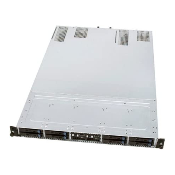
Manual Organization ® Chapter 1 provides a brief overview of the Intel Server System SR1670HV. In this chapter, you will find a list of the system features, product photos, and product diagrams to help you identify components and their locations. -
Page 5: Additional Information And Software
Preface Additional Information and Software Documentation and software for this server product are available on the Intel Resource CD that shipped with your Intel server product. Software updates and additional information can be obtained at the following Intel web site: http://support.intel.com/support/motherboards/server/SR1670HV/... -
Page 6: Table Of Contents
Clear RTC RAM (CLRTC1) ................35 5.1.2 VGA Controller Setting (3-pin VGA_SW1) ............ 36 5.1.3 DDR3 Voltage Control Setting (4-pin LVDDR3_SEL1, LVDDR3_SEL2) ..36 5.1.4 LAN Controller Setting (3-poin LAN_SW1, LAN_SW2) ......... 37 ® Intel Server System SR1670HV Service Guide... - Page 7 Contents ® 5.1.5 Intel ICH10R SATA Port SW RAID Setting (3-pin RAID_SEL1) ....37 5.1.6 Force BIOS Recovery Setting (3-pin RECOVERY1)........38 Server Board Connectors..................... 39 5.2.1 Serial ATA Connectors (7-pin SATA1, SATA2, SATA3, SATA4) ....39 5.2.2 Internal USB Connectors (A-Type USB4; 5x1 pin USB3) ......39 5.2.3...
- Page 8 Contents 8.5.5 Contact Information ..................106 ® 9. Intel Server Issue Report Form..............107 Getting Help ..................112 10.1 Warranty Information....................112 Safety Information ................113 Server Safety Information ....................114 Safety Warnings & Cautions ....................114 Intended Application Uses ....................115 Site Selection ........................
- Page 9 PRECAUCIÓN ..................... 137 服务器安全信息 ........................138 安全警告与注意事项......................138 预期应用使用........................138 场地选择..........................139 设备操作规范........................139 电源与电气警告 ........................139 系统使用警告........................140 机架固定件警告 ........................141 静电放电 (ESD) ........................141 注意事项 ................... 141 其他危险..........................141 注意事项 ....................... 142 ® Intel Server System SR1670HV Service Guide...
- Page 10 Figure 44. Pushing the New PSU Into the Chassis ..............28 Figure 45. Disconnecting System Fan Cable................29 Figure 46. Lifting System Fan ..................... 29 Figure 47. Inserting Fan Into the Fan Cage ................29 ® Intel Server System SR1670HV Service Guide...
- Page 11 Figure 61. DDR3 Voltage Control Setting ................... 37 Figure 62. LAN Controller Setting ....................37 ® Figure 63. Intel ICH10R SATA Port SW RAID Setting .............. 38 Figure 64. Force BIOS Recovery Setting..................38 Figure 65. SATA Connectors ...................... 39 Figure 66.
- Page 12 Figure 142. Specifying an Additional Device ................95 Figure 143. Insert RAID Driver Disk Screen ................95 Figure 144. Intel ICH8R/ICH9R/ICH10R/DO SATA RAID Controller Item........96 Figure 145. Installing Red Hat* Enterprise.................. 96 Figure 146. Driver Disk Y/N Screen.................... 97 Figure 147.
- Page 13 Figure 160. Intel Network Connections Software Window ............102 Figure 161. Intel(R) Network Connections—InstallShield Wizard..........102 Figure 162. License Agreement Terms..................102 Figure 163. Intel(R) PROSet for Windows Device Manager Option ......... 103 Figure 164. Beginning the Installation..................103 Figure 165. Drivers Menu ......................104 Figure 166.
- Page 14 Table 6. HDD LED Status Definitions ................... 7 Table 7. Maximum Memory Allocation Using RDIMMs............... 16 Table 8. Supported RDIMM Configurations ................17 Table 9. Supported UDIMM Configurations ................17 Table 10. Memory Population Table ................... 18 ® Intel Server System SR1670HV Service Guide...
- Page 15 List of Tables <This page intentionally left blank.> ® Intel Server System SR1670HV Service Guide...
-
Page 16: Product Introduction
Product Introduction 1. Product Introduction ® This chapter briefly describes the main features of the Intel Server System SR1670HV. 1.1 System Package Contents Check your system package for the following items. Table 1. System Package Contents List Model Name ®... -
Page 17: Front Panel Features
Dual 770-W cold swap Power Supply modules. (non-redundant) ® ® Networking 4 x 10/100/1000 Ethernet ports provided by Intel 82574L PHYs with Intel Acceleration Technology (Two LAN ports per server node) Server Management On-board ASPEED AST2050 with integrated Baseboard Management Controller 2 x BMC Management Modules with IPMI 2.0 support (One per server node) -
Page 18: Rear Panel Features
Add-in card slot covers for each installed server node. External I/O ports for each installed server node. Figure 2. System Features – Back Panel 1.5 Internal Features The following figure shows the internal features of the server system. ® Intel Server System SR1670HV Service Guide... -
Page 19: Figure 3. System Component Identification
4 x System 4 x System Fans Fans Node 2 Node 1 Hard Disk Drive Bay Module Figure 3. System Component Identification The following figure identifies connectors and major components of each server node. ® Intel Server System SR1670HV Service Guide... -
Page 20: Figure 4. Server Node Connectors And Components
Product Introduction Figure 4. Server Node Connectors and Components ® Intel Server System SR1670HV Service Guide... -
Page 21: System Led Information
Location switch is pressed (Press the location switch again to turn off). BMC reset in progress when re-plug Power cord LAN LEDs No LAN connection Blinking LAN is transmitting or receiving data. LAN connection is present. ® Intel Server System SR1670HV Service Guide... -
Page 22: Lan Ports 1 And 2 Leds
NOTE: The bundled system cables are pre-connected before shipment. You do not need to disconnect these cables unless you must remove pre-installed components for servicing or to install additional devices. Refer to Chapter 4, “System Service” for detailed information on the connections. ® Intel Server System SR1670HV Service Guide... -
Page 23: Pre-Connected System Cables
4. USB connector (from server board to front control panel) 5. Front Control Panel connector (from server board to front control panel) 6. SATA connectors (from server board to backplane) 7. Auxiliary Panel connector (from server board to front control panel) ® Intel Server System SR1670HV Service Guide... -
Page 24: Hardware Setup
2.2 Central Processing Unit (CPU) Each installed server node provides two surface mount LGA 1366 CPU sockets designed ® ® for the Intel Xeon Processor 5500 series and 5600 series. CAUTIONS Upon purchase of the server board, ensure the PnP caps are installed on each processor socket and the socket contacts are not bent. -
Page 25: Installing The Processor
2. Press the load lever with your thumb (A), then move it to the left (B) until it is released from the retention tab. CAUTION To prevent damage to the socket pins, do not remove the PnP cap unless you are installing a processor. ® Intel Server System SR1670HV Service Guide... -
Page 26: Figure 12. Retention Tab And Load Lever
CAUTION The processor fits in only one correct orientation. DO NOT force the processor into the socket to prevent bending the connectors on the socket and damaging the processor! ® Intel Server System SR1670HV Service Guide... -
Page 27: Figure 15. Cpu Notch And Alignment Key
To prevent contaminating the paste, DO NOT spread the paste with your finger directly. 8. Close the load plate (A), and then push the load lever (B) until it snaps into the retention tab. ® Intel Server System SR1670HV Service Guide... -
Page 28: Installing The Processor Heatsink
Engage screws at locations 3 and 4 by giving each screw two rotations and then stop. 5. Repeat steps 4a through 4c by giving each screw two rotations each time until all screws are lightly tightened up to a maximum of 8 inch-pounds torque. ® Intel Server System SR1670HV Service Guide... -
Page 29: Removing The Processor Heatsink
2. Twist the heatsink slightly to break the seal between the heatsink and the processor. 3. Lift the heatsink from the processor. If it does not pull up easily, twist the heatsink again. Do not force the heatsink from the processor. Doing so could damage the processor. ® Intel Server System SR1670HV Service Guide... -
Page 30: System Memory
On a given server node, DIMM sockets DIMM_D1 through DIMM_F2 are not enabled in single processor configurations. The following figure illustrates the location of the DDR3 DIMM sockets. ® Intel Server System SR1670HV Service Guide... -
Page 31: Memory Support
96 GB 800 MHz only (12x 8GB DIMMs) ® NOTE: Due to thermal requirements needed to support Quad Rank x4 DDR3 DIMMs, the Intel Server System SR1670HV does not support this memory type. ® Intel Server System SR1670HV Service Guide... -
Page 32: Table 8. Supported Rdimm Configurations
No x4 SDDC support with UDIMM with ECC; however, x8 SDDC is supported in lock step mode with x8 UDIMMs with ECC. NOTE: Although non-ECC memory can be used in this server system, Intel does not plan to validate them and strongly discourages their use in a working server environment. -
Page 33: Installing A Dimm
1. Unlock a DIMM socket by pressing the retaining clips outward. 2. Align a DIMM on the socket so the notch on the DIMM matches the break on the socket. ® Intel Server System SR1670HV Service Guide... -
Page 34: Removing A Dimm
Figure 23. DIMM Notch NOTE: Support the DIMM lightly with your fingers when pressing the retaining clips. The DIMM might get damaged when it flips out with extra force. 2. Remove the DIMM from the socket. ® Intel Server System SR1670HV Service Guide... -
Page 35: Installing A Pci Express* Add-In Card To The Riser Bracket
3. Install a PCI Express* add-in card to the bracket as shown, and then secure the card with a screw. Figure 26. PCI Express* x 16 Card 4. Press the riser card bracket until the golden connectors completely fit the slot and the bracket aligns with the rear panel. ® Intel Server System SR1670HV Service Guide... -
Page 36: Figure 27. Pressing Rising Card Bracket For Golden Connectors To Fit
Hardware Setup Figure 27. Pressing Rising Card Bracket for Golden Connectors to Fit 5. If applicable, connect the cable(s) to the card. ® Intel Server System SR1670HV Service Guide... -
Page 37: Installing The Bmc Management Module
BMC controller on the BMC Management Module. Once the BMC reset is complete, the System ID LED will turn off, and the power button functionality will be re- enabled. ® Intel Server System SR1670HV Service Guide... -
Page 38: Hard Disk Drives
4. Carefully insert the drive assembly into a drive bay until contact is made with the backplane. 5. Push the tray lever in until it clicks and secures the drive tray in place. The drive tray is correctly placed when its front edge aligns with the bay edge. ® Intel Server System SR1670HV Service Guide... -
Page 39: Figure 34. Pushing The Tray Lever
Hardware Setup Figure 34. Pushing the Tray Lever 6. Repeat Steps 1 through 5 to add additional hard drives to the system. ® Intel Server System SR1670HV Service Guide... -
Page 40: Installing The Rackmount Rail Kit
1. Attach the front end of the server rail to the side of the chassis, matching each of the three hooks to the holes on the rail, and then slide the rail towards the front panel until it locks into place. ® Intel Server System SR1670HV Service Guide... -
Page 41: Attaching The Rack Rails
5. Measure the rack rail when assembled to ensure it fits the rack. 6. Position the rack rail to the 1U space on the rack. Ensure the front end of the rack rail goes to the front of the rack space. ® Intel Server System SR1670HV Service Guide... -
Page 42: Rackmounting The Server
1. Align the server rails with the rack rails, and then push the server all the way to the depth of the rack. 2. Drive a screw on the mounting ear to secure the server in place. Figure 41. Mounting Ear ® Intel Server System SR1670HV Service Guide... -
Page 43: System Service
Figure 43. Pulling Out the Failed PSU 4. Firmly push the new PSU into the chassis until the latch locks to the server chassis. Figure 44. Pushing the New PSU Into the Chassis ® Intel Server System SR1670HV Service Guide... -
Page 44: Replacing System Fans
1. Insert the fan into the fan cage. The airflow directional arrow on the fan side should point towards the system rear panel. Figure 47. Inserting Fan Into the Fan Cage 2. Connect the system fan cable to the fan connector on the server board. ® Intel Server System SR1670HV Service Guide... -
Page 45: Sata/Sas Backplane Replacement
Figure 49. Screws On Hard Disk Drive Bay Module 4. Slide the HDD bay module forward approximately ½ inch (1.27cm) and lift front edge of module from alignment guide slots. Figure 50. Sliding the Hard Disk Drive Bay Module ® Intel Server System SR1670HV Service Guide... -
Page 46: Figure 51. Connected Cables And Backplane Expose
Make sure you reconnect each cable pair to the correct backplane connectors. 11. Unpack the replacement backplane. 12. Reconnect the front panel cable pairs to the correct connectors on the backplane. ® Intel Server System SR1670HV Service Guide... -
Page 47: Figure 53. Cable Bundles In The Hard Disk Drive Bay Module
Figure 54. SATA Cable Connection Order 16. Carefully reposition the hard drive bay module on to the server chassis, such that the module falls within alignment slots on each side of the chassis. ® Intel Server System SR1670HV Service Guide... -
Page 48: Front Control Panel Replacement
2. Remove the single screw holding the Control Panel Module in place. Figure 56. Control Panel Module Screw 3. Carefully pull back the Control Panel module until the cables are fully exposed and accessible. ® Intel Server System SR1670HV Service Guide... -
Page 49: Figure 57
10. Reattach each cable pair to the appropriate Control Panel board. 11. Carefully slide the Control Panel Module back into the module bay until the screw holes are in alignment. 12. Using the single screw, fasten the Control Panel module to the chassis. ® Intel Server System SR1670HV Service Guide... -
Page 50: Jumpers, Connectors, And Leds
NOTE: If the steps above do not help, remove the onboard battery and move the jumper again to clear the CMOS RTC RAM data. After the CMOS clearance, reinstall the battery. Figure 59. Clear RTC RAM ® Intel Server System SR1670HV Service Guide... -
Page 51: Vga Controller Setting (3-Pin Vga_Sw1)
LV (low voltage) DDR3 DIMMs on this server board is intended for future use only, and will only be supported after Intel has validated their functionality. This document will be updated with full usage information once validation is complete and tested LV DDR3 DIMMs are added to the Tested Memory List for this server board. -
Page 52: Lan Controller Setting (3-Poin Lan_Sw1, Lan_Sw2)
This jumper allows you to select the Serial ATA RAID configuration utility to use when you create disk arrays. Place the jumper caps on pins 1-2 to select the LSI* SATA Software ® RAID utility (default); otherwise, place the jumper caps on pins 2-3 to use the Intel Matrix Storage Manager (IMSM) ®... -
Page 53: Force Bios Recovery Setting (3-Pin Recovery1)
Jumpers, Connectors, and LEDs ® Figure 63. Intel ICH10R SATA Port SW RAID Setting 5.1.6 Force BIOS Recovery Setting (3-pin RECOVERY1) This jumper allows you to quickly update or recover the BIOS settings when it becomes corrupted. To update the BIOS: 1. -
Page 54: Server Board Connectors
Serial ATA Connectors (7-pin SATA1, SATA2, SATA3, SATA4) ® Supported by the Intel ICH10R chipset, these connectors are for the Serial ATA signal cables for Serial ATA hard disk drives that allow up to 3 Gb/s of data transfer rate. -
Page 55: System Fan Connectors
Figure 67. Front Fan Connectors 5.2.4 Serial General Purpose Input/Output Connector (6-1 pin SGPIO1) ® This connector is used for the SGPIO peripherals for the LSI* Software RAID and Intel Matrix RAID SATA LED. Figure 68. Serial General Purpose I/O Connector ® Intel... -
Page 56: Bmc Management Module Header (Bmc_Fw1)
These connectors allow you to connect SMBus (System Management Bus) to the power supply unit to read PSU information. Devices communicate with a SMBus host and/or other SMBus devices using the SMBus interface. Figure 70. Power Supply SMBus Connectors ® Intel Server System SR1670HV Service Guide... -
Page 57: Main Power Connectors (20-Pin Pwr1, 20-Pin Pwr2)
This connector has the following pin-out and board location: Figure 72. Peripheral Power Connector (4-pin PWR3) 5.2.9 System Panel Connector (20-pin PANEL1) This connector supports several chassis-mounted functions. ® Intel Server System SR1670HV Service Guide... -
Page 58: Figure 73. System Panel Connector
ON turns the system OFF. 5.2.9.6 Reset button (2-pin RESET) This 2-pin connector is for the chassis-mounted reset button for system reboot without turning off the system power. ® Intel Server System SR1670HV Service Guide... -
Page 59: Auxiliary Panel Connector (20-Pin Aux_Panel1)
LED cables to this 2-pin connector. The LEDs will light up when the Locator button is pressed. 5.2.10.5 System ID Button/Switch (2-pin LOCATORBTN) These leads are for the locator button on the front panel. This button queries the state of the system locator. ® Intel Server System SR1670HV Service Guide... -
Page 60: Internal Leds
The following illustration shows the location of the onboard LED. Figure 75. Standby Power LED 5.3.2 CPU Warning LED (ERR_CPU1, ERR_CPU2) The CPU warning LEDs light up to indicate an impending failure of the corresponding CPU. Figure 76. ERR CPU LED ® Intel Server System SR1670HV Service Guide... -
Page 61: System Identification Led
BMC LED (BMC_LED1) The server board includes a BMC LED. With the BMC Management Module installed, this LEDs blinks once per second to indicate the BMC is operating. Figure 78. BMC LED (BMC_LED1) ® Intel Server System SR1670HV Service Guide... -
Page 62: Bios Updates And Configuration
README.TXT – Release notes for the BIOS Update describing changes. NOTE: Prior to updating the System BIOS, Intel recommends reading the Release Notes to fully understand the changes made to the new release and determine how they may affect your system after the update in completed. -
Page 63: Bios Recovery Process
6.2 BIOS Recovery Process In the unlikely event your system BIOS gets corrupted, you should complete the following BIOS recovery process: 1. Download the latest BIOS or System Update Package from the following Intel Web Site http://support.intel.com/support/motherboards/server/SR1670HV/ 2. Extract all the files from the update package to the root directory of a DOS bootable USB Flash Drive. -
Page 64: Bios Setup Utility
BIOS Setup Utility Navigation BIOS Setup Utility Menu Options Overview CAUTION Intel strongly suggests having only qualified persons with in-depth knowledge of server configuration make changes to BIOS settings. Incorrectly setting many of the options available can negatively impact the operation of the server. -
Page 65: Accessing Bios Setup Utility
Advanced: Provides several sub-menus used to configure server sub-system features and functions. Care should be taken when changing options in this section. Making uninformed changes can alter system behavior to an undesired state. ® Intel Server System SR1670HV Service Guide... -
Page 66: Main Menu
At the top right corner of the menu screen is a brief description of the selected item. 6.3.3 Main Menu Upon entering the BIOS Setup Utility, the Main menu screen displays, providing options to view basic system information and view/configure any SATA devices detected. ® Intel Server System SR1670HV Service Guide... -
Page 67: Figure 83. Main Menu
Select a device item, and then press <Enter> to display the device information. Figure 84. SATA1-4 Submenu Fields displayed in gray are information that the BIOS has obtained directly from the device, and may include the following: Device Type, Vendor, Size, LBA Mode, Block ® Intel Server System SR1670HV Service Guide... - Page 68 The items in this menu allow you to set or change the configurations for the IDE devices installed in the system. Select an item then press <Enter> if you want to configure the item. ® Intel Server System SR1670HV Service Guide...
-
Page 69: Figure 85. Ide Configuration Menu
® If you want to use LSI*Software RAID or the Intel Matrix Storage Technology configuration from the Serial ATA hard disk drives, set this item to [RAID]. -
Page 70: Figure 86. Ahci Configuration Menu
Allows you to select the type of device connected to the system. Configuration options: [Auto] [Not Installed] 6.3.3.5.4 SMART Monitoring [Enabled] Allows you to set the Self-Monitoring, Analysis and Reporting Technology. Configuration options: [Disabled] [Enabled] ® Intel Server System SR1670HV Service Guide... -
Page 71: Figure 88. System Information Menu
Sub-Menu option that provides information for each detected DIMM attached to Processors 1 and 2. Information provided for each installed DIMM includes: Slot ID, size, rank, speed, and current operating temperature. Figure 89. System Memory Information Menu ® Intel Server System SR1670HV Service Guide... -
Page 72: Advanced Menu
The Advanced menu items are used to view/change server sub-system options. CAUTION Intel strongly suggests having only qualified persons with in-depth knowledge of processor and chipset features make changes to the options available in the Advanced Menu. Incorrectly setting many of the options available within these sub-menus can negatively impact the operation of the server. -
Page 73: Figure 91. Cpu Configuration Menu
Allows you to enable or disable the Hardware Prefetcher function. Configuration options: [Disabled] [Enabled] 6.3.4.1.3 Adjacent Cache Line Prefetch [Enabled] Allows you to enable or disable the Adjacent Cache Line Prefetch function. Configuration options: [Disabled] [Enabled] ® Intel Server System SR1670HV Service Guide... - Page 74 Configuration options: [Disabled] [Enabled] ® 6.3.4.1.7 Intel HT Technology [Enabled] ® Allows you to enable or disable the Intel Hyper-Threading Technology function. When disabled, only one thread per activated core is enabled. Configuration options: [Enabled] [Disabled] 6.3.4.1.8 Active Processor Cores [All] Allows you to select the number of CPU cores to activate in each processor package.
- Page 75 6.3.4.1.17 C State package limit setting [Auto] This item displays only when you set the Intel(R) C-STATE Tech item to [Enabled]. We recommend that you set this item to [Auto] for BIOS to automatically detect the C-State mode supported by your CPU.
-
Page 76: Figure 93. Chipset Configuration Menu
BIOS Updates and Configuration Figure 93. Chipset Configuration Menu 6.3.4.3 CPU Bridge Chipset Configuration Sub-Menu Figure 94. CPU Bridge Chipset Configuration Menu Scroll down for more items. ® Intel Server System SR1670HV Service Guide... -
Page 77: Figure 95. Cpu Bridge Chipset Configuration Menu, Continued
Configuration options: [Independent] [Channel Mirroring] [Lockstep] [Sparing] 6.3.4.3.9 Memory ECC Function [Enabled] Allows you to enable or disable Memory ECC function. Configuration options: [Disabled] [Enabled] 6.3.4.3.10 Double Rate Refresh [Auto] Configuration options: [Disabled] [Auto] ® Intel Server System SR1670HV Service Guide... - Page 78 If BIOS detects that the installed DIMMs have faulty or missing thermal sensors, then OLTT will be enabled. When the Memory Thermal Throttling option is set to any setting except [Disabled], the following additional options displays on the screen: ® Intel Server System SR1670HV Service Guide...
-
Page 79: Figure 96. North Bridge Chipset Configuration Menu
6.3.4.5 South Bridge Chipset Configuration Sub-Menu Figure 97. South Bridge Chipset Configuration Menu 6.3.4.5.1 USB Functions [Enabled] Allows you to configure the amount of USB ports to be enabled. Configuration options: [Disabled] [Enabled] ® Intel Server System SR1670HV Service Guide... -
Page 80: Figure 98. Intel Vt-D Configuration Menu
Intel VT-d Configuration Sub-Menu Figure 98. Intel VT-d Configuration Menu 6.3.4.6.1 Intel VT-d [Disabled] ® Allows you to enable or disable the Intel Virtualization Technology for Directed I/O. Configuration options: [Disabled] [Enabled] 6.3.4.7 Legacy Device Configuration Sub-Menu Figure 99. Legacy Device Configuration Menu ®... -
Page 81: Figure 100. Usb Configuration Menu
The following item displays only when you set USB Function to [Enabled]. 6.3.4.8.2 USB 2.0 Controller Mode [HiSpeed] Allows you to set the USB 2.0 controller to HiSpeed (480 Mbps) or FullSpeed (12 Mbps). Configuration options: [FullSpeed] [HiSpeed] ® Intel Server System SR1670HV Service Guide... -
Page 82: Figure 101. Pcipnp Configuration Menu
[Bus 0 First]; the scanning starts from the highest bus, device, and function number if you set this item to [Bus N First]. Configuration options: [Bus 0 First] [Bus N First] ® Intel Server System SR1670HV Service Guide... -
Page 83: Figure 102. Power On Configuration Menu
When set to [Enabled], the system enables PME to generate a wake event while the computer is in Soft-off mode. Configuration options: [Disabled] [Enabled] 6.3.4.10.4 Resume On RTC Alarm [Disabled] Allows you to enable or disable RTC to generate a wake-up event. Configuration options: [Disabled] [Enabled] ® Intel Server System SR1670HV Service Guide... -
Page 84: Figure 103. Event Log Configuration Menu
Press the <ENTER> key to mark all events as read. Select [Ok] to confirm the change. 6.3.4.11.3 Clear Event Log Press the <ENTER> key to clear all system events. Select [Ok] to confirm the change. ® Intel Server System SR1670HV Service Guide... -
Page 85: Figure 104. Hardware Monitor Configuration Menu
P1/2VTT Voltage, +1.1V_IOH Voltage, +12V Voltage, +5V Voltage, +3.3V Voltage, +5VSB Voltage, +3VSB Voltage, VBAT Voltage The onboard hardware monitor automatically detects the voltage output through the onboard voltage regulators. Select [Ignored] if you do not want to detect this item. ® Intel Server System SR1670HV Service Guide... -
Page 86: Figure 106. Pci Express* Configuration Menu
Figure 106. PCI Express* Configuration Menu 6.3.4.14.1 Active State Power-Management [Disabled] Enables or disables the PCI Express* L0s and L1 link power states. Configuration options: [Disabled] [Enabled] 6.3.4.15 ACPI Configuration Sub-Menu Figure 107. ACPI Configuration Menu ® Intel Server System SR1670HV Service Guide... -
Page 87: Figure 108. Advanced Acpi Configuration Menu
Allows you to enable or disable the Energy Lake feature. Configuration options: [Enabled] [Disabled] 6.3.4.15.8 APIC ACPI SCI IRQ [Disabled] Allows you to enable or disable the APIC ACPI SCI IRQ feature. Configuration options: [Disabled] [Enabled] ® Intel Server System SR1670HV Service Guide... -
Page 88: Server Menu
Options in the Server Menu allow you to configure IPMI and Remote Connectivity options. Figure 111. Server Menu 6.3.5.1 IPMI Configuration Sub-Menu Information and Options found under this menu selection are only available with the BMC Management Module installed in the system. ® Intel Server System SR1670HV Service Guide... -
Page 89: Figure 112. Remote Access Configuration Menu
Figure 112. Remote Access Configuration Menu 6.3.5.2.1 Remote Access [Enabled] Enables or disables the remote access feature. Configuration options: [Disabled] [Enabled] NOTE: The following items display only when Remote Access is set to [Enabled]. ® Intel Server System SR1670HV Service Guide... -
Page 90: Boot Menu
VT-UTF8 combo key support for ANSI or VT100 terminals. Configuration options: [Disabled] [Enabled] 6.3.6 Boot Menu The Boot menu items allow you to change the system boot options. Select an item and then press <Enter> to display the sub-menu. ® Intel Server System SR1670HV Service Guide... -
Page 91: Figure 113. Boot Menu
Hard Disk Drives Selecting this sub-menu allows you to set the priority for all detected hard drives. The hard drive set as the “1 Drive” will be listed in the Boot Device Priority List. ® Intel Server System SR1670HV Service Guide... -
Page 92: Figure 115. Boot Settings Configuration Menu
When set to [Enabled], the system waits for the <F1> key to be pressed when a POST error occurs. Configuration options: [Disabled] [Enabled] 6.3.6.3.6 Hit ‘F2’ Message Display [Enabled] When set to [Enabled], the system displays the message “Press F2 to run Setup” during POST. ® Intel Server System SR1670HV Service Guide... -
Page 93: Figure 116. Security Settings Menu
To change the Supervisor password, repeat steps 1 through 3. To clear the supervisor password: 1. Select the Change Supervisor Password option and press <Enter>. 2. In the pop-up window, hit the <Enter> key 3. The message “Password Uninstalled” displays. ® Intel Server System SR1670HV Service Guide... -
Page 94: Figure 117. Security Menu After Supervisor Password Is Set
When set to [Setup], BIOS checks for the User password when accessing the BIOS Setup utility. When set to [Always], BIOS checks for the User password both when accessing Setup and booting the system. Configuration options: [Setup] [Always] ® Intel Server System SR1670HV Service Guide... -
Page 95: Exit Menu
Select Exit & Save Changes or make other changes before saving the values to the non-volatile RAM. NOTE: Pressing the <F9> anytime while in the BIOS Setup Utility will also reset all BIOS setting defaults. ® Intel Server System SR1670HV Service Guide... -
Page 96: Embedded Sata Raid
SW RAID Configuration Utilities. For more in-depth RAID information including definitions, setup, and support, refer to the respective SATA SW RAID Users Guides included on the System Resource CD, or download them from the following Intel website: http://support.intel.com/support/motherboards/server/SR1670HV/... -
Page 97: Enabling Raid In The Bios Setup
LSI* Software RAID Configuration Utility NOTE: Follow the procedures in this section only if the server board is configured to support the ® LSI* SATA Software RAID option. Otherwise, refer to the section describing the Intel Matrix Storage Manager Utility. -
Page 98: Figure 120. Post Screen Showing Lsi* Megaraid Option Rom Display
RAID Set. Use the following process to create a RAID set: 1. Select either the Easy Configuration or NEW Configuration from the Configuration Menu and press <Enter>. ® Intel Server System SR1670HV Service Guide... -
Page 99: Figure 122. Configuration Menu Options
You need at least four identical hard disk drives when creating a RAID 10 set. 2. After selecting each drive to be included in the RAID set, press the <F10> key to configure settings. 3. Press <Space> to select the configurable array. ® Intel Server System SR1670HV Service Guide... -
Page 100: Figure 124. Selecting The Configurable Array On Easy Configuration Menu
Figure 125. Virtual Drive Menu Select RAID from the Virtual Drive sub-menu, and then press <Enter>. 6. Select the RAID level from the menu, and then press <Enter>. ® Intel Server System SR1670HV Service Guide... -
Page 101: Figure 126. Selecting The Raid Level
9. When finished setting the selected virtual drive configuration, select Accept from the menu, and then press <Enter>. Figure 128. Accepting the Virtual Drive Configuration 10. Repeat the preceding steps to configure additional RAID sets if needed. 11. Press <Esc> to finish the RAID configuration. ® Intel Server System SR1670HV Service Guide... -
Page 102: Figure 129. Completing Raid Configuration
The screen displays the available RAID set(s) and prompts you to select the virtual drive to initialize. 2. Use the arrow keys to select the virtual drive from the Virtual Drive selection, and then press <Space>. ® Intel Server System SR1670HV Service Guide... -
Page 103: Figure 131. Virtual Drives (Selection) Pulldown Menu
Initializing a virtual drive erases all data on the drive. A progress bar displays on screen. If necessary, pressing the <Esc> key can be used to stop the initialization process. 4. When initialization is completed, press <Esc>. ® Intel Server System SR1670HV Service Guide... -
Page 104: Figure 133. Initialization Progress Bar
1. From the Management Menu, select Objects > Adapter, and then press <Enter> to display the adapter properties. 2. Select Disk WC, and then press <Enter> to turn on the option. Figure 134. Selecting the Disk WC Option ® Intel Server System SR1670HV Service Guide... -
Page 105: Intel Matrix Storage Manager Configuration Utility
This section provides an overview of how to setup a RAID set using SATA hard disk drives attached to the on-board SATA ports of the server board. For more in-depth information ® describing features and options of the Intel Matrix Storage Manager and other RAID ®... -
Page 106: Figure 136. Create Raid Volume Menu
Capacity option is selected, enter the RAID volume capacity you want and press <Enter>. The default value indicates the maximum allowed capacity. When the Create Volume option is selected, press <Enter>. The following warning message displays: ® Intel Server System SR1670HV Service Guide... -
Page 107: Figure 138. Create Volume Warning Message
9. From the utility Main Menu, select 5. Exit and then press <Enter>. The following warning message appears. ® Figure 139. Intel Matrix Storage Manager Warning Message 10. Press <Y> to exit or press <N> to return to the utility main menu. -
Page 108: Driver Installation
5. Restart the computer allowing the system to boot from the Resource CD. The Create Driver Diskette menu displays. Figure 140. Makedisk Menu 6. Use the arrow keys to select the type of RAID driver disk you want to create and press <Enter> to enter the sub-menu. ® Intel Server System SR1670HV Service Guide... -
Page 109: Installing The Raid Controller Driver
1. Boot the computer using the Windows Server installation DVD. The Windows Server Operating System Setup starts. Figure 141. Microsoft Windows Server* Setup Menu 2. When prompted, Press <F6> to install a third-party driver. ® Intel Server System SR1670HV Service Guide... -
Page 110: Figure 142. Specifying An Additional Device
6. Click the Driver tab, and then click the Update Driver button. 7. The Upgrade Device Driver Wizard window appears. Click Next. 8. Insert the RAID driver disk (you created earlier) into the floppy disk drive. ® Intel Server System SR1670HV Service Guide... -
Page 111: Figure 144. Intel Ich8R/Ich9R/Ich10R/Do Sata Raid Controller Item
2. Click the Hardware tab, and then click the Device Manager button. 3. Click the “+” sign before the item SCSI and RAID controllers, and then the Intel(R) ICH8R/ICH9R/ICH10R/DO SATA RAID Controller item should appear. Figure 144. Intel ICH8R/ICH9R/ICH10R/DO SATA RAID Controller Item NOTE: The screen differs based on the controller. -
Page 112: Figure 146. Driver Disk Y/N Screen
6. When asked if you will load additional RAID controller drivers, select No, and then press <Enter>. Figure 149. More Driver Disks? Screen 7. Follow the onscreen instructions to continue the operating system installation. ® Intel Server System SR1670HV Service Guide... -
Page 113: Figure 150. Selecting The Suse* Installation
4. Insert the RAID driver disk to the floppy disk drive. Make sure Installation from the Boot Options menu is selected, and then press <Enter>. Figure 152. Installation Option Selected on the Boot Options Screen ® Intel Server System SR1670HV Service Guide... -
Page 114: Intel Chipset Device Installation
2. Insert the server board/system Resource CD to the optical drive. The CD automatically displays the Drivers menu if Autorun is enabled in your computer. 3. Click the item Intel Chipset Device Software from the menu. Figure 154. Intel Chipset Device Software Option ®... -
Page 115: Figure 155. Intel Chipset Device Software Window
Driver Installation ® Figure 155. Intel Chipset Device Software Window 5. Select Yes to accept the terms of the License Agreement and continue the process. Figure 156. License Agreement Window 6. Read the Readme File Information and press Next to continue the installation. -
Page 116: Lan Driver Installation
Driver Installation Figure 158. Setup Complete Window 8.3 LAN Driver Installation ® This section provides instructions on how to install the Intel Gigabit LAN controller drivers on a Microsoft Windows Server* operating system. To install the LAN controller drivers: 1. Restart the computer, and then log on with Administrator privileges. -
Page 117: Figure 160. Intel Network Connections Software Window
Figure 161. Intel(R) Network Connections—InstallShield Wizard 6. Toggle I accept the terms in the license agreement and click Next to continue. Figure 162. License Agreement Terms 7. Click the Intel(R) PROSet for Windows Device Manager box, and then click Next to start the installation. ®... -
Page 118: Vga Driver Installation
Driver Installation Figure 163. Intel(R) PROSet for Windows Device Manager Option 8. Follow the screen instructions to complete installation. Figure 164. Beginning the Installation 9. When finished, click Finish to continue. 8.4 VGA Driver Installation ® This section provides instructions on how to install the Aspeed Video Graphics Adapter (VGA) driver. -
Page 119: Figure 165. Drivers Menu
Figure 166. Install Wizard for Aspeed* VGA Driver 4. Click Install to update the VGA driver. Figure 167. Updating the VGA Driver 5. When the installation completes, click Finish to restart your computer before using the program. ® Intel Server System SR1670HV Service Guide... -
Page 120: Management Applications And Utilities Installation
The Drivers menu shows the available device drivers if the system detects installed devices. Install the necessary drivers to activate the devices. NOTE: The screen display and driver options vary under different operating system versions. Figure 169. Drivers Menu ® Intel Server System SR1670HV Service Guide... -
Page 121: Utilities Menu
The Make Disk menu provides options to create driver installation floppy disks for supported operating systems. Figure 171. Make Disk Menu 8.5.5 Contact Information For contact information, refer to the “Contact Information” section. ® Intel Server System SR1670HV Service Guide... -
Page 122: Intel Server Issue Report Form
® Intel Server Issue Report Form ® 9. Intel Server Issue Report Form Issue Report Form (Rev 3.6) Note: Filling out this form completely is required for any escalation. =============================================================== Customer Contact Information: Customer Support Case #: =============================================================== ® Intel... - Page 123 Thermal solution (Heatsink) examples: (1U, Passive w/air ducting, Active w/fan, etc.) =============================================================== Memory Manufacturer Part Number DRAM Part On Intel tested Number list? Add-in adapters (Example: NICs, Management Adapters, Serial Expansion Cards, PCI-Express* Adapters, RAID Controllers, SCSI Controllers, etc.) Type Slot...
- Page 124 ® Intel Server Issue Report Form Description/Use Manufacturer Model Firmware Storage Devices (Example: SCSI, SATA, SAS, USB, Tape, etc.) Manufacturer Model Type Size Firmware In Hot-Swap Bay =============================================================== Operating System Information (Example: RedHat* Enterprise Linux, Microsoft* Windows* Server 2003, Service pack 1, OEM CD):...
- Page 125 Troubleshooting tried: Steps to replicate the issue: =============================================================== Issue impact statements: Do you have any potential Intel system, or component purchases that this issue is holding up? If yes, please provide a brief description below. ® Intel Server System SR1670HV Service Guide...
- Page 126 ® Intel Server Issue Report Form Do you have systems already purchased that are not being delivered to your customers because of this issue? If yes, please provide a brief description below. Have you returned systems or components to your place of purchase because of this issue? If yes, please provide a brief description below.
-
Page 127: Getting Help
A searchable knowledgebase to search for product information throughout the support site 2. If you are still unable to obtain a solution to your issue, send an email to Intel’s technical support center using the online form available at http://supportmail.intel.com/scripts-emf/welcome.aspx... -
Page 128: Safety Information
11. Safety Information Important Safety Instructions Read all caution and safety statements in this document before performing any of the instructions. See also Intel Server Boards and Server Chassis Safety Information at http://support.intel.com/support/motherboards/server/safecert.htm. Wichtige Sicherheitshinweise Lesen Sie zunächst sämtliche Warn- und Sicherheitshinweise in diesem Dokument, bevor Sie eine der Anweisungen ausführen. -
Page 129: Server Safety Information
To reduce the risk of bodily injury, electrical shock, fire, and equipment damage, read this document and observe all warnings and precautions in ® this guide before installing or maintaining your Intel server product. In the event of a conflict between the information in this document and information provided with the product or on the website for a particular product, the product documentation takes precedence. -
Page 130: Intended Application Uses
Your system may use more than one AC power cord. Make sure all AC power cords are unplugged. Make sure the AC power cord(s) is/are unplugged before you open the chassis, or add or remove any non hot-plug components. ® Intel Server System SR1670HV Service Guide... -
Page 131: System Access Warnings
Turn off all peripheral devices connected to this product. Turn off the system by pressing the power button to off. Disconnect the AC power by unplugging all AC power cords from the system or wall outlet. ® Intel Server System SR1670HV Service Guide... -
Page 132: Rack Mount Warnings
To avoid risk of potential electric shock, a proper safety ground must be implemented for the rack and each piece of equipment installed in it. ® Intel Server System SR1670HV Service Guide... -
Page 133: Electrostatic Discharge (Esd)
After removing a board from its protective wrapper or from the server, place the board component side up on a grounded, static free surface. Use a conductive foam pad if available but not the board wrapper. Do not slide board over any surface. ® Intel Server System SR1670HV Service Guide... -
Page 134: Other Hazards
To avoid risk of radiation exposure and/or personal injury: Do not open the enclosure of any laser peripheral or device Laser peripherals or devices have are not user serviceable Return to manufacturer for servicing ® Intel Server System SR1670HV Service Guide... -
Page 135: Sicherheitshinweise Für Den Server
Safety Information Deutsch Sicherheitshinweise für den Server ® ® Das vorliegende Dokument bezieht sich auf Intel Serverplatinen, Intel Servergehäuse (Standfuß und Rack) sowie installierte Peripheriegeräte. Es enthält Warnungen und Vorsichtsmaßnahmen zur Vermeidung von Gefahren durch Verletzung, Stromschlag, Feuer und Beschädigungen von Geräten. Lesen Sie diese Dokument daher sorgfältig, ®... -
Page 136: Zielbenutzer Der Anwendung
System eingesteckt ist. Um das System vollständig vom Strom zu trennen, muß das Netzkabel aus der Steckdose abgezogen werden. Das System verfügt möglicherweise über mehrere Netzkabel. Vergewissern Sie sich in diesem Fall, daß alle Netzkabel ® Intel Server System SR1670HV Service Guide... -
Page 137: Warnhinweise Für Den Systemzugang
Netzkabel müssen an eine ordnungsgemäß geerdete Steckdose angeschlossen sein. Warnhinweise für den Systemzugang VORSICHT Um Verletzungen und Beschädigungen zu vermeiden, sollten Sie vor Arbeiten im Produktinneren folgende Sicherheitsanweisungen beachten: Schalten Sie alle am Produkt angeschlossenen Peripheriegeräte aus. ® Intel Server System SR1670HV Service Guide... -
Page 138: Warnhinweise Für Racks
Netztrennschalter muß leicht zugänglich sein und über eine Kennzeichnung verfügen, die besagt, daß er die Stromzufuhr zur gesamten Einheit steuert und nicht nur zu den Servern. Zur Vermeidung von Stromschlaggefahr müssen das Rack selbst und alle darin eingebauten Geräte ordnungsgemäß geerdet sein. ® Intel Server System SR1670HV Service Guide... -
Page 139: Elektrostatische Entladungen (Esd)
Inbetriebnahme des Systems ohne Abdeckung kann zur Beschädigung von Systemkomponenten führen. So bringen Sie die Abdeckung wieder an: 1. Vergewissern Sie sich zunächst, daß Sie keine Werkzeuge oder Teile im Gehäuse vergessen haben. ® Intel Server System SR1670HV Service Guide... -
Page 140: Vorsicht
Beachten Sie zur Vermeidung von Strahlung und Verletzungen die folgenden Hinweise: Öffnen Sie keinesfalls das Gehäuse von Laser-Peripheriegeräten oder Laser- Komponenten. Laser-Peripheriegeräte oder -Komponenten besitzen keine für den Benutzer wartungsbedürftigen Teile. Schicken Sie das Gerät für Wartungsarbeiten an den Hersteller zurück. ® Intel Server System SR1670HV Service Guide... -
Page 141: Consignes De Sécurité Sur Le Serveur
® d’installer ou de mettre à jour votre produit serveur Intel En cas de conflit entre les informations fournies dans ce document et celles livrées avec le produit ou publiées sur le site Web pour un produit particulier, la documentation du produit prime. -
Page 142: Domaines D'utilisation Prévus
Le bouton d’alimentation, indiqué par le symbole de mise en veille, NE COUPE PAS complètement l’alimentation secteur du système car le courant de veille 5 V reste actif lorsque le système est sous tension. Pour couper l’alimentation du système, vous devez ® Intel Server System SR1670HV Service Guide... - Page 143 à l’alimentation secteur. Les prises de courant doivent se trouver à proximité de l’équipement et être facilement accessibles pour une déconnexion. Les cordons d’alimentation doivent être branchés sur des prises électriques correctement reliées à la terre. ® Intel Server System SR1670HV Service Guide...
-
Page 144: Avertissements Sur L'accès Au Système
Installez les équipements dans le rack en partant du bas, en plaçant le plus lourd en bas du rack. N’étendez qu’un seul élément de l’équipement à partir du rack à la fois. ® Intel Server System SR1670HV Service Guide... -
Page 145: Décharges Électrostatiques (Esd)
N’essayez pas de démonter, de percer ou d’endommager la pile d’une quelconque façon. Refroidissement et ventilation ATTENTION Routez les câbles avec précaution comme indiqué pour minimiser les blocages de circulation d’air et les problèmes de refroidissement. ® Intel Server System SR1670HV Service Guide... -
Page 146: Attention
Pour éviter tout risque d’exposition aux rayonnements et/ou de dommage personnel : N’ouvrez pas l’enceinte d’un périphérique laser. Les périphériques laser ne sont pas réparables par l’utilisateur. Retournez-les au fabricant en cas de problème. ® Intel Server System SR1670HV Service Guide... -
Page 147: Información De Seguridad Del Servidor
Safety Information Español Información de seguridad del servidor ® Este documento se aplica a las tarjetas de servidor de Intel , las carcasas de servidor de ® Intel (montaje en bastidor y en pedestal) y los dispositivos periféricos. Para reducir el riesgo de daños corporales, descargas eléctricas, fuego y en el equipo, lea este... -
Page 148: Aplicaciones Y Usos Previstos
CA de la toma de la pared. Puede usar más de un cable de alimentación de CA con el sistema. Asegúrese de que todos los cables de alimentación de CA están desenchufados. Asegúrese de que los cables de ® Intel Server System SR1670HV Service Guide... -
Page 149: Advertencias El Acceso Al Sistema
Para evitar lesiones personales o daños en la propiedad, se aplican las siguientes instrucciones de seguridad siempre que se acceda al interior del producto: Apague todos los dispositivos periféricos conectados a este producto. Pulse el botón de alimentación para apagar el sistema. ® Intel Server System SR1670HV Service Guide... -
Page 150: Advertencias Sobre El Montaje En Bastidor
Para evitar el riesgo de descargas eléctricas, deberá instalar una conexión a tierra apropiada para el bastidor y para cada pieza del equipo instalada en el mismo. ® Intel Server System SR1670HV Service Guide... -
Page 151: Descarga Electrostática (Esd)
1. Compruebe primero que no ha dejado herramientas o piezas sueltas dentro del sistema. 2. Compruebe que los cables, tarjetas adicionales y otros componentes están instalados correctamente. 3. Sujete las cubiertas a la carcasa siguiendo las instrucciones del producto. ® Intel Server System SR1670HV Service Guide... -
Page 152: Precaución
Para evitar el riesgo de la exposición a radiaciones o de daños personales: No abra la caja de ningún periférico o dispositivo láser Los periféricos o dispositivos láser no pueden ser reparados por el usuario Haga que el fabricante los repare ® Intel Server System SR1670HV Service Guide... -
Page 153: 服务器安全信息
Safety Information 体中文 简 服 器安全信息 务 ® ® 本文档适用于 Intel 服务器主板、Intel 服务器机箱(基座和机架固定件)和已安装的外 ® 设。为减少人身伤害、电击、火灾以及设备毁坏的危险,请在安装或维护 Intel 服务器产 品之前阅读本文档并遵循本指南中的所有警告和预防措施。 如果本文档中的信息与特定产品的随附信息或 Web 站点信息之间存在不一致,请以产品文 档为准。 服务器须由合格的技术人员进行集成和维护。 必须遵守本指南的规定和服务器手册的装配指导,以确保符合现有的产品认证和审批。仅使 用本指南中描述和规定的指定组件。使用其他产品/组件将使产品的 UL 认证和其他管理审 批无效,并可能导致产品不符合销售地的产品法规。 安全警告与注意事 项 为避免人身伤害与财产损失,安装本产品之前,请阅读以下所有安全指导和信息。下面所列 的安全符号可能在整个文档中使用并可能标注于产品和/或产品包装之上。 注意 表示如果无视此“注意事项”,存在可能引起轻微人身伤害或财产损失的危险。 警告 表示如果无视此“警告”,存在可能引起严重人身伤害的危险。 表示如果无视所示信息,即存在潜在的危险。 表示如果不遵守安全指导,存在可导致严重伤害或死亡的电击危险。 表示灼热组件或表面。 表示请勿触摸风机叶片,否则可能致伤。... -
Page 154: 场地选择
与电气设备产生的强大电磁场隔离。 在易受闪电袭击的地区,我们建议将系统插入电涌抑制器并在闪电期间断开通信线路与 调制解调器之间的连接。 提供正确接地的墙壁插座。 提供足够的空间,以便拿取电源供应线,因为这是本产品的主要电源断开器。 操作 范 设 备 规 减少人身伤害或设备受损的危险: 移举设备时遵守当地的职业健康与安全要求。 借助机械手段或其他合适的手段移举设备。 拆除一切易分离组件,以降低重量并方便操作。 源与 气警告 电 电 注意事项 电源按钮(如待机电源标记所示)并不能完全关闭系统的交流电源,只要系统已接通电源, 就存在 5V 待机电源。要从系统切断电源,须从墙壁电源插座中拔下交流电线。您的系统可 能不止使用一根交流电线。请确保所有的交流电线都已拔下。打开机箱或增加或去除任何热 插拔组件之前,确保交流电线已拔下。 若非所需的确切类型,请勿尝试修改或使用交流电线。系统的每个电源供应设备都需要一根 单独的交流电线。 本产品的电源供应设备包含非用户维修部件。请勿打开电源供应设备。电源供应设备包含非 常危险的电压级、电流级和能量级。请与生产商联系维修事宜。 替换热插拔电源供应设备时,请先拔下需替换的电源供应设备上的电源线,再将其从服务器 上移除。 为避免电击,请在打开服务器之前,关闭服务器并断开服务器上连接的电源线、电信系统、 网络和调制解调器。 ® Intel Server System SR1670HV Service Guide... -
Page 155: 系统使用警告
线 如果产品未提供交流电线,请购买一根您所在国家批准使用的交流电线。 注意事项 为避免电击或火灾危险,请按如下所述对产品所用的电源线进行检查: 若非所需的符合接地插座的确切类型,请勿尝试修改或使用交流电线 电源线须符合以下标准: 电源线的电气额定值须大于产品上标注的电流额定值。 电源线须拥有适合插座的安全接地插头或触点。 电源线为交流电源的主要断开设备。插座须靠近设备并可随时断开。 电源线须插入所提供的拥有合适接地的插座。 系 使用警告 统 注意事项 为避免人身伤害或财产损失,无论何时检查产品内部,以下安全指导都适用: 关闭所有与本产品相连的外设。 按下电源按钮至关闭状态,关闭系统。 从系统或墙壁插座上拔下所有交流电线,断开交流电源。 断开与系统相连的所有线缆和通信线路。 卸除舱口盖时,保留所有螺钉及其他紧固件。完成产品内部检查之后,请用螺钉或 紧固件重新固定舱口盖。 请勿打开电源供应设备。电源供应设备内没有可维修部件。请与生产商联系维修事 宜. 增加或替换任何非热插拔组件之前,请关闭服务器电源并断开所有电源线。 替换热插拔电源供应设备时,请先拔下需替换的电源供应设备上的电源线,然后再 从服务器上移除电源供应设备。 注意事项 如果服务器一直在运行,任何已安装的处理器和吸热设备都可能很热。除非要增加或移除热 插拔组件,否则请待系统冷却后再开盖。为避免在热插拔组件安装过程中接触灼热组件,移 除或安装热插拔组件时务须小心。 注意事项 为避免受伤,请勿触摸运转的风机叶片。如果系统的风机上配有防护装置,请勿卸下风机防 护装置运行系统。 ® Intel Server System SR1670HV Service Guide... -
Page 156: 机架固定件警告
您须负责安装整个机架装置的主要电源断开设备。此主要断开设备须随时可用,且须标明为 控制整个装置(而不仅限于服务器)的电源。 为避免潜在的电击危险,须对机架及其上所安装的每一件设备实行正确的安全接地。 静 放 电 电 (ESD) 注意事项 ESD 会损坏磁盘驱动器、主板及其他部件。我们建议您执行 ESD 工作站的所有步骤。如果 没有 ESD 工作站,则采取一些静电放电保护措施,操作部件时,戴上与服务器上的机箱接 地或任何未喷漆金属表面连接的防静电腕带。 操作主板时始终保持小心。它们可能对 ESD 非常敏感。拿持主板时只接触边缘。从保护包 装中或从服务器上取出主板后,请将主板组件侧面朝上放置在无静电的接地表面上。请使用 导电泡沫垫(若有),不要使用主板包装。请勿将主板在任何表面上滑动。 其他危 险 替 池 换 电 注意事项 不正确替换电池可能导致爆炸危险。替换电池时,请只使用设备生产商推荐使用的电池。 请按当地法规处置电池。 请勿对电池充电。 请勿拆卸、刺穿或以其他方式损坏电池。 ® Intel Server System SR1670HV Service Guide... -
Page 157: 注意事项
Safety Information 冷却和气流 注意事项 按照说明小心布置线缆,尽量减少气流阻塞和冷却问题。 为保证适当的冷却和气流,运行系统时请确保机箱盖已安装。未安装机箱盖即运行系统可能 导致系统部件受损。安装机箱盖的步骤如下: 首先检查并确保系统内没有遗留的未固定工具或部件。 1. 检查线缆、内插板和其他组件已正确安装。 2. 按产品说明安装机箱盖。 激光外 或激光 设 设 备 注意事项 为避免幅射暴露和/或人身伤害: 请勿打开任何激光外设或激光设备的外壳 激光外设或激光设备为非用户维修设备 请与生产商联系维修事宜 ® Intel Server System SR1670HV Service Guide...
Need help?
Do you have a question about the SR1670HV - Server System - 0 MB RAM and is the answer not in the manual?
Questions and answers