
Subscribe to Our Youtube Channel
Related Manuals for Intel Server Board S5500HV


Summary of Contents for Intel Server Board S5500HV
- Page 1 Intel Server Board S5500HV/Intel ® ® Server System SR1670HV Technical Product Specification Intel order number E69391-006 Revision 1.2 May, 2010 Enterprise Platforms and Services Division...
- Page 2 Intel products are not intended for use in medical, life saving, or life sustaining applications. Intel may make changes to specifications and product descriptions at any time, without notice.
-
Page 3: Table Of Contents
Intel® Server Board S5500HV/Intel® Server System SR1670HV TPS Table of Contents Table of Contents 1. Introduction .......................... 1 Chapter Outline......................1 Server Board Use Disclaimer .................. 1 ® 2. Intel Server Board S5500HV Overview ................2 ® Intel Server Board S5500HV Feature Set .............. 2 Server Board Layout.................... - Page 4 Table of Contents Intel® Server Board S5500HV/Intel® Server System SR1670HV TPS System Management Headers ................39 5.4.1 SGPIO Header....................... 39 5.4.2 Power Supply SMBus Connectors................. 39 I/O Connectors....................... 40 5.5.1 VGA Connector...................... 40 5.5.2 NIC Ports ....................... 40 5.5.3 Serial Port Connector .................... 41 5.5.4...
- Page 5 Intel® Server Board S5500HV/Intel® Server System SR1670HV TPS Table of Contents ® Intel Server Board S5500HV Environmental Specifications......... 59 Processor Power Support (Server Board Only) ............. 59 ® Intel Server System SR1670HV Environmental Specifications......60 Processor Power Support (Integrated System) ............. 60 10.
- Page 6 Figure 7. Conceptual Memory Layout Diagram ................13 Figure 8. DIMM Slot Nomenclature..................... 14 Figure 9. Intel Server Board S5500HV Memory Slot Layout............14 Figure 10. Mirror Channel Mode Memory Population ..............18 Figure 11. RAID Option Jumper Block..................20 Figure 12.
- Page 7 Intel® Server Board S5500HV/Intel® Server System SR1670HV TPS List of Figures Figure 33. System ID LED ......................49 Figure 34. BMC LED........................49 ® Figure 35. Intel Server System SR1670HV................50 ® Figure 36. Intel Server System SR1670HV - Front Panel Overview ......... 52 ®...
- Page 8 List of Tables Intel® Server Board S5500HV/Intel® Server System SR1670HV TPS List of Tables ® Table 1. Intel Server Board S5500HV Feature Set ..............2 Table 2. Major Board Components ....................6 Table 3 Supported RDIMM configurations.................. 15 Table 4 Supported UDIMM configurations.................. 16 Table 5 Memory Population Table ....................
- Page 9 Intel® Server Board S5500HV/Intel® Server System SR1670HV TPS List of Tables < This page intentionally left blank. > Revision 1.2 Intel Confidential Intel order number E69391-006...
-
Page 10: Introduction
Intel ensures through its own chassis development and testing that when Intel server building blocks are used together, the fully integrated system meets the intended thermal requirements of these components. It is the... -
Page 11: Intel Server Board S5500Hv Overview
® ® The Intel Server Board S5500HV is designed to support high density rack server markets. Its unique half width board design (6.3” x 16.7”) allows for possible dual server node configurations within a single rack mount chassis application. Intel Server Board S5500HV Feature Set ®... - Page 12 Intel® Server Board S5500HV/Intel® Server System SR1670HV TPS Overview Feature Description Server Management On-board ASPEED AST2050 with integrated Baseboard Management Controller BMC Management Module with IPMI 2.0 support (Included) 10/100 Management NIC port Intel Confidential Revision 1.2 Intel order number E69391-006...
-
Page 13: Server Board Layout
Overview Intel® Server Board S5500HV/Intel® Server System SR1670HV TPS Server Board Layout ® Figure 1. Intel Server Board S5500HV Revision 1.2 Intel Confidential Intel order number E69391-006... -
Page 14: Server Board Connector And Component Layout
Intel® Server Board S5500HV/Intel® Server System SR1670HV TPS Overview Server Board Connector and Component Layout 2.2.1 The following figure shows the board layout of the server board. Each connector and major component is identified by letter, with a description of each given in Table 2. -
Page 15: Server Board Rear I/O Layout
Overview Intel® Server Board S5500HV/Intel® Server System SR1670HV TPS Table 2. Major Board Components Description Description Rear I/O Connectors CPU 1 DIMM Slots (Slots A1– C2) BMC Management Module connector Peripheral Drive Power Connector – 4 pin SATA Ports 1-4 CPU 2 - LGA 1366 Socket Internal USB(4) 2.0 Port... -
Page 16: Functional Architecture
Intel® Server Board S5500HV/Intel® Server System SR1670HV TPS Functional Architecture Functional Architecture ® The Intel Server Board S5500HV is based on Intel architecture with I/O and performance ® ® features provided with the Intel 5500 Chipset I/O Hub (IOH), Intel ICH10R I/O controller hub, ®... -
Page 17: Intel Xeon Processor 5500 Series And 5600 Series
Xeon Processor 5500 Series and 5600 Series are new micro-architecture based on Intel 45nm and 32nm process technology. The enhancements of the Intel Xeon Processor 5500 Series and 5600 Series are a result of six major technology developments: New processor architecture ®... -
Page 18: Figure 5 Processor Architecture
3x DDR3 QuickPath Channels interconnects Figure 5 Processor Architecture The Intel Smart Cache architecture features a new three-level hierarchy. Level Cache 32 KB instruction cache 32 KB data cache (which supports more L1 misses in parallel than Core 2) Level Cache ®... - Page 19 QPI ports operate at multiple lane widths (full - 20 lanes, half - 10 lanes, quarter ® - 5 lanes) independently in each direction between a pair of devices communicating via Intel QPI. The server board supports full width communication only.
-
Page 20: Processor Population Rules
3.1.2 Note: Although the server board does support dual-processor configurations consisting of different processors that meet the defined criteria below, Intel does not perform validation testing of this configuation. For optimal system performance in dual-processor configurations, Intel recommends that identical processors be installed. -
Page 21: Intel ® Quickpath Memory Controller And Memory Subsystem
Functional Architecture Intel® Server Board S5500HV/Intel® Server System SR1670HV TPS The URS retention transfers load to the server board through the unified backplate assembly. The URS spring, captive in the heatsink, provides the necessary compressive load for the thermal interface material. All components of the URS heatsink solution are captive to the heatsink and only require a Philips* screwdriver to attach to the unified backplate assembly. -
Page 22: Intel ® Server Board S5500Hv Memory Support
RDIMMs and UDIMMs cannot be mixed within a common system memory configuration Note: Although non-ECC memory can be used on this server board, Intel does not validate and strongly discourages their use in a working server environment. The following table shows the maximum memory amounts possible using RDIMM type memory:... -
Page 23: Figure 8. Dimm Slot Nomenclature
Channel 1 (B) Channel 2 Channel 0 Channel 1 (E) Channel 2 Figure 8. DIMM Slot Nomenclature ® On the Intel Server Board S5500HV the DIMM slots are identified as shown below: ® ® Intel Xeon Processor CPU 2 5500 Series ®... -
Page 24: Table 3 Supported Rdimm Configurations
Intel® Server Board S5500HV/Intel® Server System SR1670HV TPS Functional Architecture The memory slots associated with a given processor are unavailable if the given processor socket is not populated. A processor may be installed without populating the associated memory slots provided a second processor is installed with associated memory. -
Page 25: Table 4 Supported Udimm Configurations
No x4 SDDC support with UDIMM w/ECC, however x8 SDDC is supported in lock step mode with x8 UDIMMs w/ECC Note: Although non-ECC memory can be used on this server board, Intel does not plan to validate and strongly discourages their use in a working server environment. -
Page 26: Table 5 Memory Population Table
Intel® Server Board S5500HV/Intel® Server System SR1670HV TPS Functional Architecture Table 5 Memory Population Table CPU 1 Configuration DIMM_A2 DIMM_A1 DIMM_B2 DIMM_B1 DIMM_C2 DIMM_C1 1 DIMM 2 DIMMs 3 DIMMs 4 DIMMs 6 DIMMs CPU 2 Configuration DIMM_D2 DIMM_D1 DIMM_E2... -
Page 27: Figure 10. Mirror Channel Mode Memory Population
Functional Architecture Intel® Server Board S5500HV/Intel® Server System SR1670HV TPS Mirrored Channel Mode In Mirrored Channel Mode, the memory controller supports mirroring across channels, but not across CPU sockets. The contents are mirrored between the first 2 channels of a given processor. -
Page 28: Intel 5500 Chipset Ioh
QPI) based processors. It is capable of interfacing with up to 24 PCI Express* lanes, which can be configured in various combinations of x4, x8, x16 and limited x2 and x1 devices. On the Intel Server Board S5500HV the IOH provides the following: ® ®... -
Page 29: Figure 11. Raid Option Jumper Block
Functional Architecture Intel® Server Board S5500HV/Intel® Server System SR1670HV TPS 3.4.1.1 Serial ATA Support The ICH10R has an integrated Serial ATA (SATA) controller that supports independent DMA operation on four ports with data transfer rates of up to 3.0 Gb/s. The four SATA ports on the server board are numbered SATA-1 through SATA-4. -
Page 30: Usb 2.0 Support
Network Interface Controller (NIC) This server board supports two external Gigabit Ethernet ports in a stacked housing on the back ® edge of the server board. The network interface is provided using two on-board Intel 82574L Gigabit Ethernet Controllers supporting 10/100/1000 Mbps operation. -
Page 31: Figure 13. Nic Enable/Disabled Jumper Block
Functional Architecture Intel® Server Board S5500HV/Intel® Server System SR1670HV TPS the connector) indicates 1000-Mbps operation when green, 100-Mbps operation when orange, and 10-Mbps when off. The following table provides an overview of the LEDs. Act/Link Speed Table 7. NIC Status LEDs... -
Page 32: Aspeed* Ast2050 Graphics And Remote Management Processor
Intel® Server Board S5500HV/Intel® Server System SR1670HV TPS Functional Architecture ASPEED* AST2050 Graphics and Remote Management Processor This server board utilizes the graphics and baseboard management features of the ASPEED* AST2050 Graphics and Remote Management Processor. Features utilized include: Embedded 2D VGA Controller... -
Page 33: Figure 15. Baseboard Management Module
Functional Architecture Intel® Server Board S5500HV/Intel® Server System SR1670HV TPS 3.6.2.1 Baseboard Management Module The server board includes an IPMI 2.0/1.5 compliant Baseboard Management Module which provides support for out-of-band system access. Figure 15. Baseboard Management Module Additional features of the BMC Module include the following: IPMI 2.0... -
Page 34: Figure 16. Management Nic
Intel® Server Board S5500HV/Intel® Server System SR1670HV TPS Functional Architecture 3.6.2.2 Management NIC The server board provides Serial-Over-LAN support via a dedicated 10/100 Mbps Management NIC. The management port is located on the back edge of the server board in a stacked housing over the USB ports as shown in the following diagram. -
Page 35: Platform Management
Platform Management Intel® Server Board S5500HV/Intel® Server System SR1670HV TPS Platform Management The platform management subsystem consists of several components of the server board including the embedded BMC features of the ASPEED* 2050, Winbond* 83795ADG hardware monitoring chip, BMC Module, on-board sensors, BIOS and Firmware. Together these components provide several platform management features including: Note: The following feature list is only supported with the BMC Module installed. -
Page 36: System Fan Control
Intel® Server Board S5500HV/Intel® Server System SR1670HV TPS Platform Management System Fan Control The server board provides four 4-pin system fan connectors. FAN 2 FAN 1 FAN 3 FAN 4 Figure 17. System Fan Connector Locations Each system fan connector has the following pin-out definition: Connector Pin 1 –... - Page 37 Platform Management Intel® Server Board S5500HV/Intel® Server System SR1670HV TPS The following tables list the sensor identification numbers and information about the sensor type, name, supported thresholds, assertion and de-assertion information. See the Intelligent Platform Management Interface Specification, Version 2.0, for sensor and event/reading-type table information.
-
Page 38: Table 8. System Sensors
Intel® Server Board S5500HV/Intel® Server System SR1670HV TPS Platform Management Table 8. System Sensors System Sensor Table Sensor Name Sensor Type Sensor Event Type MLED Type code Reserved Temperature Threshold (01h) CPU1 Temperature 00h:Lower Non-critical - going low 01h:Lower Non-critical - going high... -
Page 39: Table 9. Led/Power Module Sensors
Platform Management Intel® Server Board S5500HV/Intel® Server System SR1670HV TPS Table 9. LED/Power Module Sensors LED/Power Module Sensor Table Sensor Name Sensor Type Sensor Event Type MLED Type code Message LED OEM Message LED Read sensor 0: off, 1:on Locate LED... -
Page 40: Error Handling And Messaging
Intel® Server Board S5500HV/Intel® Server System SR1670HV TPS Platform Management Fan Sensor Table Sensor Name Sensor Type Sensor Event Type MLED Type code FRNT_FAN1 LC, LNC FRNT_FAN2 Threshold (01h) FRNT_FAN3 LC, LNC FRNT_FAN4 Threshold (01h) Table 13. FRU Sensors FRU Sensor Table... - Page 41 Platform Management Intel® Server Board S5500HV/Intel® Server System SR1670HV TPS Message Displayed Message Description and Replace failure. This message can be reported by an ATAPI device using the SMART error reporting standard. SMART failure messages may indicate the need to replace the hard disk.
- Page 42 Intel® Server Board S5500HV/Intel® Server System SR1670HV TPS Platform Management Message Displayed Message Description Initialize KBC and RTC Check BIOS Checksum Initialize IOH Initialize ICH10 Initialize SIO Initialize IPMI Initialize Intel RC code Test base 512KB memory. Adjust policies and cache first 8MB. Set stack Boot block code is copied from ROM to lower system memory and control is given to it.
- Page 43 Platform Management Intel® Server Board S5500HV/Intel® Server System SR1670HV TPS Message Displayed Message Description checksum is OK. Initializes the interrupt controlling hardware (generally PIC) and interrupt vector table Do R/W test to CH-2 count reg. Intialize CH-0 as system timer. Install the POST INT1Ch handler.
- Page 44 Intel® Server Board S5500HV/Intel® Server System SR1670HV TPS Platform Management Message Displayed Message Description Build ACPI tables (if ACPI is supported) Late POST initialization of chipset registers. Program the peripheral parameters. Enable/Disable NMI as needed. Late POST initialization of system management interrupt Clean-up work needed before booting to OS Takes care of runtime image preparation for different BIOS modules.
-
Page 45: Connector/Header Locations And Pin-Outs
Connector/Header Locations and Pin-outs Intel® Server Board S5500HV/Intel® Server System SR1670HV TPS Connector/Header Locations and Pin-outs The following section provides detailed information regarding all connectors and headers on the server board. Power Connectors The server board provides dual 20-pin ATX Main Power connectors. Both connectors have identical pin-outs and are not used concurrently. -
Page 46: Front Panel Headers
Intel® Server Board S5500HV/Intel® Server System SR1670HV TPS Connector/Header Locations and Pin-outs Figure 21. SATA Connector Location and Pin-out Front Panel Headers The server board provides two front panel headers, each supporting different platform control Button and LED options. Pin-out definitions for each are described below. -
Page 47: Figure 23. Aux Front Panel Header Location And Pinout
Connector/Header Locations and Pin-outs Intel® Server Board S5500HV/Intel® Server System SR1670HV TPS System Power LED (3-pin PLED) This 3-pin connector is used to support a front panel system power LED. The LED is illuminated solid when power is turned on, and will blink when the system enters a sleep mode. -
Page 48: System Management Headers
SGPIO Header 5.4.1 The server board provides a Serial General Purpose Input/Output (SGPIO) connector which can ® be used to drive SATA LEDs when utilizing the embedded LSI* MegaRAID or Intel Matrix RAID options. Figure 24. SGPIO Header Location and Pin-out Power Supply SMBus Connectors 5.4.2... -
Page 49: I/O Connectors
Connector/Header Locations and Pin-outs Intel® Server Board S5500HV/Intel® Server System SR1670HV TPS connectors is shown below. Figure 25. Power Supply SMBus Connector Location and Pin-out I/O Connectors VGA Connector 5.5.1 The following table details the pin-out definition of the external VGA connector. -
Page 50: Serial Port Connector
Intel® Server Board S5500HV/Intel® Server System SR1670HV TPS Connector/Header Locations and Pin-outs Table 16. RJ-45 10/100/1000 NIC Connector Pin-out Signal Name P1V8_NIC NIC_A_MDI3P NIC_A_MDI3N NIC_A_MDI2P NIC_A_MDI2N NIC_A_MDI1P NIC_A_MDI1N NIC_A_MDI0P NIC_A_MDI0N 11 (D1) NIC_LINKA_1000_N (LED 12 (D2) NIC_LINKA_100_N (LED) 13 (D3) -
Page 51: Fan Headers
Connector/Header Locations and Pin-outs Intel® Server Board S5500HV/Intel® Server System SR1670HV TPS Table 18. External USB Connector Pin-out Signal Name Description USB_OC USB_PWR USB_PN DATAL0 (Differential data line paired with DATAH0) USB_PP DATAH0 (Differential data line paired with DATAL0) Ground... -
Page 52: Configuration Jumpers
Intel® Server Board S5500HV/Intel® Server System SR1670HV TPS Configuration Jumpers Configuration Jumpers The server board has several jumper blocks that can be used to configure, protect, or recover specific features of the server board. Clear RTC RAM (CLRTC1) Jumper This jumper allows you to clear the Real Time Clock (RTC) RAM in CMOS. Using this jumper, you can clear the CMOS memory of date, time and system setup parameters. -
Page 53: Vga Controller Enable/Disable Jumper
Configuration Jumpers Intel® Server Board S5500HV/Intel® Server System SR1670HV TPS VGA Controller Enable/Disable Jumper This jumper block allows you to enable or disable the on-board video controller. Set to pins 1-2 ((default) to enable video, set to pin 2-3 to disable video. -
Page 54: Embedded Raid Option Select Jumper
Intel® Server Board S5500HV/Intel® Server System SR1670HV TPS Configuration Jumpers Figure 28. NIC1 & NIC2 Enable/Disable Jumper Embedded RAID Option Select Jumper The server board has the option to select either of two embedded SATA RAID options: LSI* ® SATA Software RAID or Intel Matrix Storage Manager. -
Page 55: Ddr3 Voltage Control Jumpers (**Future Support Only)
LV (low voltage) DDR3 DIMMs on this server board is intended for future use only, and will only be supported after Intel has validated their functionality. This document will be updated with proper usage information once validation is complete and tested LV DDR3 DIMMs are added to the Tested Memory List for this server board. -
Page 56: Bios Recovery Jumper
Intel® Server Board S5500HV/Intel® Server System SR1670HV TPS Configuration Jumpers BIOS Recovery Jumper In the unlikely event that the BIOS update process fails or the BIOS becomes corrupted and no longer allows the system to POST, the server board provides a BIOS recovery jumper, which forces the system to boot to a DOS image on a removable media. -
Page 57: Intel Light-Guided Diagnostics
Intel® Light Guided Diagnostics Intel® Server Board S5500HV/Intel® Server System SR1670HV TPS Intel Light-Guided Diagnostics ® Standby Voltage LED Several server management features of this server board require that a standby voltage be supplied from the power supply when the rest of the system is powered off. To indicate the presence of standby power, the server board provides an LED which illuminates as soon as AC is applied. -
Page 58: System Identification Led
Intel® Server Board S5500HV/Intel® Server System SR1670HV TPS Intel® Light Guided Diagnostics System Identification LED The server board includes a System ID LED. This LED illuminates when the System ID button on the front panel is pushed. This LED is used to identify the system when servicing is required in a racked environment. -
Page 59: Intel ® Server System Sr1670Hv Overview
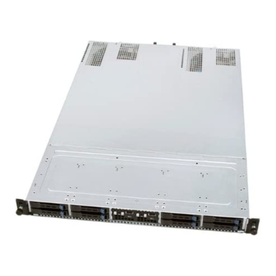
Server System Overview Intel® Server Board S5500HV/Intel® Server System SR1670HV TPS Intel Server System SR1670HV Overview ® ® The Intel Server System SR1670HV is an integrated 1U rack mount platform utilizing the ® features and functions of two Intel Server Boards S5500HV. -
Page 60: Front Panel Features
Intel® Server Board S5500HV/Intel® Server System SR1670HV TPS Server System Overview ® The Intel Server System SR1670HV supports the following feature set: ® Table 20. Intel Server System SR1670HV Feature Set Feature Description Chassis Form Factor 1U Rack Mount Server ®... -
Page 61: Rear Panel Features
Server System Overview Intel® Server Board S5500HV/Intel® Server System SR1670HV TPS Dual independent front control panels – one for each server node System ID LED System ID Button ® Figure 36. Intel Server System SR1670HV - Front Panel Overview Rear Panel Features The server system provides the following features on the system’s back panel:... -
Page 62: System Led Overview
Intel® Server Board S5500HV/Intel® Server System SR1670HV TPS Server System Overview System LED Overview Front Control Panel LEDs 8.3.1 The system provides two independent front control panels, one for each server node. Each control panel supports the following LEDs: Display Status... -
Page 63: Hard Drive Status Leds
RAID cards. For backplane FRU replacement, the entire hard drive bay is modular and can be removed from the chassis by removing 6 screws and sliding the entire bay assembly ® forward, then up and out of the chassis. See the Intel Server System SR1670HV Service Guide for more FRU replacement information. -
Page 64: System Cooling
Intel® Server Board S5500HV/Intel® Server System SR1670HV TPS Server System Overview Figure 42 Har driver Bay Assembly System Cooling The system provides a bank of four dual rotor system fans for each server node. Each bank of four system fans is independent of each other and controlled by the server node to which they are attached. -
Page 65: System Power
Server System Overview Intel® Server Board S5500HV/Intel® Server System SR1670HV TPS fan speeds will gradually increase to a maximum 100%. As CPU temperatures fall, fan speeds will automatically readjust to a lower speed. System Power The system includes two 770-Watt power supply modules and a power distribution board. Each power supply module provides power to a single server node. -
Page 66: Power Supply Module Specification
Intel® Server Board S5500HV/Intel® Server System SR1670HV TPS Server System Overview Figure 46. Power Module Removal Power Supply Module Specification 8.6.1 Table 21. Power Supply Module Specification Module Outputs 770 Watt: 62.5 Amps, 5VSB: 4 Amps Module Efficiency ~85% efficiency @ 20%, 230VAC... -
Page 67: Ac Power Cord Specification Requirements
Server System Overview Intel® Server Board S5500HV/Intel® Server System SR1670HV TPS and off due to a temperature recovery condition. The power supply shall alert the system of the OTP condition via the power supply FAIL signal and the PWR LED. -
Page 68: Environmental Specifications
Disclaimer Note: Intel Corporation server boards contain a number of high-density VLSI and power delivery components that need adequate airflow to cool. Intel ensures through its own chassis development and testing that when Intel server building blocks are used together, the fully integrated system will meet the intended thermal requirements of these components. -
Page 69: Intel Server System Sr1670Hv Environmental Specifications
Disclaimer Note: Intel Corporation server boards contain a number of high-density VLSI and power delivery components that need adequate airflow to cool. Intel ensures through its own chassis development and testing that when Intel server building blocks are used together, the fully integrated system will meet the intended thermal requirements of these components. -
Page 70: 10. Regulatory And Certification
Intel® Server Board S5500HV/Intel® Server System SR1670HV TPS Regulatory and Certification 10. Regulatory and Certification 10.1 Intel Server Board S5500HV Regulatory and Certification ® Intended Application – This product was evaluated as Information Technology Equipment (ITE), which may be installed in offices, schools, computer rooms, and similar commercial type locations. -
Page 71: Electromagnetic Compatibility Notices
Regulatory and Certification Intel® Server Board S5500HV/Intel® Server System SR1670HV TPS Compliance Regional Compliance Compliance Reference Marking Example Description Reference Japan VCCI Certification Korea KCC Certification 인증번호: CPU-Model Name (A) Taiwan BSMI CNS13438 D33025 Electromagnetic Compatibility Notices 10.1.1 10.1.1.1 This device complies with Part 15 of the FCC Rules. Operation is subject to the following two conditions: (1) this device may not cause harmful interference, and (2) this device must accept any interference received, including interference that may cause undesired operation. -
Page 72: Fcc Verification Statement
Intel® Server Board S5500HV/Intel® Server System SR1670HV TPS Regulatory and Certification Consult the dealer or an experienced radio/TV technician for help. Any changes or modifications not expressly approved by the grantee of this device could void the user’s authority to operate the equipment. The customer is responsible for ensuring compliance of the modified product. -
Page 73: Bsmi (Taiwan)
English translation of the notice above: 1. Type of Equipment (Model Name): On License and Product 2. Certification No.: On RRL certificate. Obtain certificate from local Intel representative 3. Name of Certification Recipient: Intel Corporation 4. Date of Manufacturer: Refer to date code on product 5. -
Page 74: Use Of Specified Regulated Components
URL: http://channel.intel.com/go/serverbuilder If you do not have access to Intel’s Web address, please contact your local Intel representative. Server chassis (base chassis is provided with power supply and fans) – UL listed. Server board – you must use an Intel server board – UL or other NRTL recognized. -
Page 75: Table 29. Server System Product Safety & Electromagnetic (Emc) Compliance
Regulatory and Certification Intel® Server Board S5500HV/Intel® Server System SR1670HV TPS The following table references Server System Compliance and markings that may appear on the product. Markings below are typical markings however, may vary or be different based on how certification is obtained. -
Page 76: Electromagnetic Compatibility Notices
Intel® Server Board S5500HV/Intel® Server System SR1670HV TPS Regulatory and Certification Compliance Regional Compliance Compliance Reference Marking Example Description Reference Korea KCC Certification 인증번호: CPU-Model Name (A) Russia GOST-R Certification Ukraine Ukraine Certification None Required Taiwan BSMI CNS13438 R33025 Electromagnetic Compatibility Notices 10.2.3... - Page 77 Regulatory and Certification Intel® Server Board S5500HV/Intel® Server System SR1670HV TPS Consult the dealer or an experienced radio/TV technician for help. Any changes or modifications not expressly approved by the grantee of this device could void the user’s authority to operate the equipment. The customer is responsible for ensuring compliance of the modified product.
-
Page 78: 10.3 Product Ecology Compliance
5. Manufacturer/Nation: Intel Corporation/Refer to country of origin marked on product 10.3 Product Ecology Compliance Intel has a system in place to restrict the use of banned substances in accordance with world wide product ecology regulatory requirements. The following is Intel’s product ecology compliance criteria. - Page 79 Regulatory and Certification Intel® Server Board S5500HV/Intel® Server System SR1670HV TPS Compliance Regional Compliance Reference Marking Compliance Reference Description Example California California Code of Regulations, Title 22, Division 4.5; Special handling may apply. Chapter 33: Best Management Practices for Perchlorate Materials.
-
Page 80: 10.4 Other Markings
Intel® Server Board S5500HV/Intel® Server System SR1670HV TPS Regulatory and Certification Compliance Regional Compliance Reference Marking Compliance Reference Description Example International ISO11469 - Plastic parts weighing >25gm are intended to be marked with per ISO11469. > < PC/ABS Recycling Markings – Fiberboard (FB) and Cardboard (CB) are marked with international recycling marks. -
Page 81: Component Regulatory Requirements To Support System And/Or Baseboard Level Certifications
CB Certificate & Report (International) Note: CB to include all CB national deviations) Certification marks to be visible on power supply. Power supply is to comply with the Intel power supply specification. Peripheral Devices (e.g. Disk Drives, CD ROMs) Minimum Certifications: UL, cUL Recognition (Canada/USA), CE DOC (Europe), One European Approval (e.g. - Page 82 Intel® Server Board S5500HV/Intel® Server System SR1670HV TPS Regulatory and Certification Connectors Requires being UL Recognized. Rated minimum V-0 and temperature wise suitably rated for its application. Cables/Wiring Harnesses (e.g. Ribbon cables) Requires being UL Recognized and temperature wise suitably rated for its application.
-
Page 83: 11. Product Safety Information
Product Safety Information Intel® Server Board S5500HV/Intel® Server System SR1670HV TPS 11. Product Safety Information ® ® This document applies to Intel Server Boards, Intel Server Chassis (pedestal and rack-mount) and installed peripherals. To reduce the risk of bodily injury, electrical shock, fire, and equipment damage, read this document and observe all warnings and precautions in this guide ®... -
Page 84: 11.3 Equipment Handling Practices
Intel® Server Board S5500HV/Intel® Server System SR1670HV TPS Product Safety Information In regions that are susceptible to electrical storms, we recommend you plug your system into a surge suppresser and disconnect telecommunication lines to your modem during an electrical storm. -
Page 85: Power Cord Warnings
Product Safety Information Intel® Server Board S5500HV/Intel® Server System SR1670HV TPS ADVARSEL! Lithiumbatteri - Eksplosionsfare ved fejlagtig håndtering. Udskiftning må kun ske med batteri af samme fabrikat og type. Levér det brugte batteri tilbage til leverandøren. ADVARSEL Lithiumbatteri - Eksplosjonsfare. Ved utskifting benyttes kun batteri som anbefalt av apparatfabrikanten. -
Page 86: 11.5 System Access Warnings
Intel® Server Board S5500HV/Intel® Server System SR1670HV TPS Product Safety Information 11.5 System Access Warnings CAUTION To avoid personal injury or property damage, the following safety instructions apply whenever accessing the inside of the product: Turn off all peripheral devices connected to this product. -
Page 87: 11.7 Cooling And Airflow
Product Safety Information Intel® Server Board S5500HV/Intel® Server System SR1670HV TPS 11.7 Cooling and Airflow CAUTION Carefully route cables as directed to minimize airflow blockage and cooling problems. For proper cooling and airflow, operate the system only with the chassis covers installed. -
Page 88: Appendix A: Product Usage Tips
Intel® Server Board S5500HV/Intel® Server System SR1670HV TPS Appendix A: Product Usage Tips Appendix A: Product Usage Tips When adding or removing components or peripherals from the server board, AC power must be removed. With AC power plugged into the server board, 5-Volt standby is still present even though the server board is powered off. -
Page 89: Glossary
Glossary Intel® Server Board S5500HV/Intel® Server System SR1670HV TPS Glossary This appendix contains important terms used in this document. For ease of use, numeric entries are listed first (e.g., “82460GX”) followed by alpha entries (e.g., “AGP 4x”). Acronyms are followed by non-acronyms. - Page 90 Intel® Server Board S5500HV/Intel® Server System SR1670HV TPS Glossary Term Definition ® Intel Architecture Input Buffer I/O Controller Hub ICMB Intelligent Chassis Management Bus IERR Internal Error I/O and Firmware Bridge Independent Loading Mechanism Integrated Memory Controller INTR Interrupt I/OAT...
- Page 91 Glossary Intel® Server Board S5500HV/Intel® Server System SR1670HV TPS Term Definition Platform Information Area (This feature configures the firmware for the platform hardware) Programmable Logic Device Platform Management Interrupt POST Power-On Self Test PSMI Power Supply Management Interface Pulse-Width Modulation...
-
Page 92: Reference Documents
Intel® Server Board S5500HV/Intel® Server System SR1670HV TPS Reference Documents Reference Documents Refer to the following documents for additional product information: ® Intel Server System SR1670HV Service Guide ® ® Intel Server Board S5500HV/Intel Server System SR1670HV Configuration Guide ®...
Need help?
Do you have a question about the Server Board S5500HV and is the answer not in the manual?
Questions and answers