Intel SR1625UR Technical Product Specification
Hide thumbs
Also See for SR1625UR:
- Service manual (186 pages) ,
- Quick start manual (1 page) ,
- Spares parts list & configuration manual (26 pages)
Table of Contents
Advertisement
Quick Links
Download this manual
See also:
Service Manual
Advertisement
Table of Contents

Related Manuals for Intel SR1625UR


Summary of Contents for Intel SR1625UR
- Page 1 Intel Server System SR1625UR ® Technical Product Specification Intel order number E47487-007 Revision 1.5 August, 2010 Enterprise Platforms and Services Division...
-
Page 2: Revision History
Intel products are not intended for use in medical, life saving, or life sustaining applications. Intel may make changes to specifications and product descriptions at any time, without notice. -
Page 3: Table Of Contents
Intel® Server System SR1625UR Table of Contents Table of Contents 1. Introduction ........................1 Chapter Outline ...................... 1 Server Board Use Disclaimer ................. 2 2. Product Overview ....................... 3 Processor Support ....................4 2.1.1 Processor Population Rules ................... 5 System Overview ....................7 System Dimensions .................... - Page 4 Table of Contents Intel® Server System SR1625UR TPS 3.6.7 AC Line 5 VSB Holdup ..................23 3.6.8 AC Line Leakage Current ..................23 3.6.9 Power Factor Correction ..................23 DC Output Specification ..................23 3.7.1 Output Power/Currents ..................23 3.7.2 Voltage Regulation ....................
- Page 5 Intel® Server System SR1625UR Table of Contents 7.3.2 SAS/SATA Backplane Functional Architecture ............. 53 8. Mini Control Panel Functionality ..................55 Mini Control Panel Buttons ................... 55 Mini Control Panel LED Indicators ................ 56 8.2.1 Power/Sleep LED ....................57 8.2.2 System Status LED ....................
- Page 6 Table of Contents Intel® Server System SR1625UR TPS 13.1.4 Certifications/Registrations/Declarations .............. 75 13.2 Product Regulatory Compliance Markings ............76 13.3 Rack Mount Installation Guidelines ..............78 13.4 Power Cord Usage Guidelines ................79 13.5 Electromagnetic Compatibility Notices ..............80 13.5.1 FCC Verification Statement (USA) ...............
- Page 7 Figure 9. Front Bezel Supporting Mini Control Panel..............14 Figure 10. Front Bezel Supporting Standard Control Panel ............14 ® Figure 11. Front Bezel Supporting Intel Local Control Panel ........... 15 Figure 12. Power Supply Module Enclosure - Dimensional Drawing ......... 16 Figure 13.
- Page 8 List of Figures Intel® Server System SR1625UR TPS Figure 33. Hot-Swap SAS/SATA Backplane (Front Side View) ..........52 Figure 34. Hot-Swap SAS/SATA Backplane (Back Side View) ..........52 Figure 35. SAS/SATA Backplane Functional Block Diagram ............ 53 Figure 36. Mini Control Panel Assembly Module ............... 55 Figure 37.
- Page 9 Intel® Server System SR1625UR List of Tables List of Tables Table 1. System Feature Set ...................... 3 Table 2. Mixed Processor Configurations ..................6 Table 2. System Dimensions ...................... 7 Table 3. Drive Overview ......................9 Table 4. Major Board Components ................... 12 Table 5.
- Page 10 List of Tables Intel® Server System SR1625UR TPS Table 32. PCI Express* x4 Slot Connector from Midplane ............40 Table 33. PCI Express* x4 Slot Connector from Midplane ............41 ® Table 34. Intel Local Control Panel (LCP) Connector .............. 42 Table 35.
- Page 11 Intel® Server System SR1625UR List of Tables Table 66. POST Error Beep Codes ................... 92 Table 67. Integrated BMC Beep Codes ..................93 Revision 1.5 Intel order number E47487-007...
- Page 12 List of Tables Intel® Server System SR1625UR TPS < This page is intentionally left blank.> Revision 1.5 Intel order number E47487-007...
-
Page 13: Introduction
EPS and EDS documents are not publicly available. They are only made available under NDA with Intel and must be ordered through your local Intel representative. See the Reference Documents section at the end of this document for a complete list of available documents. -
Page 14: Server Board Use Disclaimer
VLSI and power delivery components that need adequate airflow to cool. Intel ensures through its own system development and testing that when Intel server building blocks are used together, the fully integrated system will meet the intended thermal requirements of these components. -
Page 15: Product Overview
Intel® Server System SR1625UR TPS Product Overview Product Overview The Intel Server System SR1625UR is a rack mount 1U server system with features that are ® designed to support the high-density high-performance computing server market. The system is ® integrated with an Intel... -
Page 16: Processor Support
Thermal Design Power (TDP) up to 130 ,Only Quad Rank D Note: When configured with 130W processors IMMs are supported. ® ® The server boards do not support previous generations of the Intel Xeon Processors. Revision 1.5 Intel order number E47487-007... -
Page 17: Processor Population Rules
Processor Population Rules Note: Although the server board does support dual-processor configurations consisting of different processors that meet the defined criteria below, Intel does not perform validation testing of this configuation. For optimal system performance in dual-processor configurations, Intel recommends that identical processors be installed. -
Page 18: Table 2. Mixed Processor Configurations
Product Overview Intel® Server System SR1625UR TPS Table 2. Mixed Processor Configurations Error Severity System Action Processor family not Fatal The BIOS detects the error condition and responds as follows: identical Logs the error into the system event log (SEL). -
Page 19: System Overview
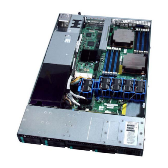
Intel® Server System SR1625UR TPS Product Overview System Overview Figure 1. Top Down View – Passive System Shown System Dimensions Table 3. System Dimensions 43.2 mm 1.70 in Height 430.0 mm 16.93 in Width without rails 470.0 mm 18.50 in Width with rails 665.5 mm... -
Page 20: System Components
I/O Expansion Module Connector Hard Drive Bays Front Bezel (Optional; Standard Control Riser Card Assembly Panel shown) ® Not shown: SAS/SATA Backplane; Standard Control Panel or Intel Local Control Panel Figure 2. Major System Components Revision 1.5 Intel order number E47487-007... -
Page 21: Hard Drive And Peripheral Bays
Mini Control Panel option, the system can support up to eight 2.5 inch ® drives. When configured with the Standard Control Panel or Intel Local Control Panel, the system can support up to six 2.5 inch drives. The slimline peripheral bay is capable of supporting one of the following devices: CD-ROM, DVD, or DVD-CDR. -
Page 22: System Board Overview
Product Overview Intel® Server System SR1625UR TPS System Board Overview ® Figure 4. Intel Server Board S5520UR The following figure shows the board layout of the server board. Each connector and major component is identified by a number or letter, and a description is given below the figure. -
Page 23: Figure 5. Intel Server Board S5520Ur Components
Intel® Server System SR1625UR TPS Product Overview ® Figure 5. Intel Server Board S5520UR Components Revision 1.5 Intel order number E47487-007... -
Page 24: Figure 6. Back Panel Feature Overview
Product Overview Intel® Server System SR1625UR TPS Table 5. Major Board Components Description Description ® ® 280-pin Intel Adaptive Riser Card Slot Fan Board Connector (Intel Server Chassis) POST Code LEDs 2x4 Power Connector ® Intel RMM3 Header Main Power Connector... -
Page 25: Figure 7. Intel
Intel® Server System SR1625UR TPS Product Overview AF002833 POST Code Diagnostic LEDs CPU 1 DIMM Fault LEDs System Identification LED CPU 2 Fan Fault LED Status LED Memory 2 Fan Fault LED Memory 1 Fan Fault LED CPU 2 DIMM Fault LEDs... -
Page 26: Front Bezel Support
Product Overview Intel® Server System SR1625UR TPS Front Bezel Support The optional front bezel is made of molded plastic and uses a snap-on design with a key lock. When installed, its design allows for maximum airflow. Figure 8. Optional Front Bezel Separate front bezels are available to support systems that use either a Mini Control Panel, ®... -
Page 27: Rack And Cabinet Mounting Options
Intel® Server System SR1625UR TPS Product Overview ® When the Intel Local Control Panel is used, the control panel module can be adjusted to extend further out from the chassis face to allow the LCD panel to protrude from the front bezel. -
Page 28: Power Subsystem
650 Watts of power. This chapter provides technical details on the operation of the power supply module and power ® subsystem. For additional information, refer to the Intel Server System SR1625 AC Power ® Supply Specification and the Intel Server System SR1625 Power Distribution Module Specification. -
Page 29: Dc Output Connection (Card Edge)
Intel® Server System SR1625UR TPS Power Subsystem 3.1.1 DC Output Connection (Card Edge) Bottom +12 V Ground Ground Figure 13. DC Output Connection (Card Edge) Single Power Supply Module Population In single power module configurations, the server management firmware requires that power supply module #1 be populated. -
Page 30: Handle And Retention Mechanism
Power Subsystem Intel® Server System SR1625UR TPS Configuring a single power supply module in the #2 module slot causes the server management firmware and BIOS to generate a system error during POST and the error is reported to the System Event Log. It also causes the system status LED on the control panel to blink green, denoting a degraded system configuration. -
Page 31: P1 - Server Board Power Connector
Intel® Server System SR1625UR TPS Power Subsystem 3.5.1 P1 – Server Board Power Connector Connector housing: 24-pin Molex* Mini-Fit Jr. 39-01-2245 or Intel approved equivalent Contact: Molex Mini-Fit, HCS, Female, Crimp 44476-1111 or Intel approved equivalent Table 7. P1 Main Power Connector Signal... -
Page 32: P3 - Power Signal Connector
+3.3 V Orange 3.5.5 P5 – Midplane Power Connector Connector housing: 10-pin Molex* Microfit PN # 43025-1000 or Intel approved equivalent Contact: Molex Microfit, Female, Crimp 43030-0007 or Intel approved equivalent Table 11. P5 Midplane Power Connector Signal 20 AWG Color... -
Page 33: Ac Input Requirements
Intel® Server System SR1625UR TPS Power Subsystem AC Input Requirements The power supply module incorporates universal power input with active power factor correction, which reduces line harmonics in accordance with the EN61000-3-2 and JEIDA MITI standards. 3.6.1 AC Inlet Connector The AC input connector is an IEC 320 C-14 power inlet. -
Page 34: Ac Input Voltage Specification
Power Subsystem Intel® Server System SR1625UR TPS 3.6.4 AC Input Voltage Specification The power supply must operate within all specified limits over the input voltage range shown in the following table: Table 14. AC Input Rating Startup Power-off Maximum Maximum Rated... -
Page 35: 3.6.7 Ac Line 5 Vsb Holdup
Intel® Server System SR1625UR TPS Power Subsystem The power supply must meet the AC inrush current requirements for any rated AC voltage, during turn-on at any phase of AC voltage, during a single cycle AC dropout condition as well as upon recovery after AC dropout of any duration, and over the specified temperature range , (includes hot and cold inrush). -
Page 36: Voltage Regulation
Power Subsystem Intel® Server System SR1625UR TPS 3.7.2 Voltage Regulation The power supply output voltages must stay within the voltage limits defined in the following table when operating at steady state and dynamic loading conditions. These limits include the peak-peak ripple/noise. All outputs are measured with reference to the return remote sense signal (ReturnS). -
Page 37: Over-Voltage Protection (Ovp)
Intel® Server System SR1625UR TPS Power Subsystem 3.8.2 Over-voltage Protection (OVP) Each DC/DC converter output on the PDB has individual OVP protection circuits built in and they are locally sensed. The PS and PDB shut down and latch off after an over-voltage condition occurs. -
Page 38: Cooling Subsystem
Cooling Subsystem Intel® Server System SR1625UR TPS Cooling Subsystem Several components and configuration requirements make up the cooling subsystem. These include the system fan module, the power supply fans, power supply air duct, CPU air duct, DIMM blanks, and drive bay population. All are necessary to provide and regulate the airflow and air pressure needed to maintain the system’s thermals when operating at or below... -
Page 39: Table 19. Fan Connector Pin Assingment
Intel® Server System SR1625UR TPS Cooling Subsystem The individual system fans are not hot-swappable and require the system to be turned off before being replaced. The chassis is classified as a “Service Access Only” device and caution should be exercised when replacing a system fan, as they do not have finger guards. However, provisions are built into the fan bracket to prevent accidental contact with the fan rotors. -
Page 40: Airflow Support
Cooling Subsystem Intel® Server System SR1625UR TPS Figure 17. Fan Header Assignments on Midplane Table 21. Fan Header Assignment Fan ID Midplane Fan Header Name Fan #1 – CPU2/System memory cooling FAN_1 Fan #2 – CPU2/System memory cooling FAN_2 Fan #3 – CPU1/System Memory cooling FAN_3 Fan #4 –... -
Page 41: Pci Riser Zone
Intel® Server System SR1625UR TPS Cooling Subsystem Figure 18. Power Supply Air Duct 4.2.2 PCI Riser Zone The PCI riser zone is the area between the power supply assembly and the PCI riser card of the riser assembly. The airflow through this area is generated by Fan 5 of the fan module. Air is drawn from the drive bay area through the fan and pushed out of the system through ventilation holes at the back of the chassis. -
Page 42: Dimm Blank Population
Cooling Subsystem Intel® Server System SR1625UR TPS Figure 19. Air Duct DIMM Blank Population DIMM Blanks are required in order to maintain adequate thermal levels and airflow. The requirements are as follows: One CPU installed – All CPU 1 DIMM (channels A, B, and C) slots must either have a DIMM or a DIMM blank installed. -
Page 43: Sata Hdd Support
Intel® Server System SR1625UR TPS Cooling Subsystem Figure 21. 2.5 inch Drive Blank Sata HDD Support Due to the rotational velocity and vibration impacts that fans have on hard drives, fan redundancy is only supported when using SAS hard drives. Additionally the maximum supported temperatures when using SATA drives have been affected as follows: ... -
Page 44: System Board Interconnects
System Board Interconnects Intel® Server System SR1625UR TPS System Board Interconnects System boards within the system include two types of midplanes, a bridge board, a hard drive backplane, a PCI riser board, and three types of control panels. This chapter describes the interconnect features of each and defines the pin-outs for each of their connectors. -
Page 45: Figure 23. Sas/Sas Raid Midplane Board
Intel® Server System SR1625UR TPS System Board Interconnects The system also supports an active SAS/SAS RAID midplane. This system board incorporates an LSI LSISAS1078 SAS controller onto the board. For information about SAS/SAS RAID support, see Chapter 6. The following figure shows the location for each connector found on this board. - Page 46 System Board Interconnects Intel® Server System SR1625UR TPS Signal Name Signal Name FAN_PRSNT5_N PE1_ESB_RX_DN_C2 PE1_ESB_RX_DP_C2 PE1_ESB_TX_DN1 PE1_ESB_TX_DP1 FAN_PRSNT4_N RST_PS_PWRGD PE1_ESB_RX_DN_C1 PE1_ESB_RX_DP_C1 PE1_ESB_TX_DN0 PE1_ESB_TX_DP0 RAID_KEY_PRES FM_RAID_MODE PE1_ESB_RX_DN_C0 PE1_ESB_RX_DP_C0 CLK_IOP_DN CLK_IOP_DP FAN_PRSNT1_N FAN_PRSNT3_N SGPIO_DATAOUT1 FAN_PRSNT2_N SGPIO_DATAOUT0 SGPIO_LOAD USB1_ESB_DP SGPIO_CLOCK USB1_ESB_DN USB2_ESB_DP USB1_ESB_OC_N...
-
Page 47: Table 22. Midplane Fan Header Pin-Outs
Intel® Server System SR1625UR TPS System Board Interconnects Signal Name Signal Name FAN_TACH8 FAN_TACH7 FAN_TACH6 FAN_TACH5 FAN_TACH4_H7 FAN_TACH3_H7 FAN_TACH2_H7 FAN_TACH1_H7 Table 23. Midplane Fan Header Pin-outs J2B1 - FAN_1 J2B3 - FAN_3 J7B1 - FAN_5 Pin Signal Name Pin Signal Name... -
Page 48: Table 24. Midplane-To-Backplane Card Edge Connector #1 Pin-Out
System Board Interconnects Intel® Server System SR1625UR TPS Table 25. Midplane-to-Backplane Card Edge Connector #1 Pin-out J7A1 - HSBP#1 I/F Signal Name Signal Name RST_PS_PWRGD SATA0_RX_N SATA0_RX_P SATA1_RX_N SATA1_RX_P SATA0_TX_N SATA0_TX_P SATA1_TX_P SATA1_TX_N USB2_ESB_DN USB2_ESB_DP USB2_ESB_OC_N SATA2_RX_N SATA2_RX_P SATA3_RX_N SATA3_RX_P... -
Page 49: Table 26. Active Midplane Sas Raid Battery Backup Connector Pin-Out
Intel® Server System SR1625UR TPS System Board Interconnects J4A1 - HSBP#2 I/F SATA_ADDIN2_TX_N SGPIO_LOAD SMB_PBI_3VSB_DAT SMB_IPMB_5VSB_DAT SMB_PBI_3VSB_CLK SMB_IPMB_5VSB_CLK USB0_ESB_OC_N USB1_ESB_DP USB1_ESB_DN USB0_ESB_DP USB0_ESB_DN USB1_ESB_OC_N LED_NIC1_ACT_N LED_HDD_ACTIVITY_N LED_NIC1_LINK_N LED_HDD_5V_A FM_SIO_TEMP_SENSOR FP_ID_SW_L LED_NIC2_LINK_N BMC_RST_BTN_N LED_NIC2_ACT_N FP_PWR_BTN_N FP_NMI_BTN_N V_BLUE_CONN_FP FP_PWR_LED_3VSB V_GREEN_CONN_FP FP_PWR_LED_R_N V_RED_CONN_FP... -
Page 50: Bridge Board
System Board Interconnects Intel® Server System SR1625UR TPS Table 28. Passive Midplane SATA/SAS Connector Pin-outs J5A2 - SAS_7 J6A1 - SAS_6 J5B1 - SAS_4 J6B1 - SAS_2 Signal Name Signal Name Signal Name Signal Name SATA_ADDIN1_TX_P SATA5_TX_P SATA3_TX_P SATA1_TX_P SATA_ADDIN1_TX_N... -
Page 51: Hot-Swap Sata/Sas Backplane
Intel® Server System SR1625UR TPS System Board Interconnects Hot-Swap SATA/SAS Backplane The hot-swap backplane provides support for both SAS and SATA hard drives. There are no hard drive cables that connect to the backplane. All hard drive control signals are routed from the midplane board, which plugs directly into the backplane. -
Page 52: Table 29. 1X7 Tape Drive Option Power Connector Pin-Out (J2N2)
System Board Interconnects Intel® Server System SR1625UR TPS Table 30. 1x7 Tape Drive Option Power Connector Pin-out (J2N2) Pin # Signal Name P12V Ground Ground SASS_PRSTNT_L LED_SASS_ACT_L P3V3 Table 31. Slimline Optical Drive Slot Connector (J6C1) Pin # Signal Name... - Page 53 Intel® Server System SR1625UR TPS System Board Interconnects Pin # Signal Name Pin # Signal Name USB_OC1_N Ground Ground USB_P2P Ground USB_P2N USB_P1P Ground USB_P1N Ground Ground USB_OC2_N LED_NIC1_ACT_L LED_HDD_ACT_R_L LED_NIC1_LINK_R_L PV_HDD_LED_3V_A FP_THERM_SENSOR FP_ID_SW_L LED_NIC2_LINK_R_L RST_FP_BTN_L LED_NIC2_ACT_L FP_PWR_BTN_L Ground FP_NMI_BTN_L...
- Page 54 System Board Interconnects Intel® Server System SR1625UR TPS ® Table 35. Intel Local Control Panel (LCP) Connector Pin # Signal Description SMB_IPMB_5VSB_DAT Ground SMB_IPMB_5VSB_CLK P5V_STBY_R Table 36. Control Panel Signal Connector Pin # Signal Name Pin # Signal Name V_IO_RED_CONN_FP...
- Page 55 Intel® Server System SR1625UR TPS System Board Interconnects Table 38. SAS/SATA Hard Drive Connector Pin-outs Pin# Signal Description Ground SAS#_TX_DP (# = 0…7) SAS#_TX_DN (# = 0…7) Ground SAS#_RX_DN (# = 0…7) SAS#_RX_DP (# = 0…7) Ground Not Used Not Used...
-
Page 56: Peripheral Drive Support
Once it is inserted into the system, the assembly locks into place. It is not hot-swappable. For removal, the system must be powered down, the chassis top cover ® removed and the locking latch disengaged. For additional details, see the Intel Server System SR1625UR Service Guide. - Page 57 Intel® Server System SR1625UR TPS Peripheral Drive Support Pin # Signal Name Revision 1.5 Intel order number E47487-007...
-
Page 58: Hard Disk Drive Support
Hard Disk Drive Support Intel® Server System SR1625UR TPS Hard Disk Drive Support The system can be configured to support several different hard drive and peripheral configurations. The peripheral/hard drive subsystem consists of a drive bay supporting a slimline optical drive, and hard drives; a midplane; and a hot-swap backplane. This chapter describes the details for each subsystem component. -
Page 59: Midplane Options
Intel® Server System SR1625UR TPS Hard Disk Drive Support 2.5 inch hard drive Four screws to mount the hard drive Hard drive carrier Green touch point to extract the carrier Figure 29. Hard Drive Tray Assembly Midplane Options The midplane is designed and used, along with that of the bridge board and hot-swap backplane, to improve cable routing within the system. -
Page 60: Active Midplane With Intel
Hard Disk Drive Support Intel® Server System SR1625UR TPS Power Connector Fan 4 Connector Fan 6 Connector Fan 3 Connector Fan 5 Connector Fan 1 Connector SAS/SATA Connectors Fan 2 Connector Bridge Board Connector Backplane Connector Figure 30. Passive Midplane Board 7.2.2... -
Page 61: Figure 31. Active Midplane With Sas/Sas Raid Support
Intel® Server System SR1625UR TPS Hard Disk Drive Support RAID Battery Backup Unit Fan 4 Connector Connector Power Connector Fan 3 Connector Mini-DIMM Connector Fan 1 Connector Fan 6 Connector Fan 2 Connector RAID Activation Key Fan 5 Connector Connector... -
Page 62: Figure 32. Active Midplane Architecture Diagram
The active midplane supports options to provide full hardware RAID support. Options required ® to enable hardware RAID support include an Intel RAID Activation Key (Product Order Code – AXXRAKSAS2) and installation of a Mini-DIMM (Product Order Code – AXXMINIDIMM512) for ®... -
Page 63: Hot-Swap Sas/Sata Backplane
DIMM connector (J8C1), supporting a single registered ECC non-parity DDR2-667 MHz Mini- DIMM to provide Intel RAID cache. Supported mini-DIMM capacities range from 128 MB to 1 Note: For a list of Intel validated mini-DIMMs, use the Server Configurator Tool available at http://serverconfigurator.intel.com/default.aspx. -
Page 64: Figure 33. Hot-Swap Sas/Sata Backplane (Front Side View)
Hard Disk Drive Support Intel® Server System SR1625UR TPS Slimline Optical Device Connector SAS/SATA hot-swap Connectors Mini Control Panel Connector Figure 33. Hot-Swap SAS/SATA Backplane (Front Side View) USB Connector Card Edge Connectors to Midplane Power Connector 10-pin Control Panel Connector Figure 34. -
Page 65: Sas/Sata Backplane Functional Architecture
Intel® Server System SR1625UR TPS Hard Disk Drive Support 7.3.2 SAS/SATA Backplane Functional Architecture The following figure shows the functional blocks of the SAS/SATA backplane. Figure 35. SAS/SATA Backplane Functional Block Diagram 7.3.2.1 Enclosure Management Controller The backplane utilizes the features of the Vitesse VSC410 to implement several enclosure management functions. - Page 66 Hard Disk Drive Support Intel® Server System SR1625UR TPS Amber On HDD Fault The activity LED functionality is controlled directly by the hard drives. This causes the LED to function differently between SAS and SATA drives. The expected operation is outlined in the following table.
-
Page 67: Mini Control Panel Functionality
Intel® Server System SR1625UR TPS Mini Control Panel Functionality Mini Control Panel Functionality For system configurations that require eight 2.5 inch hard drives, a mini control panel is used in place of the standard control panel. The mini control panel is modular in design and supports several push buttons and status LEDs, along with one USB port within a very compact design. -
Page 68: Mini Control Panel Led Indicators
Mini Control Panel Functionality Intel® Server System SR1625UR TPS Table 42. Mini Contol Panel Button Functions Reference Feature Function ID Button Toggles the front panel ID LED and the server board ID LED on/off. The server board ID LED is visible through the rear of the system and allows for server identification and location when working behind a rack of servers. -
Page 69: Power/Sleep Led
Intel® Server System SR1625UR TPS Mini Control Panel Functionality 8.2.1 Power/Sleep LED Table 44. SSI Power LED Operation State Power Mode Description Power-off Non-ACPI System power is off, and the BIOS has not initialized the chipset. Power-on Non-ACPI System power is on, but the BIOS has not yet initialized the chipset. -
Page 70: System Identification Led
Mini Control Panel Functionality Intel® Server System SR1625UR TPS Color State Criticality Description Processor 1 missing Temperature (e.g., CPU ThermTrip, memory TempHi, critical threshold crossed) No power good – power fault Processor configuration error (e.g., processor stepping mismatch) 8.2.3... -
Page 71: Figure 39. Mini Control Panel Pcb
Intel® Server System SR1625UR TPS Mini Control Panel Functionality Figure 39. Mini Control Panel PCB Table 47. 20-pin Mini Control Panel Interconnect Pin # Signal Name Pin # Signal Name FP_PWR_LED_R_L FP_PWR_BTN_L FP_SYS_FLT_LED1_R_L FAULT_LED_5VSB FP_SYS_FLT_LED2_R_L FP_NMI_BTN_L P5V_STBY_PWRLED_ANODE BP_I2C_5V_SCL 1_WIRE_BUS BP_I2C_5V_SDA... -
Page 72: Standard Control Panel Functionality
Standard Control Panel Functionality Intel® Server System SR1625UR TPS Standard Control Panel Functionality The standard control panel supports several push buttons and status LEDs, along with USB and video ports to centralize system control, monitoring, and accessibility within a compact design. -
Page 73: Standard Control Panel Led Indicators
Intel® Server System SR1625UR TPS Standard Control Panel Functionality Table 48. Standard Contol Button and Intrusion Switch Functions Reference Feature Function Power/Sleep Toggles the system power on/off. This button also functions as a Sleep Button button if enabled by an ACPI-compliant operating system. -
Page 74: Power/Sleep Led
Standard Control Panel Functionality Intel® Server System SR1625UR TPS Table 49. Standard Control Panel LED Functions Reference Color State Description Green NIC Link NIC1/NIC2 Activity Green Blink NIC Activity Green Legacy power on/ACPI S0 state Power/Sleep Blink Sleep/ACPI S1 state... -
Page 75: System Status Led
Intel® Server System SR1625UR TPS Standard Control Panel Functionality 9.2.2 System Status LED Table 51. Control Panel LED Operation Color State Criticality Description Not ready AC power off Green Solid on System booted and ready Green Blink Degraded System degraded ... -
Page 76: System Identification Led
Standard Control Panel Functionality Intel® Server System SR1625UR TPS 9.2.4 System Identification LED The blue system identification LED is used to help identify a system for servicing. This is especially useful when the system is installed in a high density rack or cabinet that is populated with several similar systems. -
Page 77: Figure 43. Standard Control Panel Pcb
Intel® Server System SR1625UR TPS Standard Control Panel Functionality Figure 43. Standard Control Panel PCB Table 54. 50-pin Standard Control Panel Signal Connector Pin # Signal Name Pin # Signal Name V_IO_RED_CONN_FP V_IO_GREEN_CONN_FP V_IO_BLUE_CONN_FP V_IO_HSYNC_BUFF_FP_L V_IO_VSYNC_BUFF_FP_L V_VIDEO_IN_USE FP_THERM_SENSOR SP_DTR2_L SP_DCD2_L... -
Page 78: Intel Local Control Panel Functionality
Intel® Local Control Panel Functionality Intel® Server System SR1625UR TPS 10. Intel Local Control Panel Functionality ® ® The Intel Local Control Panel (LCP) utilizes a combination of control buttons, LEDs, and LCD display to provide system accessibility, monitoring, and control functions. The pre-assembled module slides into a slot on the front of the chassis where it is cabled to the backplane. -
Page 79: 10.1 Led Functionality
Intel® Server System SR1625UR TPS Intel® Local Control Panel Functionality 10.1 LED Functionality The following table identifies each LED and describes their functionality: Table 56. LCP Control Panel LED Functions Color State Description Green NIC Link NIC1/NIC2 Activity Green Blink... -
Page 80: System Status Led
Intel® Local Control Panel Functionality Intel® Server System SR1625UR TPS 10.1.2 System Status LED Table 58. Control Panel LED Operation Color State Criticality Description Not ready AC power off Green Solid on System booted and ready Green Blink Degraded System degraded ... -
Page 81: Intel ® Local Control Panel Interconnects
Local Control Panel interface board and USB interface board are cabled to matching connectors on the hot-swap backplane. This ® section defines the pin-out for each connector and header found on both the Intel Local Control Panel interface board and interposer board. - Page 82 Intel® Local Control Panel Functionality Intel® Server System SR1625UR TPS Table 60. 10-pin Control Panel USB Connector Pin # Signal Description P5V_USB_P1 USB_P1N USB_P1P P5V_USB_P2 USB_P2N USB_P2P Table 61. Internal NMI/Temp Sensor Header Pin # Description DGND FP_NMI_BTN_L +3_3VSB 1_WIRE_BUS Revision 1.5...
-
Page 83: 11. Pci Riser Cards And Assembly
® The Intel Server System SR1625UR provides one x16 PCI Express* Gen 2 PCI riser slot capable of supporting a full-length full-height PCI Express* add-in card. When re-inserting the riser assembly into the system, tabs on the back of the assembly should be aligned with slots on the back edge of the system. -
Page 84: 12. Environmental Specifications
Vibration, unpackaged 5 Hz to 500 Hz, 2.20 g RMS random Shock, operating Half sine, 2 g peak, 11 milliseconds ® +/-15 KV except I/O port +/- 8 KV per Intel Environmental test specification System Cooling 2550 BTU/hour Requirement in BTU/Hr Operating Temperature +10°C to +35°C with the maximum rate of change not to exceed 10°C per hour... -
Page 85: 12.3 Replacing The Backup Battery
Intel® Server System SR1625UR TPS Environmental Specifications 12.3 Replacing the Backup Battery The lithium battery on the server board powers the real time clock (RTC) for up to 10 years in the absence of power. When the battery starts to weaken, it loses voltage, and the server settings stored in CMOS RAM in the RTC (e.g., the date and time) may be wrong. -
Page 86: 13. Regulatory And Certification Information
EMC compliance testing. For more information please contact your local Intel Representative. This is an FCC Class A device. Integration of it into a Class B chassis does not result in a Class B device. -
Page 87: Product Emc Compliance - Class A Compliance
13.1.3 Product Ecology Compliance Intel has a system in place to restrict the use of banned substances in accordance with world wide regulatory requirements. A Material Declaration Data Sheet is available for Intel products. For more reference on material restrictions and compliance you can view Intel’s Environmental Product Content Specification at http://supplier.intel.com/ehs/environmental.htm. -
Page 88: 13.2 Product Regulatory Compliance Markings
Packaging & Product Recycling Marks 13.2 Product Regulatory Compliance Markings This Intel Server Chassis product if provided with the following regulatory and safety markings. In the event there is no room for a marking(s) on the chassis, the information is provided here in this document. - Page 89 Intel® Server System SR1625UR TPS Regulatory and Certification Information Regulatory Compliance Country Marking GOST R Marking Russia KCC Mark (Korean Korea Communications Comission) Belarus Safety Belarus Compliance Mark Waste of Electronic and Europe Electrical Equipment Recycling Mark China Restriction of...
-
Page 90: 13.3 Rack Mount Installation Guidelines
Regulatory and Certification Information Intel® Server System SR1625UR TPS Regulatory Compliance Country Marking 本设备包括多条电源系统电缆。为避免遭受电击,在进行维 修之前应断开两(2)条电源系统电缆。 Traditional Chinese: 注意: 本設備包括多條電源系統電纜。為避免遭受電擊,在進行維 修之前應斷開兩(2)條電源系統電纜。 German: Dieses Geräte hat mehr als ein Stromkabel. Um eine Gefahr des elektrischen Schlages zu verringern trennen sie beide (2) Stromkabeln bevor Instandhaltung. -
Page 91: 13.4 Power Cord Usage Guidelines
Intel® Server System SR1625UR TPS Regulatory and Certification Information Overcurrent protection: The server is designed for an AC line voltage source with up to 20 amperes of overcurrent protection per cord feed. If the power system for the equipment rack is installed on a branch circuit with more than 20 amperes of protection, you must provide supplemental protection for the server. -
Page 92: 13.5 Electromagnetic Compatibility Notices
Regulatory and Certification Information Intel® Server System SR1625UR TPS certification by an agency acceptable in your region and for U.S. must be Listed and rated 125% of overall current rating of the server. Connector, server end: The connectors that plug into the AC receptacle on the server must be an approved IEC (International Electrotechnical Commission) 320, sheet C13, type female connector. -
Page 93: Ices-003 (Canada)
Intel® Server System SR1625UR TPS Regulatory and Certification Information 13.5.2 ICES-003 (Canada) Cet appareil numérique respecte les limites bruits radioélectriques applicables aux appareils numériques de Classe Aprescrites dans la norme sur le matériel brouilleur: “Appareils Numériques”, NMB-003 édictée par le Ministre Canadian des Communications. -
Page 94: Kcc (Korea)
Updated product information for configurations can be found on the Intel Server Builder Web site at the following URL: http://channel.intel.com/go/serverbuilder If you do not have access to Intel’s Web address, please contact your local Intel representative. Server chassis (base chassis is provided with power supply and fans) — UL listed. -
Page 95: Appendix A: Integration And Usage Tips
Appendix A: Integration and Usage Tips Appendix A: Integration and Usage Tips ® This section provides a list of useful information that is unique to the Intel Server System ® SR1625UR and should be kept in mind while integrating and configuring your Intel Server Board S5520UR. -
Page 96: Appendix B: Post Code Diagnostic Led Decoder
Appendix B: POST Code Diagnostic LED Decoder Intel® Server System SR1625UR TPS Appendix B: POST Code Diagnostic LED Decoder During the system boot process, the BIOS executes a number of platform configuration processes, each of which is assigned a specific hex POST code number. As each configuration routine is started, the BIOS displays the POST code to the POST Code Diagnostic LEDs on the back edge of the server board. - Page 97 Intel® Server System SR1625UR TPS Appendix B: POST Code Diagnostic LED Decoder Table 65. Diagnostic LED POST Code Decoder Diagnostic LED Decoder O = On, X=Off Checkpoint Upper Nibble Lower Nibble Description Multi-use code (This POST Code is used in different contexts)
- Page 98 Appendix B: POST Code Diagnostic LED Decoder Intel® Server System SR1625UR TPS Diagnostic LED Decoder O = On, X=Off Checkpoint Upper Nibble Lower Nibble Description 0x52h Hot Plug PCI controller initialization 0x53h Reserved for PCI bus 0x54h Reserved for PCI bus...
- Page 99 Intel® Server System SR1625UR TPS Appendix B: POST Code Diagnostic LED Decoder Diagnostic LED Decoder O = On, X=Off Checkpoint Upper Nibble Lower Nibble Description etc.) 0xBCh Enabling/configuring a removable media device Boot Device Selection (BDS) 0xD0 Trying to boot device selection 0...
- Page 100 Appendix B: POST Code Diagnostic LED Decoder Intel® Server System SR1625UR TPS Diagnostic LED Decoder O = On, X=Off Checkpoint Upper Nibble Lower Nibble Description Has been called) OS has requested the system to reset (ResetSystem ( ) has been...
-
Page 101: Appendix C: Post Code Errors
Intel® Server System SR1625UR TPS Appendix C: POST Code Errors Appendix C: POST Code Errors Whenever possible, the BIOS outputs the current boot progress codes on the video screen. Progress codes are 32-bit quantities plus optional data. The 32-bit numbers include class, subclass, and operation information. - Page 102 Appendix C: POST Code Errors Intel® Server System SR1625UR TPS Error Code Error Message Response 8140 Processor 01 Failed FRB-3 Timer. No Pause 8141 Processor 02 Failed FRB-3 Timer. No Pause 8160 Processor 01 unable to apply BIOS update Pause...
- Page 103 Intel® Server System SR1625UR TPS Appendix C: POST Code Errors Error Code Error Message Response 856A DIMM_C3 Component encountered a Serial Presence Detection (SPD) fail error. Pause 856B DIMM_C4 Component encountered a Serial Presence Detection (SPD) fail error. Pause 856C DIMM_D1 Component encountered a Serial Presence Detection (SPD) fail error.
-
Page 104: Post Error Beep Codes
The beep code is followed by a ® user-visible code on POST progress LEDs. For complete details, refer to the Intel S5500/S5520 Server Board Family BIOS External Product Specification. Table 67. POST Error Beep Codes... - Page 105 Intel® Server System SR1625UR TPS Appendix C: POST Code Errors Table 68. Integrated BMC Beep Codes Code Reason for Beep Associated Sensors Supported? 1-5-2-1 CPU: Empty slot/population error – Processor CPU Population Error slot 1 is not populated. 1-5-4-2 Power fault: DC power unexpectedly lost (power Power Unit –...
-
Page 106: Glossary
Glossary Intel® Server System SR1625UR TPS Glossary Word/Acronym Definition Australian Communication Authority ANSI American National Standards Institute Baseboard Management Controller BIOS Basic Input/Output System CMOS Complementary Metal-oxide-semiconductor DC-to-DC Emergency Management Port Front Panel Fault Resilient Boot Field Replaceable Unit Inter-integrated Circuit bus... -
Page 107: Reference Documents
See the following documents for additional information: ® Intel Server Board S5520UR Technical Product Specification ® Intel Server System SR1625UR AC Power Supply Module Specification ® ® Intel Server Board S5520UR/Intel Server System SR1625UR Spares/Parts List and Configuration Guide ®...
Need help?
Do you have a question about the SR1625UR and is the answer not in the manual?
Questions and answers