
Related Manuals for Intel SR1680MV - Server System - 0 MB RAM


Summary of Contents for Intel SR1680MV - Server System - 0 MB RAM
- Page 1 ® Intel Server System SR1680MV Service Guide A Guide for Technically Qualified Assemblers of Intel® Identified Subassemblies/Products Intel Order Number E74835-005...
- Page 2 Intel products are not designed, intended or authorized for use in any medical, life saving, or life sustaining applications or for any other application in which the failure of the Intel product could create a situation where personal injury or death may occur.
-
Page 3: Preface
Manual Organization ® Chapter 1 provides a brief overview of the Intel Server System SR1680MV. In this chapter, you will find a list of the system features, photos of the product, and product diagrams to help you identify components and their locations. -
Page 4: Product Contents, Order Options, And Accessories
Processor, memory DIMMs, hard drive, and operating system. For information about which accessories, memory, processors, and third-party hardware were tested and can be used with your board, and for ordering information for Intel products, see http://support.intel.com/support/motherboards/server/SR1680MV/compat.htm. - Page 5 If you just received this Intel Server System SR1680MV Quick Start User's Guide in the product and need to product box install it Accessories or other Intel Spares and Configuration Guide server products Hardware (peripheral Tested Hardware Operating Systems List boards, adapter cards,...
- Page 6 ® Intel Server System SR1680MV Service Guide...
-
Page 7: Safety Information
Safety Information Important Safety Instructions Read all caution and safety statements in this document before performing any of the instructions. See also Intel Server Boards and Server Chassis Safety Information on the ® Intel Server Resource CD and/or at http://support.intel.com/support/motherboards/ server/sb/cs-010770.htm. - Page 8 ® viii Intel Server System SR1680MV Service Guide...
-
Page 9: Warnings
Take care to grip with, but not squeeze, the pliers or other tool you use to remove a jumper, or you may bend or break the pins on the board. ® Intel Server System SR1680MV Service Guide... - Page 10 ® Intel Server System SR1680MV Service Guide...
-
Page 11: Table Of Contents
Removing the Heatsink ....................16 Installing the Heatsink ....................17 System Memory ......................17 System Memory Channel Population Requirements for Memory RAS Modes ....19 Independent Channel Mode ..................19 Mirrored Channel Mode ....................19 Lockstep Channel Mode ....................19 ® Intel Server System SR1680MV Service Guide... - Page 12 10 GB IO Card (Optional Daughter Card) ................52 InfiniBand Card (Optional Daughter Card) ................53 Connector and Component Locations of HDD Backplane ..........54 Connectors and Component Locations of PDB ..............55 ® Intel Server System SR1680MV Service Guide...
- Page 13 Enabling RAID in the BIOS Setup ................99 Chapter 7: Installing the Rackmount Rail Kits ............. 101 Procedure to install the rail kit ....................102 ® Appendix A: Intel Server Issue Report Form ............. 105 Appendix B: Troubleshooting ................111 Resetting the System ......................111 Problems following Initial System Installation ..............111...
- Page 14 Autres risques ......................144 Español ..........................145 Información de seguridad del servidor ..............145 Advertencias y precauciones sobre seguridad ............145 Aplicaciones y usos previstos ................... 146 Selección de la ubicación ..................146 ® Intel Server System SR1680MV Service Guide...
- Page 15 ICES-003 (Canada) ....................169 CE Declaration of Conformity (Europe) ..............169 VCCI (Japan) ......................169 BSMI (Taiwan) ......................170 KCC (Korea) ......................170 Regulated Specified Components ..................170 Appendix F: Warranty .................... 173 Appendix G: Getting Help ..................175 ® Intel Server System SR1680MV Service Guide...
- Page 16 ® Intel Server System SR1680MV Service Guide...
- Page 17 List of Figures ® Figure 1. Intel Server System SR1680MV with 2.5-inch Pluggable HDDs......1 Figure 2. Layout of Server Chassis with 2.5-inch Pluggable HDDs .......... 3 Figure 3. Front View of Server with 2.5-inch Pluggable HDDs..........4 Figure 4. Back View ........................5 Figure 5.
- Page 18 Figure 67. Secure the Rail to Racks ..................103 Figure 68. Slide The Server Into Racks ................103 Figure 69. Push The Server To The End Of Racks .............. 104 Figure 70. Secure The Server Ears To Racks ..............104 ® xviii Intel Server System SR1680MV Service Guide...
- Page 19 List of Tables ® Table 1. Intel Server System SR1680MV Feature Summary ..........2 Table 2. LED Information ......................6 Table 3. Ideal DIMM Installation Options for A-C Channels of Processor 1 ......20 Table 4. Ideal DIMM Installation Options for D-F Channels of Processor 2 ......20 Table 5.
- Page 20 Table 46. Resetting the System .................... 111 Table 47. LED Information ....................116 Table 48. POST Error Beep Codes ..................116 ® Table 49. Error Beep Codes Generated by Intel Management Module ......117 Table 50. Product Regulatory Compliance Markings ............160 ®...
-
Page 21: Chapter 1: Server System Features
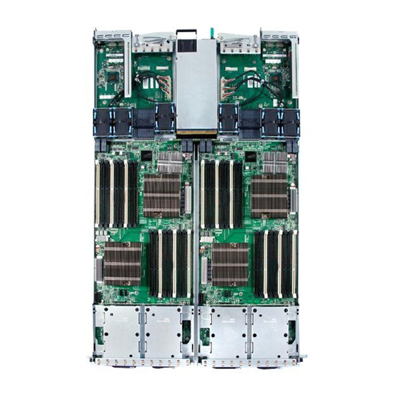
Figure 1. Intel Server System SR1680MV with 2.5-inch Pluggable HDDs The sever supports two identical motherboards, left and right I/O boards. Two I/O boards ® have the same function with different placement. Based on the Intel 5500 chipset ® ®... -
Page 22: Table 1. Intel ® Server System Sr1680Mv Feature Summary
• 714.2 mm depth • Minimum weight: 11.7 kg • Maximum weight: 17.16 kg • ® ® Processor Support for up to four Intel Xeon Processor 5500 Series and ® ® Intel Xeon 5600 Series (two per server node) •... -
Page 23: System Overview
3. PCI-E Cage 8. Pluggable HDD Bays 4. System Fans 9. NIC Card 5. Power Distribution Board 10. GB I/O Card or InfiniBand* Card (optional) Figure 2. Layout of Server Chassis with 2.5-inch Pluggable HDDs ® Intel Server System SR1680MV Service Guide... -
Page 24: Front View Components
12. 2.5-inch Pluggable HDDs Figure 3. Front View of Server with 2.5-inch Pluggable HDDs Back View Components The server back view includes connectors, buttons, and system LEDs of both internal and external devices. ® Intel Server System SR1680MV Service Guide... -
Page 25: Buttons And System Leds
The following figures shows the front panel: 1. NIC LED 5. UID LED 2. System Health LED 6. Power LED 3. Power Button 7. HDD LED 4. UID Button Figure 5. Front Panel Buttons and LEDs of Server ® Intel Server System SR1680MV Service Guide... -
Page 26: Rear Panel Button And Leds
Description Front View LEDs Power LED Amber On: System has AC power but in standby mode. Green On: System has AC power and is turned on. Off: No AC power to the system. ® Intel Server System SR1680MV Service Guide... - Page 27 Off: No connection UID LED Blue Blinking: System is being remotely managed On: Identification Off: Disabled AC Power LED Green On: +12V is output Off: No AC on or no main power on ® Intel Server System SR1680MV Service Guide...
- Page 28 ® Intel Server System SR1680MV Service Guide...
-
Page 29: Chapter 2: Hardware Installations And Upgrades
Note: The components shown in this chapter are mainly for your reference. Please take the actual shipment as standard. Tools and Supplies Needed • Phillips* (cross head) screwdriver (#1 bit and #2 bit) • Needle nosed pliers • Antistatic wrist strap and conductive foam pad (recommended) ® Intel Server System SR1680MV Service Guide... -
Page 30: System References
Disconnect all power cords from the server to completely remove power from the system. Pressing the Power Button Press the power button (“1”) to toggle the serve to hibernation. The power LED (“2”) in TBD turns off. Figure 7. Pressing the Power Button ® Intel Server System SR1680MV Service Guide... -
Page 31: Mid-Top Cover
2. Press down the locking button along the direction of the arrow. 3. Simultaneously slide the mid-top cover forward in the direction of the arrow using the traction pad, and then lift it up. ® Intel Server System SR1680MV Service Guide... -
Page 32: Central Processing Unit (Cpu)
® ® ® for the Intel Xeon Processor 5500 series and Intel Xeon Processor 5600 series. One server node can be configured to either a single- or dual-processor system. The following figure shows the location of processors on the motherboard: Figure 10. -
Page 33: Removing The Processor
“Mid-Top Cover”. Removing the Processor 1. Unlock the load lever and lift it up. 2. Open the load plate. Figure 11. Opening the Load Plate 3. Lift the processor out of the socket. ® Intel Server System SR1680MV Service Guide... -
Page 34: Figure 12. Lifting The Processor Out Of The Socket
Figure 12. Lifting the Processor Out of the Socket 4. Place the PnP cap onto the load plate. Figure 13. Placing on the PnP Cap ® Intel Server System SR1680MV Service Guide... -
Page 35: Installing The Processor
Installing the Processor Reverse the steps in “Removing the Processor” to install the processor. However, when inserting the processor into the socket, make sure the golden corner on the processor is pointed toward the socket. ® Intel Server System SR1680MV Service Guide... -
Page 36: Removing The Heatsink
If the processor does not fit completely, check its orientation or check for bent pins Removing the Heatsink 1. Loosen the two securing screws. 2. Lift the heatsink up from the installed processor. ® Intel Server System SR1680MV Service Guide... -
Page 37: Installing The Heatsink
Mixed memory is neither tested nor supported. Non-ECC memory is not tested and is not recommended for use in a server environment. The location of DIMM sockets on the motherboard is shown in Figure 17: ® Intel Server System SR1680MV Service Guide... -
Page 38: Figure 17. Location Of System Memories
Figure 17. Location of System Memories There are 18 DIMMs on the motherboard to support processor 1 and processor 2. The DIMM sequence of 18 DIMM sockets is respectively shown in Figure 18. Figure 18. DIMM Socket Location ® Intel Server System SR1680MV Service Guide... -
Page 39: System Memory Channel Population Requirements For Memory Ras Modes
For your reference, Table 3 offers an ideal DIMM population option for A-F channels of processor 1 and 2. The last column in tables marks DIMM installation under Mirrored Channel Mode for your reference. ® Intel Server System SR1680MV Service Guide... -
Page 40: Table 3. Ideal Dimm Installation Options For A-C Channels Of Processor 1
It is highly recommended that all DIMMs with same part number be used within one motherboard. For Unbuffered DIMMs or Quad-rank Registered DIMMs, only configuration 1~6 could be supported. Optional Note: For other Registered DIMMs, configuration 1~9 could be supported. ® Intel Server System SR1680MV Service Guide... -
Page 41: Removing A Dimm
2. Lift out the DIMM. Figure 19. Lifting the DIMM Out of the Socket Installing a DIMM 1. Unlock a DIMM socket by pressing the retaining clips outward. ® Intel Server System SR1680MV Service Guide... -
Page 42: Figure 20. Pressing The Retaining Clips Outward
2. Align the notch on the DIMM to the break on the socket. Carefully insert the DIMM into the socket until the retaining clips snap back in place. Figure 21. Inserting the DIMM into the Socket ® Intel Server System SR1680MV Service Guide... -
Page 43: Server Board Cage Module
Removing the Server Board Cage Module 1. Slide the locking latch along the direction of the arrow. 2. The cage locking lever springs open by itself. Figure 23. Releasing the Locking Latch ® Intel Server System SR1680MV Service Guide... -
Page 44: Figure 24. Pull The Locking Lever To Remove The Server Board Cage Module
Figure 24. Pull the Locking Lever to Remove the Server Board Cage Module Installing the Server Board Cage Module Reverse the “Removing the Server Board Cage Module” steps to install the server board cage module. ® Intel Server System SR1680MV Service Guide... -
Page 45: Left And Right I/O Board Cage Modules
“Power Off”. 2. Disconnect all necessary cable connections. 3. When removing and installing I/O board cage module, keep the handle of the power supply in the horizontal direction to avoid damage on it. ® Intel Server System SR1680MV Service Guide... -
Page 46: Removing The Left I/O Board Cage Module
Figure 28. Pull the Locking Lever to Remove the Left I/O Board Cage Module Installing the Left I/O Board Cage Module Reverse the above steps to install the left I/O board cage module. ® Intel Server System SR1680MV Service Guide... -
Page 47: Power Supply Module
2. Press the retaining clip on the left side of the power supply along the direction of the arrow. 3. Simultaneously pull out the power supply by using its handle. (The power supply takes considerable force to remove.) ® Intel Server System SR1680MV Service Guide... -
Page 48: Installing The Power Supply Module
Note: Before you remove or install the power distribution board, complete the following steps: 1. Make sure the server is not turned on or connected to the AC power. To power off the server, see “Power Off”. ® Intel Server System SR1680MV Service Guide... -
Page 49: Removing The Power Distribution Board
1. Lift the power distribution board from the chassis. Figure 32. Removing the Power Distribution Board Installing the Power Distribution Board Reverse the “Removing the Power Distribution Board” steps to install the power distribution board. ® Intel Server System SR1680MV Service Guide... -
Page 50: Pluggable Sata Drive
3. Remove the HDD blank if the HDD blank is installed. Removing a 2.5-inch Pluggable SATA HDD 1. Turn the lock counter-clockwise. 2. Slide the locking latch along the direction of the arrow. 3. The HDD carrier locking lever springs open by itself. ® Intel Server System SR1680MV Service Guide... -
Page 51: Figure 34. Release The Locking Lever
4. Pull the HDD carrier locking lever out along the direction of the arrow. Figure 35. Pull the Locking Lever to Remove the HDD Carrier 5. Loosen and remove the four securing screws. 6. Lift the HDD up from the HDD carrier. ® Intel Server System SR1680MV Service Guide... -
Page 52: Installing A 2.5-Inch Pluggable Sata Hdd
2.5-inch pluggable HDD backplane as an example. Figure 37 shows the location of a 2.5-inch pluggable HDD backplane on the server chassis: Figure 37. 2.5-inch Pluggable HDD Backplane Location ® Intel Server System SR1680MV Service Guide... -
Page 53: Removing An Hdd Backplane
I/O board cage module as an example. The following figure shows the location of the system fan on the right I/O board cage module: ® Intel Server System SR1680MV Service Guide... -
Page 54: Removing A System Fan
3. Disconnect all necessary cable connections. Removing a System Fan 1. Lift the system fan up from the I/O board cage module. Figure 40. Lift a System Fan Up from I/O Board Cage Module ® Intel Server System SR1680MV Service Guide... -
Page 55: Installing A System Fan
Removing the IOB Air Duct 1. Lift the air duct up from the I/O board cage module. Figure 41. Lift Air Duct Up Figure 41 shows the air duct located on I/O board. ® Intel Server System SR1680MV Service Guide... -
Page 56: Installing Air Ducts
Right I/O Board Cage Modules”. 3. Disconnect all necessary cable connections. Removing a PCI-E Cage 1. Lift the PCI cage up from the I/O board cage module along the direction of the arrow. ® Intel Server System SR1680MV Service Guide... -
Page 57: Figure 43. Lifting The Pci Cage From The I/O Board Module
Figure 44. Removing the Expansion Card 4. Insert the slot cover to the right position along the arrow. 5. Secure the slot cover to the PCI-E cage with one screw as shown in Figure ® Intel Server System SR1680MV Service Guide... -
Page 58: Installing A Pci-E Cage
InfiniBand card share the same removal and installation procedure. For your reference, this section takes the steps of removing and installing 10GB IO card as example. Figure 47 shows the location of the 10 GB IO card. ® Intel Server System SR1680MV Service Guide... -
Page 59: Removing The Io Expansion Module
Right I/O Board Cage Modules”. 3. Disconnect all necessary cable connections. Removing the IO Expansion Module 1. Separate guide pins of the module from the holes on the IO Board and lift the module upward. ® Intel Server System SR1680MV Service Guide... -
Page 60: Figure 49. Lifting The Module Upward From The Io Board
Figure 49. Lifting the Module Upward from the IO Board 2. Remove the I/O Expansion module out of the IO board module. Figure 50. Removing the Module Upward from the IO Board ® Intel Server System SR1680MV Service Guide... -
Page 61: Installing The Io Expansion Module
Installing the IO Expansion Module Reverse the steps in the “Removing the IO Expansion Module”to install the IO Expansion module. ® Intel Server System SR1680MV Service Guide... - Page 62 ® Intel Server System SR1680MV Service Guide...
-
Page 63: Chapter 3: Cable Connections
Connectors and Pin 1 Locations Figure 51 shows the different locations of the connectors and their pin 1 locations, which can help you connect the cables. Figure 51. Locations of Connectors and Pin 1 on Server Board ® Intel Server System SR1680MV Service Guide... -
Page 64: Cable Connections
This section contains figures showing cable locations and descriptions of the connection procedures. System Fan Cables System Fan Cables Connect the 6-pin system fan cables from the system fans to the corresponding system fan connectors on the I/O board. ® Intel Server System SR1680MV Service Guide... -
Page 65: Figure 53. Connecting The System Fan Cables
Figure 53. Connecting the System Fan Cables ® Intel Server System SR1680MV Service Guide... - Page 66 ® Intel Server System SR1680MV Service Guide...
-
Page 67: Chapter 4: Connectors, Jumpers, And Leds
12. Server board Power Connector2 Connector (J1) (J3) 13. Server board Power 14. Processor 2 (CPU 2) Connector1 (J2) 15. DIMM Socket Group 2 16. MISC Jumper (J17, J18, J19, J20, J21, J22, J23, J24, J25) ® Intel Server System SR1680MV Service Guide... - Page 68 17. Front UID LED 18. Front UID Button 19. Power Button 20. System Health LED 21. Power LED 22. Front USB Ports 23. NIC LED 24. HDD LED 25. Serial Port 26. VGA Port ® Intel Server System SR1680MV Service Guide...
-
Page 69: Connector And Component Locations Of Io Board
3. System Fan1 4. System Fan2 Connectors Connectors 5. System Fan3 6. PCI-E 2 Connectors Connectors 7. PCI-E 1 8. IO Board NIC Connectors Connectors 9. Rear UID LEDs 10. Rear UID Buttons ® Intel Server System SR1680MV Service Guide... -
Page 70: Connector And Component Locations Of Nic Board
Connector and Component Locations of NIC Board Figure 56. Connectors and Component Locations of NIC Board 1. Connector 2. Rear NIC2 Port 3. Rear NIC1 Port ® Intel Server System SR1680MV Service Guide... -
Page 71: Connectors And Components Of Front Panel
2. Front Serial Port 3. NIC LED 4. Front USB Port 5. System Health LED 6. Power Button 7. Front UID Button 8. UID LED 9. Power LED 10. Front USB Port 11. SATA LED ® Intel Server System SR1680MV Service Guide... -
Page 72: Gb Io Card (Optional Daughter Card)
10 GB IO Card (Optional Daughter Card) Figure 58. Connectors and Components of 10 GB IO Card 1. PCI-E 2 Connector 2. PCI-E 1 Connector 3. 10 GB IO Port1 4. 10 GB IO Port2 ® Intel Server System SR1680MV Service Guide... -
Page 73: Infiniband Card (Optional Daughter Card)
InfiniBand Card (Optional Daughter Card) Figure 59. Connectors and Components of InfiniBand Card 1. PCI-E 2 Connector 2. PCI-E 1 Connector 3. InfiniBand CX4 Port ® Intel Server System SR1680MV Service Guide... -
Page 74: Connector And Component Locations Of Hdd Backplane
2. HDD 1 Fail LED (CR2) 3. HDD 1 Active LED 4. SATA 1 Connector (J3) (CR1) 5. HDD 0 Active LED 6. SATA 0 HDD Connector (J2) (CR3) 7. Golden Fingers (J1) ® Intel Server System SR1680MV Service Guide... -
Page 75: Connectors And Component Locations Of Pdb
Figure 62 “Location of MISC Jumper” on page -56 Figure 63 “Location of ICH Function Jumper” on page -57. The location of two system maintenance jumpers on the motherboard is shown in the following figure: ® Intel Server System SR1680MV Service Guide... -
Page 76: Figure 62. Location Of Misc Jumper
Figure 62. Location of MISC Jumper Jumper Function Reserved Clear BMC Password Reserved Reserved Reserved Reserved Reserved Reserved ® Intel Server System SR1680MV Service Guide... -
Page 77: Figure 63. Location Of Ich Function Jumper
Figure 63. Location of ICH Function Jumper Jumper Function Clear CMOS Clear Password Recovery RWH BIOS Protect RTC Reset ® Intel Server System SR1680MV Service Guide... - Page 78 ® Intel Server System SR1680MV Service Guide...
-
Page 79: Chapter 5: Bios Setup And Configuration
Located at the top of the screen. Displays the various major menu selections available to the user. The Server Setup utility major menus are: Main Menu, Advanced Menu, Boot Menu, Security Menu, and Exit Menu. ® Intel Server System SR1680MV Service Guide... -
Page 80: Entering The Bios Setup Utility
If a pick list is displayed, the Enter key will undo the pick list, and allow another selection in the parent menu. ® Intel Server System SR1680MV Service Guide... - Page 81 If “Cancel” is selected and the Enter key is pressed, or if the ESC key is pressed, the user is returned to where they were before F9 was pressed without affecting any existing field values. ® Intel Server System SR1680MV Service Guide...
- Page 82 The Setup Utility menu bar displays the five primary menu selections. For detailed information and screenshots of these Setup Utility menus and their related submenus, refer to the following sections. Note: Settings with * in tables are BIOS Setup defaults of BIOS Setup Utility Menu. ® Intel Server System SR1680MV Service Guide...
-
Page 83: Main Menu
Use [ENTER], [TAB], or [SHIFT-TAB] to select a field. AMIBIOS Version :08.00.15 Build Date :02/16/09 ID :MARBLE VALLEY105 Processor Select Screen Intel(R) Xeon(R) CPU E5540 @ 2.53 GHz Speed :2533 MHz Count :2 System Memory Size :6144 MB System Time [09:52:34]... -
Page 84: Advanced Menu
PCI Configuration • IPMI Configuration • Remote Access Configuration Select Screen Select Item Enter Go to Sub Screen F1 General Help F10 Save and Exit ESC Exit V02.67 © Copyright 1985-2009, American Megatrends, Inc. ® Intel Server System SR1680MV Service Guide... -
Page 85: Table 10. Cpu Configuration Submenu
Boot Security Exit Configure advanced CPU settings Module Version:3F.13 For UP platforms, leave it enabled. For DP/MP servers, it may use to tune Manufacturer: :Intel performance to the specific application. ® ® Intel Xeon CPU :E5540 @ 2.53 GHz CPU Revision :D0 Frequency 2.53 GHz... - Page 86 ® Intel Virtualization Tech Disabled* When enabled, a VMM can utilize the additional ® HW Caps. Provided by Intel Virtualization Enabled Tech. Note: A full reset is required to change the setting. Execute-Disable Bit Disabled When disabled, force the XD feature flag to Capability always return 0.
-
Page 87: Sata Configuration Submenu
Hard Disk Write Protect [35] IDE Detect Time Out (Sec) Select Screen Select Item Enter Go to Sub Screen F1 General Help F10 Save and Exit ESC Exit V02.67 © Copyright 1985-2009, American Megatrends, Inc. ® Intel Server System SR1680MV Service Guide... -
Page 88: Table 13. Sata Configuration Submenu2
[35] IDE Detect Time Out (Sec) Select Item + - Change Field Enter Go to Sub Screen F1 General Help F10 Save and Exit ESC Exit V02.67 © Copyright 1985-2009, American Megatrends, Inc. ® Intel Server System SR1680MV Service Guide... -
Page 89: Table 14. Sata Configuration Submenu3
ATA(PI) 80Pin Cable Detection [Host & Device] Select Item + - Change Field Enter Go to Sub Screen F1 General Help F10 Save and Exit ESC Exit V02.67 © Copyright 1985-2009, American Megatrends, Inc. ® Intel Server System SR1680MV Service Guide... -
Page 90: Table 15. Sata Configuration Submenu4
[35] IDE Detect Time Out (Sec) Select Item + - Change Field Enter Go to Sub Screen F1 General Help F10 Save and Exit ESC Exit V02.67 © Copyright 1985-2009, American Megatrends, Inc. ® Intel Server System SR1680MV Service Guide... -
Page 91: Table 16. Sata Configuration Submenu Fields
Hard Disk Write Protect Disabled* Disable/Enable device write protection. Enable This will effective only if device is accessed through BIOS. IDE Detect Time Out Select the time out value for detecting ATA/ATAPI (Sec) device(s). ® Intel Server System SR1680MV Service Guide... -
Page 92: Table 17. Primary/Secondary Ide Master/Slave
:[Auto] S.M.A.R.T: :[Enabled] 32Bit Data Transfer Select Item + - Change Option Enter Go to Sub Screen F1 General Help F10 Save and Exit ESC Exit V02.67 © Copyright 1985-2009, American Megatrends, Inc. ® Intel Server System SR1680MV Service Guide... -
Page 93: Table 18. Primary/Secondary Ide Master/Slave Submenu Field
Select PIO Mode. DMA Mode Auto Select DMA Mode. Auto: Auto detected. S.M.A.R.T Auto* S.M.A.R.T. stands for Self-Monitoring, Analysis and Reporting Technology. Disabled Enables 32 Bit Data Transfer Disabled* Enable/Disable 32-bit Data Transfer. Enabled ® Intel Server System SR1680MV Service Guide... -
Page 94: Super Io Chipset Submenu
[3F8/IRQ4] Configure Super IO Chipset PILOT Select Screen Select Screen + - Change Field Tab Select Field F1 General Help F10 Save and Exit ESC Exit V02.61 © Copyright 1985-2006, American Megatrends, Inc. ® Intel Server System SR1680MV Service Guide... -
Page 95: Table 20. Sata Configuration Submenu Fields
Table 20. SATA Configuration Submenu Fields Menu Fields Settings Description Advanced/Super IO Configuration Serial Port Address Disabled Allows BIOS to select Serial Port1 Base Address. 3F8/IRQ4 2F8/IRQ3 3F8/IRQ4 2F8/IRQ3 ® Intel Server System SR1680MV Service Guide... -
Page 96: Usb Configuration Submenu
Table 22. USB Configuration Submenu Fields Menu Fields Settings Description Advanced/USB Configuration Legacy USB Support Disabled Enables support for legacy USB. AUTO option disables legacy support if no USB devices are connected. Enabled* Auto ® Intel Server System SR1680MV Service Guide... - Page 97 Hotplug USB FDD Disabled A dummy FDD device is created that will be associated Support with the hotplugged FDD later. Auto option creates this Enabled dummy device only if there is no FDD present. Auto* ® Intel Server System SR1680MV Service Guide...
-
Page 98: Usb Mass Storage Device Configuration Submenu
Device #1 AMI Virtual Floppy #N Emulation Type [Auto] Select Screen Select Screen + - Change Field Tab Select Field F1 General Help F10 Save and Exit ESC Exit V02.61 © Copyright 1985-2006, American Megatrends, Inc. ® Intel Server System SR1680MV Service Guide... -
Page 99: Table 24. Usb Mass Storage Device Configuration Submenu Fields
Floppy and remaining as hard drive. Forced FDD Floppy option can be used to force a HDD-formatted drive to boot as FDD (for example, a zip drive). Forced FDD Hard Disk CDROM ® Intel Server System SR1680MV Service Guide... -
Page 100: Pci Express* Configuration Submenu
V02.61 © Copyright 1985-2006, American Megatrends, Inc. Table 26. PCI Express* Configuration Submenu Fields Menu Fields Settings Description Advanced/USB Configuration Active State Power- Disabled* Enable/Disable PCI Express* L0s and L1 link power Management states. Enabled ® Intel Server System SR1680MV Service Guide... -
Page 101: Ipmi Configuration Submenu
Restore on AC Power Loss [Power Off] Select Screen Select Screen + - Change Field Tab Select Field F1 General Help F10 Save and Exit ESC Exit V02.61 © Copyright 1985-2006, American Megatrends, Inc. ® Intel Server System SR1680MV Service Guide... -
Page 102: Table 28. Ipmi Configuration Submenu Fields
[No] when Yes* [Yes] is selected. Restore on AC Power Power Off* Options Loss Power On Power Off Last State Power On Last State ® Intel Server System SR1680MV Service Guide... -
Page 103: View Bmc System Event Log Submenu
Event Dir Type EF Event Data 04 FF FF Select Screen + - Change Field Tab Select Field F1 General Help F10 Save and Exit ESC Exit V02.61 © Copyright 1985-2006, American Megatrends, Inc. ® Intel Server System SR1680MV Service Guide... -
Page 104: Remote Access Configuration Submenu
F10 Save and Exit ESC Exit V02.61 © Copyright 1985-2006, American Megatrends, Inc. Table 31. Remote Access Configuration Submenu Fields Menu Fields Settings Description Advanced/USB Configuration Remote Access Disabled* Select Remote Access type. Enabled ® Intel Server System SR1680MV Service Guide... -
Page 105: Boot Menu
• Removable Devices • CD/DVD Drives Select Screen Select Screen + - Change Field Tab Select Field F1 General Help F10 Save and Exit ESC Exit V02.61 © Copyright 1985-2006, American Megatrends, Inc. ® Intel Server System SR1680MV Service Guide... -
Page 106: Boot Setting Configuration Submenu
Allows BIOS to skip certain tests while booting. This will decrease the time needed to boot the system. Enabled* Quiet Boot Disabled* Disabled: Displays normal POST messages. Enabled Enabled: Displays OEM logo instead of POST messages. ® Intel Server System SR1680MV Service Guide... - Page 107 AddOn ROM Display Force BIOS* Set display mode for Option ROM. Mode Keep Current Bootup Num Lock Select Power-on state for Numlock. Interrupt 19 Capture Disabled* Enabled: Allows option ROMs to trap interrupt 19. Enabled ® Intel Server System SR1680MV Service Guide...
-
Page 108: Boot Device Priority Submenu
Select Screen Select Screen + - Change Field Tab Select Field F1 General Help F10 Save and Exit ESC Exit V02.61 © Copyright 1985-2006, American Megatrends, Inc. ® Intel Server System SR1680MV Service Guide... -
Page 109: Removable Drives Submenu
Specifies the boot sequence from the available devices. Select Screen Select Screen + - Change Field Tab Select Field F1 General Help F10 Save and Exit ESC Exit V02.61 © Copyright 1985-2006, American Megatrends, Inc. ® Intel Server System SR1680MV Service Guide... -
Page 110: Cd/Dvd Drives Submenu
Specifies the boot sequence from the available devices. Select Screen Select Screen + - Change Field Tab Select Field F1 General Help F10 Save and Exit ESC Exit V02.61 © Copyright 1985-2006, American Megatrends, Inc. ® Intel Server System SR1680MV Service Guide... -
Page 111: Security Menu
Power & Reset Switches Inhibit [Disabled] NMI Control Switch Inhibit [Disabled] Select Screen + - Change Field Tab Select Field F1 General Help F10 Save and Exit ESC Exit V02.61 © Copyright 1985-2006, American Megatrends, Inc. ® Intel Server System SR1680MV Service Guide... -
Page 112: Table 39. Security Menu Fields
Enabled/Disabled Boot Sector Virus Protection. Protection Enabled Power & Reset Switches Disabled* Disable the front panel power and reset switch. Inhibit Enabled NMI Control Switch Inhibit Disabled* Enable/Disable NMI control for the front panel NMI button. Enabled ® Intel Server System SR1680MV Service Guide... -
Page 113: Trusted Computing Submenu
Enable/Disable TPM TCG (TPM 1.1/ 1.2) support in BIOS. Select Screen Select Screen + - Change Field Tab Select Field F1 General Help F10 Save and Exit ESC Exit V02.61 © Copyright 1985-2006, American Megatrends, Inc. ® Intel Server System SR1680MV Service Guide... -
Page 114: Table 41. Trusted Computing Submenu Fields
Table 41. Trusted Computing Submenu Fields Menu Fields Settings Description Advanced/Boot Settings Configuration TCG/TPM SUPPORT Enable/Disable TPM TCG (TPM 1.1/1.2) support in BIOS. ® Intel Server System SR1680MV Service Guide... -
Page 115: Exit Menu
Load Optimal Defaults operation. Load Failsafe Defaults Select Screen Select Screen + - Change Field Tab Select Field F1 General Help F10 Save and Exit ESC Exit V02.61 © Copyright 1985-2006, American Megatrends, Inc. ® Intel Server System SR1680MV Service Guide... -
Page 116: Bios Updates
1. Turn on the system configuration jumper J30-C (BIOS Recovery) to invoke recovery function during POST. 2. Plug USB Disk on Key (or Floppy/CD-ROM). 3. Power on computer wait for recovery process complete. ® Intel Server System SR1680MV Service Guide... - Page 117 4. Unplug USB Disk on Key (or Floppy/CD-ROM) & Turn off the Recovery Jumper. 5. Restart system & load BIOS default. ® Intel Server System SR1680MV Service Guide...
- Page 118 ® Intel Server System SR1680MV Service Guide...
-
Page 119: Chapter 6: Embedded Sata Raid
2. Go to the Advanced menu, select SATA Configuration and press <Enter>. 3. Set the Configure SATA AS as option to [RAID]. 4. Save your changes and then exit BIOS Setup. ® For more information, refer to the Intel Matrix Storage Manager 8.x User's Manual. ® Intel... - Page 120 ® Intel Server System SR1680MV Service Guide...
-
Page 121: Chapter 7: Installing The Rackmount Rail Kits
There are seven spring screw holes in rail to secure each spring. Spring secured in different spring screw holes can fit to different depths for racks. The locations and the adapt depth for racks are shown below: ® Intel Server System SR1680MV Service Guide... -
Page 122: Procedure To Install The Rail Kit
2. The equipment rack must provide sufficient airflow to the system to maintain proper cooling. Procedure: 1. Put the tighten screws2 into the washers. 2. Install the tighten screws2 with washers into the hole of the rails (Recommended Driver Force: 5 lb-in). ® Intel Server System SR1680MV Service Guide... -
Page 123: Figure 66. Secure Screw Into The Rail Hole
4. Secure rails to the front and back of the racks using tighten screws1 and align pin (Recommended Driver Force 7 lb-in). Figure 67. Secure the Rail to Racks 5. Slide the server into the racks. Figure 68. Slide The Server Into Racks ® Intel Server System SR1680MV Service Guide... -
Page 124: Figure 69. Push The Server To The End Of Racks
Note: The system is not fixed to the rack or mounted to the rails. You must adequately support the system rack during installation and removal, or the risk of personal injury or damage to the equipment happens. ® Intel Server System SR1680MV Service Guide... -
Page 125: Appendix A: Intel Server Issue Report Form
® Appendix A: Intel Server Issue Report Form Issue Report Form (Rev 3.6) Note: Filling out this form completely is required for any escalation. =============================================================== Customer Contact Information: Customer Support Case #: =============================================================== ® Intel Server Board or System: (Example: S5000PSL or SR6850HW4) - Page 126 Thermal Solution Processor 1 Processor 2 Processor 3 Processor 4 Thermal solution (Heatsink) examples: (1U, Passive w/air ducting, Active w/fan, etc.) =============================================================== Memory: Manufacturer Part Number DRAM Part Number On Intel tested list? ® Intel Server System SR1680MV Service Guide...
- Page 127 Linux, Microsoft* Windows* Server 2003, Service pack 1, OEM CD): Manufacturer: Version: Language version (English, Arabic, Chinese (Simplified)): Service Pack Level or Kernel Revision: Distribution (OEM/Retail): =============================================================== ® Intel RAID Controller: (Example SRCU42E) ® Intel Server System SR1680MV Service Guide...
- Page 128 Has the latest RAID driver been tried? (Yes/No): RAID volumes configuration (disks & RAID level): RAID volume use (Boot device/Data Volume): Is BBU (Battery Backup Unit) installed? (Yes/No): BBU part number: =============================================================== Detailed description of issue: Troubleshooting tried: ® Intel Server System SR1680MV Service Guide...
- Page 129 =============================================================== Issue impact statements: Do you have any potential Intel system, or component purchases that this issue is holding up? If yes, please provide a brief description below. Do you have systems already purchased that are not being delivered to your customers because of this issue? If yes, please provide a brief description below.
- Page 130 ® Intel Server System SR1680MV Service Guide...
-
Page 131: Appendix B: Troubleshooting
SCSI drivers. ® If you cannot resolve your server problems on your own, refer to the “Intel Server Issue Report Form” for assistance. -
Page 132: Hardware Diagnostic Testing
3. Make sure your video display monitor and keyboard are correctly connected to the system. Turn on the video monitor. Set its brightness and contrast controls to at least two thirds of their maximum ranges (see the documentation supplied with your video display monitor). ® Intel Server System SR1680MV Service Guide... -
Page 133: Verifying Proper Operation Of Key System Lights
Remove all add-in cards and see if the system boots. If successful, add the cards back in one at a time with a reboot between each addition. • Make sure the memory DIMMs comply with the system requirements. ® Intel Server System SR1680MV Service Guide... -
Page 134: No Characters Appear On Screen
Are the brightness and contrast controls properly adjusted on the video monitor? See the manufacturer's documentation. • Are the video monitor's signal and power cables properly installed? • Does this video monitor work correctly if plugged into a different system? ® Intel Server System SR1680MV Service Guide... -
Page 135: System Cooling Fans Do Not Rotate Properly
Make sure the correct networking software is installed. • If you are directly connecting two servers (without a hub), you will need a crossover cable. • Check the network controller LEDs next to the NIC connectors. ® Intel Server System SR1680MV Service Guide... -
Page 136: Led Information
LED Information ® The Intel Server SR6880MV includes LEDs that can aid in troubleshooting your system. A table of these LEDs with a description of their use is listed below. Table 47. LED Information LED Name Function Location LED Color... -
Page 137: Table 49. Error Beep Codes Generated By Intel Management Module
® In addition to the beep codes above, additional beep codes are provided if an Intel ® Management Module is installed. The Intel Management Module provides the following additional beep codes. ® Table 49. Error Beep Codes Generated by Intel... - Page 138 ® Intel Server System SR1680MV Service Guide...
-
Page 139: Appendix C: Installation/Assembly Safety Instructions
5. Provide some electrostatic discharge (ESD) protection by wearing an antistatic wrist strap attached to chassis ground of the system-any unpainted metal surface-when handling components. 6. Do not operate the system with the chassis covers removed. ® Intel Server System SR1680MV Service Guide... - Page 140 • Provided with a properly grounded wall outlet. • Provided with sufficient space to access the power supply cord(s), because they serve as the product's main power disconnect. ® Intel Server System SR1680MV Service Guide...
-
Page 141: Deutsch
Anschlußkabel von den I/O Anschlüssen oder Ports ab. 5. Tragen Sie ein geerdetes Antistatik Gelenkband, um elektrostatische Ladungen (ESD) über blanke Metallstellen bei der Handhabung der Komponenten zu vermeiden. 6. Schalten Sie das System niemals ohne ordnungsgemäß montiertes Gehäuse ein. ® Intel Server System SR1680MV Service Guide... - Page 142 Schutzhandschuhe tragen. Bei falschem Einsetzen einer neuen Batterie besteht Explosionsgefahr. Die Batterie darf nur durch denselben oder einen entsprechenden, vom Hersteller empfohlenen Batterietyp ersetzt werden. Entsorgen Sie verbrauchte Batterien den Anweisungen des Herstellers entsprechend. ® Intel Server System SR1680MV Service Guide...
-
Page 143: Français
C'est le câble d'alimentation qui est considéré comme le moyen de se déconnecter du CA. La prise à laquelle le système est branché doit se situer à proximité de l'équipement et être facilement accessible. ® Intel Server System SR1680MV Service Guide... - Page 144 Le microprocesseur et le dissipateur de chaleur peuvent être chauds si le système a été sous tension. Faites également attention aux broches aiguës des cartes et aux bords tranchants du capot. Nous vous recommandons l'usage de gants de protection. ® Intel Server System SR1680MV Service Guide...
-
Page 145: Español
No intente modificar ni usar el cable de alimentación de corriente alterna, si no corresponde exactamente con el tipo requerido. El número de cables suministrados se corresponden con el número de fuentes de alimentación de corriente alterna que tenga el producto ® Intel Server System SR1680MV Service Guide... - Page 146 4. Inserte el bloqueo de seguridad en el sistema y bloquéelo para impedir que pueda accederse al mismo sin autorización. 5. Conecte todos los cables externos y los cables de alimentación CA al sistema. ® Intel Server System SR1680MV Service Guide...
-
Page 147: Italiano
éstos hacen de medio principal de desconexión del sistema. Italiano Rivolgersi ad un tecnico specializzato per la riparazione dei componenti dell'alimentazione di questo prodotto. È possibile che il prodotto disponga di più fonti di alimentazione. ® Intel Server System SR1680MV Service Guide... - Page 148 4. Inserire e chiudere a chiave il lucchetto sul retro del sistema per impedire l'accesso non autorizzato al sistema. 5. Ricollegare tutti i cavi esterni e le prolunghe AC del sistema. ® Intel Server System SR1680MV Service Guide...
- Page 149 • "Dotata di una presa a muro correttamente installata. • "Dotata di spazio sufficiente ad accedere ai cavi di alimentazione, i quali rappresentano il mezzo principale di scollegamento del sistema. ® Intel Server System SR1680MV Service Guide...
- Page 150 ® Intel Server System SR1680MV Service Guide...
-
Page 151: Appendix D: Safety Information
English Server Safety Information ® ® This document applies to Intel server boards, Intel server chassis and installed peripherals. To reduce the risk of bodily injury, electrical shock, fire, and equipment damage, read this document and observe all warnings and precautions in this guide before ®... -
Page 152: Intended Application Uses
Provided with a properly grounded wall outlet. • Provided with sufficient space to access the power supply cord(s), because they serve as the product's main power disconnect. Equipment Handling Practices Reduce the risk of personal injury or equipment damage: ® Intel Server System SR1680MV Service Guide... -
Page 153: Power And Electrical Warnings
Do not attempt to modify or use an AC power cord if it is not the exact type required. A separate AC cord is required for each compute module power supply. ® Some power supplies in Intel servers use Neutral Pole Fusing. To avoid risk of shock use caution when working with power supplies that use Neutral Pole Fusing. -
Page 154: Electrostatic Discharge (Esd)
Do not attempt to recharge a battery. Do not attempt to disassemble, puncture, or otherwise damage a battery. Cooling and Airflow Caution: Carefully route cables as directed to minimize airflow blockage and cooling problems. ® Intel Server System SR1680MV Service Guide... -
Page 155: Deutsch
Das vorliegende Dokument bezieht sich auf Serverplatinen, Servergehäuse ® ® Intel Intel (Standfuß und Rack) sowie installierte Peripheriegeräte. Es enthält Warnungen und Vorsichtsmaßnahmen zur Vermeidung von Gefahren durch Verletzung, Stromschlag, Feuer und Beschädigungen von Geräten. Lesen Sie diese Dokument daher sorgfältig, bevor Sie Ihr Serverprodukt installieren oder warten. -
Page 156: Sicherheitshinweise Und Vorsichtsmaßnahmen
Sauber, trocken und frei von Partikeln in der Luft (außer dem normalen Raumstaub). • Gut belüftet, nicht in der Nähe von Wärmequellen und keiner direkten Sonnenbestrahlung ausgesetzt. • Nicht in der Nähe von Vibrations- oder Erschütterungsquellen. ® Intel Server System SR1680MV Service Guide... -
Page 157: Handhabung Von Geräten
Verwenden Sie mechanische oder andere geeignete Hilfsmittel zum Transportieren oder Anheben von Geräten. • Entfernen Sie alle Komponenten, die sich leicht abnehmen lassen, um das Gewicht zu reduzieren und die Handhabung zu erleichtern. ® Intel Server System SR1680MV Service Guide... -
Page 158: Warnungen Zu Netzspannung Und Elektrizität
Typ entspricht. Jedes Netzteil im System muß über ein eigenes Netzkabel angeschlossen werden. Einige Netzteile von Intel Servern verwenden Nullleitersicherungen. Vorsicht ist geboten im Umgang mit Netzteilen, welche Nullleitersicherungen verwenden, um das Risiko eines elektrischen Schlages zu vermeiden Das Netzteil in diesem Produkt enthält keine Teile, die vom Benutzer gewartet werden... -
Page 159: Elektrostatische Entladungen (Esd)
Ausbau aus dem Server mit der Bauelementseite nach oben auf eine geerdete, statisch entladene Unterlage.Verwenden Sie dazu, sofern verfügbar, eine leitfahige Schaumstoffunterlage, aber niche die Schutzhülle der Platine. Ziehen Sie die Platine nicht über eine Fläche. ® Intel Server System SR1680MV Service Guide... -
Page 160: Andere Gefahren
• Öffnen Sie keinesfalls das Gehäuse von Laser-Peripheriegeräten oder Laser- Komponenten. • Laser-Peripheriegeräte oder -Komponenten besitzen keine für den Benutzer wartungsbedürftigen Teile. • Schicken Sie das Gerät für Wartungsarbeiten an den Hersteller zurück. ® Intel Server System SR1680MV Service Guide... -
Page 161: Français
Français Consignes de sécurité sur le serveur ® Ce document s’applique aux cartes serveur Intel , au châssis de serveur (sur pieds et ® Intel sur rack) et aux périphériques installés. Pour réduire les risques de dommages corporels, d’électrocution, d’incendie et de dommages matériels, lisez ce document et respectez tous les avertissements et précautions mentionnés dans ce guide avant d’installer ou de mettre... -
Page 162: Domaines D'utilisation Prévus
• Utilisez l’assistance mécanique ou toute autre assistance appropriée lorsque vous déplacez et soulevez le matériel. • Pour réduire le poids en vue de faciliter la manipulation, retirez tout composant amovible. ® Intel Server System SR1680MV Service Guide... -
Page 163: Alimentation Et Avertissements En Matière D'électricité
Vous devez les débrancher avant d’ouvrir le châssis, d’ajouter ou de supprimer un composant non connectable à chaud. Les alimentations de certains serveurs Intel sont munies de doubles fusibles pôle/neutre: veuillez observer les précautions d'usage afin d'éviter tout risque d'eléctrocution. -
Page 164: Décharges Électrostatiques (Esd)
Afin de permettre une ventilation et un refroidissement corrects, ne mettez le système en marche que lorsque les panneaux du châssis sont en place. L’utilisation du système sans les panneaux peut endommager les composants système. Pour installer les panneaux : ® Intel Server System SR1680MV Service Guide... -
Page 165: Español
Retournez-les au fabricant en cas de problème. Español Información de seguridad del servidor ® Este documento se aplica a las tarjetas de servidor de Intel , los gabinetes de servidor de ® Intel (montaje en rack y en pedestal) y los dispositivos periféricos. Para reducir el riesgo de daños corporales, descargas eléctricas, fuego y en el equipo, lea este documento y... -
Page 166: Aplicaciones Y Usos Previstos
Aislada de campos electromagnéticos producidos por dispositivos eléctricos. • En zonas propensas a tormentas eléctricas, se recomienda que conecte el servidor a un supresor de sobretensiones y desconecte las líneas de telecomunicaciones al módem durante una tormenta eléctrica. ® Intel Server System SR1680MV Service Guide... -
Page 167: Manipulación Del Equipo
CA estén desenchufado antes de abrir le gabinete, agregar o extraer cualquier componente que no es de conexión en funcionamiento. Algunas fuentes de alimentación de electricidad de los servidores de Intel utilizan el polo neutral del fuselaje. Para evitar riesgos de choques eléctricos use precauciones al trabajar con las fuentes de alimentación que utilizan el polo neutral de fuselaje. -
Page 168: Advertencias El Acceso Al Sistema
A no ser que esté instalando o extrayendo un componente de conexión en funcionamiento, deje que el sistema se enfríe antes de abrir las cubiertas. Para que no llegue a tocar los componentes que estén calientes cuando esté realizando una instalación ® Intel Server System SR1680MV Service Guide... -
Page 169: Descarga Electrostática (Esd)
Para instalar las cubiertas: • Compruebe primero que no ha dejado herramientas o piezas sueltas dentro del sistema. • Compruebe que los cables, tarjetas adicionales y otros componentes están instalados correctamente. ® Intel Server System SR1680MV Service Guide... - Page 170 Precaución: Para evitar el riesgo de la exposición a radiaciones o de daños personales: • No abra la caja de ningún periférico o dispositivo láser • Los periféricos o dispositivos láser no pueden ser reparados por el usuario • Haga que el fabricante los repare. ® Intel Server System SR1680MV Service Guide...
-
Page 171: 简体中文
简体中文 服务器安全信息 本文档适用于 Intel® 服务器主板、Intel® 服务器机箱 (基座和机架固定 件)和已安装的外设。为减少人身伤害、电击、火灾以及设备毁坏的危险, 请在安装或维护 Intel® 服务器产品之前阅读本文档并遵循本指南中的所有 警告和预防措施。 如果本文档中的信息与特定产品的随附信息或 Web 站点信息之间存在不一 致,请以产品文档为准。 服务器须由合格的技术人员进行集成和维护。 必须遵守本指南的规定和服务器手册的装配指导,以确保符合现有的产品认 证和审批。仅使用本指南中描述和规定的指定组件。使用其他产品 / 组件将 使产品的 UL 认证和其他管理审批无效,并可能导致产品不符合销售地的产 品法规。 安全警告与注意事项 为避免人身伤害与财产损失,安装本产品之前,请阅读以下所有安全指导和 信息。下面所列的安全符号可能在整个文档中使用并可能标注于产品和 / 或 产品包装之上。 ® Intel Server System SR1680MV Service Guide... - Page 172 • 远离振动源或物理震动。 • 与电气设备产生的强大电磁场隔离。 • 在易受闪电袭击的地区,我们建议将系统插入电涌抑制器并在闪电期间断开通信 线路与调制解调器之间的连接。 • 提供正确接地的墙壁插座。 • 提供足够的空间,以便拿取电源供应线,因为这是本产品的主要电源断开器。 设备操作规范 减少人身伤害或设备受损的危险: • 移举设备时遵守当地的职业健康与安全要求。 • 借助机械手段或其他合适的手段移举设备。 • 拆除一切易分离组件,以降低重量并方便操作。 电源与电气警告 注意事项 电源按钮(如待机电源标记所示)并不能完全关闭系统的交流电源,只要系统已接 通电源,就存在 5V 待机电源。要从系统切断电源,须从墙壁电源插座中拔下交流电线。您的系统可能 不止使用一根交流电线。请确保所有的交流电线都已拔下。打开机箱或增加或去除 任何热插拔组件之前,确保交流电线已拔下。 若非所需的确切类型,请勿尝试修改或使用交流电线。系统的每个电源供应设备都 需要一根单独的交流电线。 本产品的电源供应设备包含非用户维修部件。请勿打开电源供应设备。电源供应设 备包含非常危险的电压级、电流级和能量级。请与生产商联系维修事宜。 替换热插拔电源供应设备时,请先拔下需替换的电源供应设备上的电源线,再将其 从服务器上移除。 ® Intel Server System SR1680MV Service Guide...
- Page 173 ⎯ 电源线须拥有适合插座的安全接地插头或触点。 • 电源线为交流电源的主要断开设备。插座须靠近设备并可随时断开。 • 电源线须插入所提供的拥有合适接地的插座。 系统使用警告 注意事项 为避免人身伤害或财产损失,无论何时检查产品内部,以下安全指导都适用: • 关闭所有与本产品相连的外设。 • 按下电源按钮至关闭状态,关闭系统。 • 从系统或墙壁插座上拔下所有交流电线,断开交流电源。 • 断开与系统相连的所有线缆和通信线路。 • 卸除舱口盖时,保留所有螺钉及其他紧固件。完成产品内部检查之后,请 用螺钉或紧固件重新固定舱口盖。 • 请勿打开电源供应设备。电源供应设备内没有可维修部件。请与生产商联系 维修事宜. • 增加或替换任何非热插拔组件之前,请关闭服务器电源并断开所有电源线 。 • 替换热插拔电源供应设备时,请先拔下需替换的电源供应设备上的电源线 ,然后再从服务器上移除电源供应设备。 注意事项 如果服务器一直在运行,任何已安装的处理器和吸热设备都可能很热。除非要增加 或移除热插拔组件,否则请待系统冷却后再开盖。为避免在热插拔组件安装过程中 接触灼热组件,移除或安装热插拔组件时务须小心。 ® Intel Server System SR1680MV Service Guide...
- Page 174 注意事项 为避免受伤,请勿触摸运转的风机叶片。如果系统的风机上配有防护装置,请勿卸 下风机防护装置运行系统。 机架固定件警告 设备的机架须固定在稳固的支座上,以防从中安装服务器或设备时倒塌。须按照机 架生产商提供的安装说明进行安装。 从下往上将设备安装在机架上,最重的设备安装在机架的最底层。 一次只从机架上安装一件设备。 您须负责安装整个机架装置的主要电源断开设备。此主要断开设备须随时可用,且 须标明为控制整个装置(而不仅限于服务器)的电源。 为避免潜在的电击危险,须对机架及其上所安装的每一件设备实行正确的安全接地 。 静电放电 (ESD) 注意事项 ESD 会损坏磁盘驱动器、主板及其他部件。我们建议您执行 ESD 工作站的所有步骤。如果没有 ESD 工作站,则采取一些静电放电保护措施,操作部件时,戴上与服务器上的机箱接地 或任何未喷漆金属表面连接的防静电腕带。 操作主板时始终保持小心。它们可能对 ESD 非常敏感。拿持主板时只接触边缘。从保护包装中或从服务器上取出主板后,请将 主板组件侧面朝上放置在无静电的接地表面上。请使用导电泡沫垫(若有),不要 使用主板包装。请勿将主板在任何表面上滑动。 ® Intel Server System SR1680MV Service Guide...
- Page 175 其他危险 替换电池 注意事项 不正确替换电池可能导致爆炸危险。替换电池时,请只使用设备生产商推荐使用的 电池。 请按当地法规处置电池。 请勿对电池充电。 请勿拆卸、刺穿或以其他方式损坏电池。 冷却和气流 注意事项 按照说明小心布置线缆,尽量减少气流阻塞和冷却问题。 为保证适当的冷却和气流,运行系统时请确保机箱盖已安装。未安装机箱盖即运行 系统可能导致系统部件受损。安装机箱盖的步骤如下: 首先检查并确保系统内没有遗留的未固定工具或部件。 • 检查线缆、内插板和其他组件已正确安装。 • 按产品说明安装机箱盖。 • 激光外设或激光设备 注意事项 为避免幅射暴露和 / 或人身伤害: 请勿打开任何激光外设或激光设备的外壳 • 激光外设或激光设备为非用户维修设备 • 请与生产商联系维修事宜 ® Intel Server System SR1680MV Service Guide...
- Page 176 ® Intel Server System SR1680MV Service Guide...
-
Page 177: Appendix E: Regulatory And Certification Information
This is an FCC Class A device. Integration of it into a Class B system does not result in a Class B device. Note: To avoid potential overloading of the Intel server system, the following electrical components need to be used as per the ratings: 1. -
Page 178: Product Safety Compliance
• AS/NZS 3548 Emissions (Australia / New Zealand) • BSMI CNS13438 Emissions (Taiwan) • GOST R 29216-91 Emissions (Russia) • GOST R 50628-95 Immunity (Russia) • Ukraine Certification (Ukraine) • KCC Certification (EMI) (Korea) Intel® Server System SR1680MV Service Guide... -
Page 179: Product Ecology Compliance
Product Ecology Compliance Intel has a system in place to restrict the use of banned substances in accordance with world wide regulatory requirements. A Material Declaration Data Sheet is available for Intel products. For more reference on material restrictions and compliance you can view Intel's Environmental Product Content Specification at http://supplier.intel.com/ehs/environmental.htm. -
Page 180: Product Regulatory Compliance Markings
Product Regulatory Compliance Markings This Intel Server Chassis product if provided with the following regulatory and safety markings. In the event there is no room for a marking(s) on the chassis, the information is provided here in this guide. Table 50. Product Regulatory Compliance Markings... - Page 181 Table 50. Product Regulatory Compliance Markings Regulatory Compliance Country Marking KCC Mark Korea 인증번호 : CPU-SR1680 (A) GOST Mark Russia MO04 BSMI Mark Taiwan R33025 UL Mark USA / Canada Intel® Server System SR1680MV Service Guide...
- Page 182 “Apparaten skall anslutas till jordat uttag, när den ansluts till ett nätverk.” Finnish on line 3: “Laite on liitettävä suojamaadoituskoskettimilla varustettuun pistorasiaan.” English on line 4: “Connect only to a properly earth grounded outlet.” Intel® Server System SR1680MV Service Guide...
- Page 183 本設備包括多條電源系統電纜。為避免遭受電擊,在進 行維修之前應斷開兩 (2)條電源系統電纜。 German: Dieses Geräte hat mehr als ein Stromkabel. Um eine Gefahr des elektrischen Schlages zu verringern trennen sie beide (2) Stromkabeln bevor Instandhaltung. WEEE WEEE Marking Marking China RoHS China RoHS Intel® Server System SR1680MV Service Guide...
- Page 184 This notice is required by California Code of Regulations, Title 22, Division 4.5, Chapter 33: Best Management Practices for Perchlorate Materials. This product / part includes a battery which contains Perchlorate material. Intel® Server System SR1680MV Service Guide...
-
Page 185: Rack Mount Installation Guidelines
If the server power cord is plugged into a wall AC outlet, the safety ground conductor in the power cord provides proper grounding only for the server. You must provide additional, proper grounding for the rack and other devices installed in it. Intel® Server System SR1680MV Service Guide... -
Page 186: Power Cord Usage Guidelines
Institute of Electrical Engineers) certified cord with 3 x 0.75 mm conductors rated 250 VAC (Volts Alternating Current). • Connector, wall outlet end: Cords must be terminated in grounding-type male plug designed for use in your region. The connector must have certification marks Intel® Server System SR1680MV Service Guide... - Page 187 Connector, server end: The connectors that plug into the AC receptacle on the server must be an approved IEC (International Electrotechnical Commission) 320, sheet C13, type female connector. • Cord length and flexibility: Cords must be less than 4.5 meters (14.76 feet) long. Intel® Server System SR1680MV Service Guide...
-
Page 188: Electromagnetic Compatibility Notices
TV reception. All cables used to connect to peripherals must be shielded and grounded. Operation with cables, connected to peripherals that are not shielded and grounded may result in interference to radio and TV reception. Intel® Server System SR1680MV Service Guide... -
Page 189: Ices-003 (Canada)
Interference (VCCI) from Information Technology Equipment. If this is used near a radio or television receiver in a domestic environment, it may cause radio interference. Install and use the equipment according to the instruction manual. Intel® Server System SR1680MV Service Guide... -
Page 190: Bsmi (Taiwan)
Interchanging or use of other components will void the UL listing and other product certifications and approvals. Updated product information for configurations can be found on the Intel Server Builder Web site at the following URL: http://channel.intel.com/go/serverbuilder... - Page 191 If you do not have access to Intel's Web address, please contact your local Intel representative. • Server Chassis: (base chassis is provided with power supply and fans) - UL listed. • Server board: you must use an Intel server board - UL recognized.
- Page 192 Intel® Server System SR1680MV Service Guide...
-
Page 193: Appendix F: Warranty
Appendix F: Warranty To obtain warranty service for this Product, visit the following Intel website: http://support.intel.com/support/motherboards/server/sb/CS-010807.htm ® Intel Server System SR1680MV Service Guide... - Page 194 ® Intel Server System SR1680MV Service Guide...
-
Page 195: Appendix G: Getting Help
A searchable knowledgebase to search for product information throughout the support site 2. If you are still unable to obtain a solution to your issue, send an email to Intel's technical support center using the online form available at http://supportmail.intel.com/scripts-emf/welcome.aspx 3. - Page 196 ® Intel Server System SR1680MV Service Guide...
Need help?
Do you have a question about the SR1680MV - Server System - 0 MB RAM and is the answer not in the manual?
Questions and answers