
Related Manuals for Intel SR1695WB


Summary of Contents for Intel SR1695WB
- Page 1 Intel® Server System SR1695WB Service Guide ® A Guide for Technically Qualified Assemblers of Intel Identified Subassemblies/ Products Intel Order Number E93686-002...
- Page 2 Intel products are not designed, intended or authorized for use in any medical, life saving, or life sustaining applications or for any other application in which the failure of the Intel product could create a situation where personal injury or death may occur.
-
Page 3: Preface
This document provides a brief overview of the features of the board/chassis, a list of accessories or other components you may need, troubleshooting ® information, and instructions on how to add and replace components on the Intel Server System SR1695WB. For the latest version of this manual, see http://support.intel.com/support/motherboards/server/S5500WB. -
Page 4: Product Contents
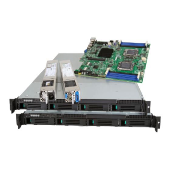
The contents of the server system are listed below. ® Intel Server System SR1695WB - Product Contents ® Your Intel Server System SR1695WB ships with the following items: ® • Intel Server Board S5500WB, installed in the server system •... - Page 5 RAID controller add-in card • Operating system • For information about which accessories, memory, processors, and third-party hardware were tested and can be used with your board, and for ordering information for Intel products, see http://support.intel.com/support/motherboards/server/S5500WB/compat.htm ® Intel Server System SR1695WB Service Guide...
- Page 6 ® Intel Server System SR1695WB Service Guide...
-
Page 7: Safety Information
Safety Information Important Safety Instructions Read all caution and safety statements in this document before performing any of the instructions. See also Intel Server Boards and Server Chassis Safety Information on the ® Intel Server Deployment Toolkit CD and/or at http://support.intel.com/support/motherboards/server/sb/cs-010770.htm. -
Page 8: Warnings
Take care to grip with, but not squeeze, the pliers or other tool you use to remove a jumper, or you may bend or break the pins on the board. ® viii Intel Server System SR1695WB Service Guide... -
Page 9: Table Of Contents
About this Manual ......................... iii Manual Organization ......................iii Product Contents ........................iv ® Intel Server System SR1695WB - Product Contents ..........iv Safety Information ....................vii Important Safety Instructions ....................vii Wichtige Sicherheitshinweise ....................vii Consignes de sécurité ......................vii Instrucciones de seguridad importantes ................ - Page 10 Removing the I/O Expansion Module(s) ..............49 ® ® Installing and Removing the Intel Remote Management Module 3 and the Intel RMM 3 NIC Installing the Intel® RMM3 and Intel® RMM3 NIC ............50 ® ® Removing the Intel RMM3 and Intel RMM3 NIC ............. 51 Replacing the Backplane Board ..................
- Page 11 Industry Canada (ICES-003) ..................90 Europe (CE Declaration of Conformity) ...............91 VCCI (Japan) .......................91 BSMI (Taiwan) ......................91 KCC (Korea) ........................92 Rack Mount Installation Guidelines ................92 Power Cord Usage Guidelines ..................93 Product Ecology Compliance ..................94 ® Intel Server System SR1695WB Service Guide...
- Page 12 Pratiques de manipulation de l’équipement .............. 120 Alimentation et avertissements en matiére d’électricité ..........120 Avertissements sur le cordon d’alimentation ............. 121 Avertissements sur l’accés au systéme ..............121 Avertissements sur le montage en rack ..............122 ® Intel Server System SR1695WB Service Guide...
- Page 13 Advertencias de alimentacién y eléctricas ..............126 Advertencias sobre el cable de alimentación ............126 Advertencias el acceso al sistema ................127 Advertencias sobre el montaje en bastidor ...............128 Descarga electrostática (ESD) ..................129 Otros riesgos ......................129 简体中文 ..........................131 ® Intel Server System SR1695WB Service Guide xiii...
- Page 14 ® Intel Server System SR1695WB Service Guide...
- Page 15 Figure 5. Configuration Jumper Location ................11 Figure 6. Light Guided Diagnostic LEDs ................. 13 Figure 7. Back Panel Connectors.................... 14 ® Figure 8. Front Control Panel - Intel Server System SR1695WB.......... 16 Figure 9. Server System I/O Connector Locations..............18 Figure 10. Optional Peripherals....................19 Figure 11.
- Page 16 Figure 49. Installing the Rack Handle ..................59 Figure 50. Removing the Rack Handle ................... 60 Figure 51. CMOS Recovery Jumper..................65 Figure 52. Password Recovery Jumper.................. 66 Figure 53. Diagnostic LED Placement Diagram ..............73 ® Intel Server System SR1695WB Service Guide...
- Page 17 Server System SR1695WB Feature Summary ..........3 Table 3. NIC LED Descriptions ....................14 Table 4. Control Panel LED Functions ..................16 Table 5. List of Supported I/O Modules on SR1695WB ............23 Table 6. Setup Menu Key Use ....................62 Table 7. 450-W Power Supply Output Voltages ..............67 Table 8.
- Page 18 ® xviii Intel Server System SR1695WB Service Guide...
-
Page 19: Chapter 1: Server System References
® If you just received this Intel Server System SR1695WB Quick Start User's Guide in the product and need to product box install it Accessories or other Intel Spares/Parts List and Configuration Guide can be found at: server products http://support.intel.com/support/motherboards/server/S5500WB/... - Page 20 Firmware Update can be found at: updates http://support.intel.com/support/motherboards/server/S5500WB/ For diagnostics test Diagnostics: Platform Confidence Test (PCT) software Found at: http://support.intel.com/support/motherboards/server/S5500WB/ ® and available on the Intel Server Deployment Toolkit CD that ships with your system. ® Intel Server System SR1695WB Service Guide...
-
Page 21: Chapter 2: Server System Features
Server System Features ® This chapter briefly describes the main features of the Intel Server System SR1695WB. This chapter provides illustrations of the product, a list of the server system features, and diagrams showing the location of important components and connections on the server system. - Page 22 FC-LGA 1366 Socket B package with up to 95 W Thermal Design Power (TDP). • Supports future processor compatibility guidelines ® 4.8 GT/s, 5.86 GT/s, and 6.4 GT/s Intel Quick Path Interconnect ® (Intel QPI). Meets EVRD11.1 Memory Capacity Expandable to 64 GB maximum.
- Page 23 ® Table 2. Intel Server System SR1695WB Feature Summary Feature Description On-board Video On-board Server Engines* LLC Pilot II Controller Matrox* G200 2D Video Graphics controller Uses 8 MB of the BMC 32 MB DDR2 Memory ® ® LAN Support...
-
Page 24: Cable Routing
Use caution to make sure no cables or wires are pinched and that the airflow from the fans is not blocked. Use the following figures to determine the correct cable routing for the SR1695WB system. RAID Module... -
Page 25: Chassis Component Identification
Hot swap backplane 450W power supply unit System Fans (CPU fans and Memory fans) J. Optional slimline optical drive Air Duct Hot swap HDD carrier PCI Express* add-in card bracket Figure 3. System Components ® Intel Server System SR1695WB Service Guide... -
Page 26: Server Board Connector And Component Locations
PCI Express* x16 Gen2 Processor Socket 2 Remote Management Module 3 4-pin Fan Connector (CPU2) POST Code LEDs 4-pin Fan Connector (CPU2A) External I/O 4-pin Fan Connector (MEM2) USB Connector 8-pin Fan Connector (MEM2R) ® Intel Server System SR1695WB Service Guide... -
Page 27: Figure 4. Server Board Connector And Component Locations
4-pin Fan Connector (MEM1) SGPIO Connector 4-pin Fan Connector (CPU1A) IPMB Connector 4-pin Fan Connector (CPU1) Serial Port B HDD Power Connector Processor Socket 1 Figure 4. Server Board Connector and Component Locations ® Intel Server System SR1695WB Service Guide... -
Page 28: Configuration Jumpers
DCD to DTR Internal External ME BMC Update J7A2 DSR to DTR BMC Force Update J1B5 Normal Update Password Clear J1C2 Normal Clear Password BIOS Recovery Mode J1C3 Normal Recovery J1B4 Normal Reset BIOS AF003454 ® Intel Server System SR1695WB Service Guide... -
Page 29: Figure 5. Configuration Jumper Location
Clear CMOS settings Video Internal connector overrides Master(J6A3)e External connector overrides Serial DTR (Data Terminal Ready) mode Interface(J6A2) DCD (Data Carrier Detect) mode None DSR (Data Set Ready) mode Figure 5. Configuration Jumper Location ® Intel Server System SR1695WB Service Guide... -
Page 30: Intel Light Guided Diagnostics
• The Fan Fault LEDs on the server board (see Figure 6) help identify failed and failing fans. The fan fault LEDs turn on (amber) if there is a fan fault. ® Intel Server System SR1695WB Service Guide... -
Page 31: Figure 6. Light Guided Diagnostic Leds
FLT_A2 FLT_B FLT_A1 FLT_C AF003455 Diagnostic LED CPU2 DIMM fault LEDs System Status LED System ID LED 5V Standby LED CPU1 DIMM fault LEDs Fan Fault LEDs Figure 6. Light Guided Diagnostic LEDs ® Intel Server System SR1695WB Service Guide... -
Page 32: Back Panel Connectors
Figure 7. Back Panel Connectors ® Note: The Intel Server System SR1695WB requires the use of shielded LAN cable to comply with Emission/Immunity regulatory requirements. Use of non-shield cables may result in product non-compliance. The NIC LEDs at the right and left of each NIC provide the following information. -
Page 33: Raid Support
To enable RAID 5, this activation key is placed on the SATA Key connector that ® is located at the right side of the server board. For information on how to install the Intel RAID Activation Key AXXRAKSW5 accessory to enable RAID 5, see the documentation that is included with the accessory kit. -
Page 34: Front Panel Of Server System
System NIC 2 Activity LED System Identification LED System Status LED System Identification Button USB 2.0 connectors – Port 0 & 1 ® Figure 8. Front Control Panel - Intel Server System SR1695WB Table 4. Control Panel LED Functions Color State Description... - Page 35 If the system is not powered down normally, it is possible the Power LED will blink at the same time the system status LED is off due to a failure or configuration change that prevents the BIOS from running. ® Intel Server System SR1695WB Service Guide...
-
Page 36: Rear Of Server System
Figure 9. Server System I/O Connector Locations Peripheral Devices The server system provides locations and hardware for installing hard drives and a slimline optical drive. You must purchase the drives separately. The following figure shows the available options. AF003221 ® Intel Server System SR1695WB Service Guide... -
Page 37: Hard Disk Drives
Server System SR1695WB can be mounted into a rack. Intel provides three options to mount this server into a rack. When installing the chassis into a rack, Intel recommends you install systems from the bottom of the rack to the top. In other words, install the first system in the rack into the bottom position of the rack, the second system in the second position from the bottom, and so on. -
Page 38: Hardware Requirements
Server System SR1695WB supports a DDR3-based memory subsystem. The ® Intel Server System SR1695WB supports two DIMMs per channel. The silkscreen on the board for the DIMMs displays DIMM_A1, DIMM_A2, DIMM_B1, DIMM_B2, DIMM_D1, DIMM_D2, DIMM_E1, DIMM_E2. See Figure 11. The minimal memory population possible is DIMM_A1. -
Page 39: Memory Sparing And Mirroring
(RAS latency, CAS latency, and so forth). Memory Sparing and Mirroring ® The spare mode is not supported by Intel Server System SR1695WB. With memory mirroring, the system maintains two copies of all data in the memory subsystem. If a DIMM fails, the data is not lost because the second copy of the data is available from the mirrored DIMM in the opposite channel. -
Page 40: Power Supply
Power Supply The AC or DC Power supply in SR1695WB system provides 450W at maximum. The power supply must provide a minimum of 2.6 A of 5V standby current or the board will not boot. -
Page 41: Intel I/O Expansion Module
I/O Expansion Module connectors on the rear of the server board. It accommodates both the double-wide I/O expansion modules and the PCI Express* Gen 1 I/O modules. Below is the list of supported I/O modules on SR1695WB: Table 5. List of Supported I/O Modules on SR1695WB... - Page 42 ® Intel Server System SR1695WB Service Guide...
-
Page 43: Chapter 3: Hardware Installations And Upgrades
1. Remove the top cover screw (see letter “A”). 2. Loosen the screw at the rear of the chassis (see letter “B”). 3. Push rearward on the blue grip point at the front of the server. ® Intel Server System SR1695WB Service Guide... -
Page 44: Installing The System Cover
Slide the cover forward (see letter “A” in Figure 14). 3. Tighten the screw at the rear of the server (see letter “B”) and install the two screws at the front of the server (see letter “C”). ® Intel Server System SR1695WB Service Guide... -
Page 45: Removing And Installing The Processor Air Duct
2. Power down the server and unplug all peripheral devices and the power cable. 3. Remove the server system cover. For instructions, see “Removing the System Cover”. 4. Lift the processor air duct from its location behind the two system blower fans. ® Intel Server System SR1695WB Service Guide... -
Page 46: Installing The Processor Air Duct
4. Lower the air duct into place; align the air duct side walls to the corresponding slots on the bracket behind the four system blower fans and insert into position. Use caution not to pinch or disengage cables that may be near or under the air duct. ® Intel Server System SR1695WB Service Guide... -
Page 47: Installing And Removing Memory
2. Turn off all peripheral devices connected to the server. 3. Turn off the server. 4. Disconnect the power cord from the server. 5. Remove the cover from the server and locate the DIMM sockets (see Figure 17). ® Intel Server System SR1695WB Service Guide... -
Page 48: Removing Dimms
5. Gently spread the retaining clips at each end of the socket. The DIMM lifts from the socket. 6. Holding the DIMM by the edges, lift it from the socket, and store it in an anti-static package. ® Intel Server System SR1695WB Service Guide... -
Page 49: Installing Or Replacing The Processor
5. Locate the processor socket and open the socket lever (see Figure 18). AF003228 Figure 18. Lifting the Load Lever 6. Open the load plate (see letter “A” in Figure 18 and letter “B” in Figure 18). ® Intel Server System SR1695WB Service Guide... -
Page 50: Figure 19. Open The Load Plate
Figure 19. Open the Load Plate 7. Remove the socket protective cover (see Figure 19). 8. Take the processor out of the box and remove the protective shipping cover (Figure 20). AF003292 Figure 20. Removing the socket ® Intel Server System SR1695WB Service Guide... -
Page 51: Figure 21. Aligning The Processor
Figure 22. Close the Load Plate and Socket Lever Note: Make sure the alignment triangle mark and the alignment triangle cutout align correctly. To assist in package orientation and alignment with the socket: ® Intel Server System SR1695WB Service Guide... -
Page 52: Installing The Heat Sink(S)
Replacing a Processor 1. Observe the safety and ESD precautions at the beginning of this book. 2. Turn off all peripheral devices connected to the server. Turn off the server. ® Intel Server System SR1695WB Service Guide... -
Page 53: Installing And Removing A Hot-Swap Hard Drive
Installing and Removing a Hot-swap Hard Drive ® You can install up to two fixed SATA drives in the Intel Server System SR16WB90 Service Guide. See “Server System References”... -
Page 54: Figure 24. Pulling Out The Back Lever
6. Align the holes in the drive to the holes in the drive carrier and attach it to the carrier with the screws that were attached to the drive blank. AF003303 Figure 25. 2.5 HDD Installation ® Intel Server System SR1695WB Service Guide... -
Page 55: Figure 26. 3.5 Hdd Installation
Do not push on the black drive carrier lever until the lever begins to close by itself. 8. When the black drive carrier lever begins to close by itself, push on it to lock the drive assembly into place. AF003305 Figure 27. Locking the drive assembly ® Intel Server System SR1695WB Service Guide... -
Page 56: Removing A Sas Or Sata Hot-Swap Hard Disk Drive
To maintain proper system cooling, if you do not install a device at this location, you must install the provided filler blank. Installing a Slimline Optical Drive 1. Remove the slimline drive bay filler blank, if installed. ® Intel Server System SR1695WB Service Guide... -
Page 57: Figure 28. Removing The Knockout In Bezel For Optical Opening
3. Screw the latch to the optical drive, and plug in the composed SATA/SATA Power cable, which is shipped in system package. AF003312 Figure 29. Attaching the Brackets to the Optical Drive 4. Lead the SATA/SATA Power cable through the optical drive bay before inserting the drive. ® Intel Server System SR1695WB Service Guide... -
Page 58: Figure 30. Installing The Optical Drive Into The Server System
6. Connect the SATA cable connector to SATA port 4 or 5 on server board. 7. Connect the SATA power connector to P6 connector from system power supply. AF003462 Figure 30. Installing the Optical Drive into the Server System ® Intel Server System SR1695WB Service Guide... -
Page 59: Removing A Slimline Optical Drive
1. Lower the riser assembly into place (see letter “A”). 2. Align the two hooks in the riser assembly with the matching slots at the back of the server system (see letter “B”). ® Intel Server System SR1695WB Service Guide... -
Page 60: Installing And Removing A Pci Add-In Card
PCI bracket shield to the rear of the chassis to remove the shield. Retain the screw. 2. Insert the PCI card edge connector in the slot on the PCI riser. ® Intel Server System SR1695WB Service Guide... -
Page 61: Removing A Pci Add-In Card
1. Remove the screw holding the add-in card in place (see letter “A”). 2. Remove the PCI add-in card from the riser card connector (see letter “B”). AF003325 Figure 34. Removing a PCI Card in a Riser Card ® Intel Server System SR1695WB Service Guide... -
Page 62: Removing And Installing The System Fans
If a fan in the power supply fails, you must replace the power supply. Use the following steps to replace a system fan. Replacing the System Fans 1. Remove the processor air duct. For instructions, see “Removing the Processor Air Duct”. ® Intel Server System SR1695WB Service Guide... -
Page 63: Figure 35. Replacing The System Fans
2. Disconnect the two 4-pin or one 8-pin system fan cables from the server board. See letters “2” in the following figure. 3. Lift the failed fan from the module. 4. Remove the plastic screws from the failed fans and install them into the new fans. ® Intel Server System SR1695WB Service Guide... -
Page 64: Figure 36. Remove The Screws From The Fans
6. With the fan oriented correctly, insert the fan into the fan module (see letter “3”), and insert the fan cable into the matching connector on the server board. (see letter “2”). ® Intel Server System SR1695WB Service Guide... -
Page 65: Installing And Removing The I/O Expansion Module(S)
Installing and Removing the I/O Expansion Module(s) Installing the I/O Expansion Module(s) 1. Squeeze the sides of the I/O expansion module cover to disengage it from the server system back panel and remove it (see letter “A”). ® Intel Server System SR1695WB Service Guide... -
Page 66: Figure 38. Installing The I/O Expansion Module(S)
2. Attach the standoffs to the server board (see letter “A”) and attach the I/O shield gasket to the module (see letter “B”). 3. Attach the I/O expansion module(s) to the server board (see letter “C”). ® Intel Server System SR1695WB Service Guide... -
Page 67: Removing The I/O Expansion Module(S)
1. Remove the I/O expansion module(s) from the server board (see letter “A”). 2. Remove the standoffs from the server board (see letter “B”). 3. Install the I/O expansion module cover into the system back panel (see letter “C”). ® Intel Server System SR1695WB Service Guide... -
Page 68: Rmm 3 Nic
Remote ® Management Module 3 and the Intel RMM 3 NIC Installing the Intel® RMM3 and Intel® RMM3 NIC ® 1. Squeeze the sides of the Intel RMM3 NIC module cover to disengage it from the server system back panel and remove it (see letter “A”) AF003469 ®... -
Page 69: Removing The Intel ® Rmm3 And Intel ® Rmm3 Nic
RMM3 NIC ® Use the reverse steps to remove the Intel RMM3 module ® 1. Remove the two screws from rear chassis to loosen Intel RMM3 board (see letter “C”). ® 2. Plug out Intel RMM3 NIC module cable from the server board (see letter “B”). -
Page 70: Removing The Backplane Board
2. Tighten two screws to lock the backplane assembly in position (see letter “B”). 3. Connect data/power cables to the backplane connectors. 4. Engage hard drives back to the backplane (see letter “C”). ® Intel Server System SR1695WB Service Guide... -
Page 71: Replacing The Server Board
4. If installed, disconnect all SATA cables from the server board. 5. Disconnect the system fans cables from server board. 6. Disconnect all power cables coming from the power supply to the server board. ® Intel Server System SR1695WB Service Guide... -
Page 72: Installing The Server Board
Installing the Server Board 1. Place the server board into the server system as shown in the following figure (see letter “A”). 2. Attach the server board with nine screws (see letter “B”). ® Intel Server System SR1695WB Service Guide... -
Page 73: Figure 45. Installing The Server Board
4. Re-connect the system fan cables to server board. 5. Re-connect all SATA cables to the server board. 6. Install the PCI riser assembly. 7. Install the memory, processor heat sinks, and processors. 8. Install the system air duct. ® Intel Server System SR1695WB Service Guide... -
Page 74: Replacing The Backup Battery
Varning: Explosionsfara vid felaktigt batteribyte. Använd samma batterityp eller en ekvivalent typ som rekommenderas av apparattillverkaren. Kassera använt batteri enligt fabrikantens instruktion. Varoitus: Paristo voi räjähtää, jos se on virheellisesti asennettu. Vaihda paristo ainoastaan laitevalmistajan suosittelemaan tyyppiin. Hävitä käytetty paristo valmistajan ohjeiden mukaisesti. ® Intel Server System SR1695WB Service Guide... -
Page 75: Replacing The Power Supply
Removing the Power Supply You can replace the power supply if it fails or if one of the fans integrated into it fails. To replace the power supply, use the following instructions. ® Intel Server System SR1695WB Service Guide... -
Page 76: Installing The Power Supply
3. Pull the handle to pull out the power supply module (see letter “C”). Installing the Power Supply 1. Insert the replacement power supply module into the power supply cage and push hard until it clicks into place (see letter “A”). ® Intel Server System SR1695WB Service Guide... -
Page 77: Installing And Removing The Rack Handles
1. Align the rack handle with the holes on the side of the server system and attach the rack handle with the three screws. AF003326 Figure 49. Installing the Rack Handle 2. Repeat step 1 on the opposite side of the server. ® Intel Server System SR1695WB Service Guide... -
Page 78: Removing The Rack Handles
Removing the Rack Handles 1. Remove the three screws holding the rack handle in place, and remove the rack handle from the server system. AF003327 Figure 50. Removing the Rack Handle ® Intel Server System SR1695WB Service Guide... -
Page 79: Chapter 4: Server Utilities
You can run the BIOS Setup with or without an operating system ® being present. See “Server System References” for a link to the Intel Server Board S5500WB Technical Product Specification where you can find details about specific BIOS setup screens. -
Page 80: Table 6. Setup Menu Key Use
If “No” is selected and the <Enter> key is pressed, or if <Esc> is pressed, the user is returned to where they were before <F9> was pressed without affecting any existing field values. ® Intel Server System SR1695WB Service Guide... -
Page 81: Upgrading The Bios
Press <F2> Key if you want to run SETUP 2. Write down the current settings in the BIOS Setup program. Note: Do not skip step 2. You need these settings to configure your server at the end of the procedure. ® Intel Server System SR1695WB Service Guide... -
Page 82: Upgrading The Bios
1. Power down the system; do not disconnect the power. 2. Open the server. 3. Move the jumper from the normal operation position, at pins 1 and 2 to the CMOS Clear Force Erase position, covering pins 2 and 3. ® Intel Server System SR1695WB Service Guide... -
Page 83: Resetting The Password
2. Open the server chassis. 3. Move the jumper from the normal operation position, Password Clear Protect, at pins 1 and 2 to the Password Clear Erase position, covering pins 2 and 3. ® Intel Server System SR1695WB Service Guide... -
Page 84: Figure 52. Password Recovery Jumper
7. The password is now cleared and you can reset it by going into the BIOS setup. CMOS Clear J1B4 1-2: Default 2-3: Clear CMOS BMC Force Update J1B5 1-2: Default 2-3: Enabled Password Clear J1C2 1-2: Default 2-3: Password Clear AF003214 Figure 52. Password Recovery Jumper ® Intel Server System SR1695WB Service Guide... -
Page 85: Appendix A: Technical Reference
2. Peak load on the combined 12V output shall not exceed 40A peak. 3. Maximum continuous load on the combined 12V output shall not exceed 37A. 4. Peak power and peak current loading shall be supported for a minimum of 12 seconds. ® Intel Server System SR1695WB Service Guide... -
Page 86: System Environmental Specifications
(23 +/- degrees C) Sound Power: 7.0 BA in an idle state at typical office ambient temperature. (23 +/- 2 degrees C). Electrostatic +/-12 kV except I/O port +/-8 KV, per Intel Environmental Test Specification. discharge (ESD)* ®... -
Page 87: Appendix B: Intel ® Server Issue Report Form
Board / Chassis Information Baseboard Revision - PBA#: _____________________________________________ Baseboard Serial Number: _______________________________________________ CPU1 Speed/Stepping/Spec: _____________________________________________ CPU2 Speed/Stepping/Spec: _____________________________________________ System BIOS Version: __________________________________________________ HSC Firmware Version: _________________________________________________ Chassis Model: ________________________________________________________ ® Intel Server System SR1695WB: __________________________________ ® Intel Server System SR1695WB Service Guide... - Page 88 DIMM D2 MB and Vendor / part number: __________________________________ DIMM E1 MB and Vendor / part number: __________________________________ DIMM F1 MB and Vendor / part number: __________________________________ Operating System Information Operating System:_____________________________________________________ Version: _____________________________________________________________ Service Pack:_________________________________________________________ ® Intel Server System SR1695WB Service Guide...
- Page 89 Intel Expansion Module Revision #NIC Hard Drive Information Drive Type (SATA/ Make/Model Revision SAS) SATA_0 SATA_1 SATA_2 SATA_3 SATA_4 SATA_5 Management Information On-Board Platform Instrumentation only ___________________________________ ® Intel Remote Management Module _______________________________________ ® Intel Server System SR1695WB Service Guide...
- Page 90 Please also include any details on troubleshooting already done. ____________________________________________________________________ ____________________________________________________________________ ____________________________________________________________________ ____________________________________________________________________ ____________________________________________________________________ ____________________________________________________________________ ____________________________________________________________________ ____________________________________________________________________ ____________________________________________________________________ ____________________________________________________________________ ____________________________________________________________________ ____________________________________________________________________ ____________________________________________________________________ ____________________________________________________________________ ____________________________________________________________________ ____________________________________________________________________ ____________________________________________________________________ ____________________________________________________________________ ____________________________________________________________________ ____________________________________________________________________ ____________________________________________________________________ ® Intel Server System SR1695WB Service Guide...
-
Page 91: Appendix C: Led Decoder
The Diagnostic LED #7 is labeled as “MSB”, and the Diagnostic LED #0 is labeled with “LSB”. POST LED 7 POST LED 0 POST LED 6 POST LED 1 POST LED 5 POST LED 2 POST LED 4 POST LED 3 AF003478 Figure 53. Diagnostic LED Placement Diagram ® Intel Server System SR1695WB Service Guide... -
Page 92: Table 9. Post Progress Code Led Example
(including AP) 0x12h Starting application processor initialization 0x13h SMM initialization 0x14h Selection of Processor with least feature use as Boot Strap Processor 0x15h Switch an AP processor to become the new Boot Strap Processor ® Intel Server System SR1695WB Service Guide... - Page 93 DIMM configuration (system halted) 0xEAh DIMM training sequence failed (system halted) 0xEBh Memory test failed (system halted) 0xECh Unsupported or invalid DIMM configuration (system halted) 0xEDh Unsupported or invalid DIMM configuration (system halted) ® Intel Server System SR1695WB Service Guide...
- Page 94 Memory Initialization of Integrated Memory Controller 0xB1h Memory Initialization of Integrated Memory Controller 0xB2h Memory Initialization of Integrated Memory Controller 0xB3h Memory Initialization of Integrated Memory Controller 0xB4h Memory Initialization of Integrated Memory Controller ® Intel Server System SR1695WB Service Guide...
- Page 95 Memory Initialization of Integrated Memory Controller 0xBCh Memory Initialization of Integrated Memory Controller 0xBDh Memory Initialization of Integrated Memory Controller 0xBEh Memory Initialization of Integrated Memory Controller 0xBFh Memory Initialization of Integrated Memory Controller ® Intel Server System SR1695WB Service Guide...
- Page 96 0x5Bh Reserved for ATA SMBUS 0x5Eh Resetting SMBUS 0x5Fh Reserved for SMBUS I/O Controller Hub 0x61h Initializing I/O Controller Super I/O 0x63h Initializing Super I/O Local Console 0x70h Resetting the video controller (VGA) ® Intel Server System SR1695WB Service Guide...
- Page 97 Detecting the presence of mouse 0x9Bh Enabling the mouse 0x9Ch Reserved for mouse Serial Port 0xA8h Resetting the serial port 0xA9h Disabling the serial port 0xAAh Detecting the presence of the serial port ® Intel Server System SR1695WB Service Guide...
- Page 98 0xD0 Entered the Boot Device Selection phase (BDS) 0xD1 Return to last good boot device 0xD2 Set up boot device selection policy 0xD3 Connect boot device controller 0xD4 Attempt flash update boot mode ® Intel Server System SR1695WB Service Guide...
- Page 99 Started dispatching drivers 0xE6h Started connecting drivers DXE Drivers 0xE7h Waiting for user input 0xE8h Checking password 0xE9h Entering BIOS setup 0xEAh Flash Update 0xEBh Legacy Option ROM Initialization 0xECh DXE Drivers initialized ® Intel Server System SR1695WB Service Guide...
- Page 100 Loading crisis recovery capsule 0x35h Handing off control to the crisis recovery capsule 0x36h Begin crisis recovery 0x3Eh No crisis recovery capsule detected 0x3Fh Crisis recovery capsule failed integrity check of capsule descriptors ® Intel Server System SR1695WB Service Guide...
-
Page 101: Appendix D: Getting Help
— A searchable knowledge base to search for product information throughout the support site 2. If you are still unable to obtain a solution to your issue, send an e-mail to Intel’s technical support center using the online form available at http://supportmail.intel.com/scripts-emf/welcome.aspx... - Page 102 ® Intel Server System SR1695WB Service Guide...
-
Page 103: Appendix E: Regulatory And Compliance Information
(or higher) and operating at the same (or higher) speed as the microprocessor used on this server board. The final configuration of your end system product may require additional EMC compliance testing. For more information, please contact your local Intel representative. -
Page 104: Product Emc Compliance - Class A Compliance
Product EMC Compliance - Class A Compliance Note: Legally the product is required to comply with Class A emission requirements as it is intended for a commercial type market place. Intel targets 10db margin to Class A Limits ® The Intel... -
Page 105: Product Regulatory Compliance References
Note: Certifications Emissions requirements are to Class A. Table 11. Product Regulatory Compliance References Compliance Compliance Compliance Reference Marking Regional Reference Example Description Australia / New AS/NZS CISPR22 (Emissions) Zealand N232 Argentina IRAM Certification (Safety) ® Intel Server System SR1695WB Service Guide... - Page 106 EMC Directive 2004/108/E EN55022 (Emissions) EN55024 (Immunity) EN61000-3-2 (Harmonics) EN61000-3-3 (Voltage Flicker) CE Declaration of Conformity Germany GS Certification – EN60950-1 International CB Certification – IEC60950-1 None Required CISPR 22 / CISPR 24 Japan VCCI Certification ® Intel Server System SR1695WB Service Guide...
-
Page 107: Electromagnetic Compatibility Notices
(1) this device may not cause harmful interference, and (2) this device must accept any interference received, including interference that may cause undesired operation. For questions related to the EMC performance of this product, contact: Intel Corporation 5200 N.E. Elam Young Parkway ® Intel Server System SR1695WB Service Guide... -
Page 108: Industry Canada (Ices-003)
This digital apparatus does not exceed the Class A limits for radio noise emissions from digital apparatus set out in the interference-causing equipment standard entitled: "Digital Apparatus," ICES-003 of the Canadian Department of Communications. ® Intel Server System SR1695WB Service Guide... -
Page 109: Europe (Ce Declaration Of Conformity)
(pedestal orientation) or side (rack mount configuration). The BSMI Certification Marking and EMC warning is located on the outside rear area of the product. ® Intel Server System SR1695WB Service Guide... -
Page 110: Kcc (Korea)
AC outlet that is part of the rack, then you must provide proper grounding for the rack itself. If the server power cord is plugged into a wall AC ® Intel Server System SR1695WB Service Guide... -
Page 111: Power Cord Usage Guidelines
(American Wire Gauge). Outside of the U.S. and Canada, cords must be flexible harmonized (<HAR>) or VDE (Verband Deutscher Electrotechniker, German Institute of Electrical Engineers) certified cord with 3 x 0.75 mm conductors rated 250 VAC (Volts Alternating Current). ® Intel Server System SR1695WB Service Guide... -
Page 112: Product Ecology Compliance
Cord length and flexibility: Cords must be less than 4.5 meters (14.76 feet) long. Product Ecology Compliance Intel has a system in place to restrict the use of banned substances in accordance with world wide product ecology regulatory requirements. The following is Intel's product ecology compliance criteria. - Page 113 Intel’s Environmental Product Content Specification of Suppliers and Outsourced Manufacturers – http:// supplier.intel.com/ehs/ environmental.htm International ISO11469 - >PC/ABS< Plastic parts weighing >25gm are intended to be marked with per ISO11469. ® Intel Server System SR1695WB Service Guide...
- Page 114 Table 12. Product Ecology Compliance Compliance Regional Compliance Reference Marking Compliance Reference Description Example Recycling Markings – Fiberboard (FB) and Cardboard (CB) are marked with international recycling marks. Applied to outer bulk packaging and single package. ® Intel Server System SR1695WB Service Guide...
-
Page 115: Other Markings
为避免遭受电击, 在进行维修之前应断开两 (2)条电源系统电缆。 Traditional Chinese: 注意: 本設備包括多條電源系統電纜。 為避免遭受電擊, 在進行維修之前應斷開兩 (2)條電源系統電纜。 German: Dieses Geräte hat mehr als ein Stromkabel. Um eine Gefahr des elektrischen Schlages zu verringern trennen sie beide (2) Stromkabeln bevor Instandhaltung. ® Intel Server System SR1695WB Service Guide... -
Page 116: Regulated Specified Components
Updated product information for configurations can be found on the Intel Server Builder Web site at the following URL: http://channel.intel.com/go/serverbuilder If you do not have access to Intel's Web address, please contact your local Intel representative. • Server Chassis: (base chassis is provided with power supply and fans) - NRTL listed. -
Page 117: End-Of-Life / Product Recycling
End-of-Life / Product Recycling Product recycling and end-of-life take-back systems and requirements vary by country. Contact the retailer or distributor of this product for information about product recycling and / or take-back. ® Intel Server System SR1695WB Service Guide... - Page 118 ® Intel Server System SR1695WB Service Guide...
-
Page 119: Appendix F: Warranty
“as is” unless specifically provided for otherwise in any software license accompanying the software. If any Product furnished by Intel which is the subject of this Limited Warranty fails during the warranty period for reasons covered by this Limited Warranty, Intel, at its option, will: •... -
Page 120: Limitations Of Liability
Limitations of Liability Intel's responsibility under this, or any other warranty, implied or expressed, is limited to repair, replacement, or refund, as set forth above. These remedies are the sole and exclusive remedies for any breach of warranty. - Page 121 Telephone Support If you cannot find the information you need on Intel's World Wide Web site (http:// www.intel.com/), call your local distributor or an Intel Customer Support representative.
- Page 122 ® Intel Server System SR1695WB Service Guide...
-
Page 123: Appendix G: Installation/Assembly Safety Instructions
Appendix G: Installation/Assembly Safety Instructions Important Safety Instructions Read all caution and safety statements in this document before performing any of the instructions. See also Intel Server Boards and Server Chassis Safety Information on the Resource CD and/or at: http://support.intel.com/support/motherboards/server/sb/cs-010770.htm English... -
Page 124: Wichtige Sicherheitshinweise
Wichtige Sicherheitshinweise Lesen Sie zunächst sämtliche Warn- und Sicherheitshinweise in diesem Dokument, bevor Sie eine der Anweisungen ausführen. Beachten Sie hierzu auch die Sicherheitshinweise zu Intel-Serverplatinen und -Servergehäusen auf der Ressourcen-CD oder unter: http://support.intel.com/support/motherboards/server/sb/cs-010770.htm SICHERHEISMASSNAHMEN: Immer wenn Sie die Gehäuseabdeckung abnehmen um an das Systeminnere zu gelangen, sollten Sie folgende Schritte beachten: 1. -
Page 125: Consignes De Sécurité
Lisez attention toutes les consignes de sécurité et les mises en garde indiquées dans ce document avant de suivre toute instruction. Consultez Intel Server Boards and Server Chassis Safety Information sur le CD Resource CD ou bien rendez-vous sur le site: http://support.intel.com/support/motherboards/server/sb/cs-010770.htm... - Page 126 Instrucciones de seguridad importantes Lea todas las declaraciones de seguridad y precaución de este documento antes de realizar cualquiera de las instrucciones. Vea Intel Server Boards and Server Chassis Safety Information en el CD Resource y/o en: http://support.intel.com/support/motherboards/server/sb/cs-010770.htm INSTRUCCIONES DE SEGURIDAD: Cuando extraiga la tapa del...
-
Page 127: Italiano
Se il sistema è stato a lungo in funzione, il microprocessore e il dissipatore di calore potrebbero essere surriscaldati. Fare attenzione alla presenza di piedini appuntiti e parti taglienti sulle schede e sul telaio. È consigliabile l'uso di guanti di protezione. ® Intel Server System SR1695WB Service Guide... - Page 128 ® Intel Server System SR1695WB Service Guide...
-
Page 129: Appendix H: Safety Information
To reduce the risk of bodily injury, electrical shock, fire, and equipment damage, read this document and observe all warnings and precautions in ® this guide before installing or maintaining your Intel Server Product. In the event of a conflict between the information in this document and information provided with the product or on the website for a particular product, the product documentation takes precedence. -
Page 130: Intended Application Uses
Conform to local occupational health and safety requirements when moving and lifting equipment. • Use mechanical assistance or other suitable assistance when moving and lifting equipment. • To reduce the weight for easier handling, remove any easily detachable components. ® Intel Server System SR1695WB Service Guide... -
Page 131: Deutsch
Deutsch Sicherheitshinweise für den Server ® ® Das vorliegende Dokument bezieht sich auf Intel Serverplatinen, Intel Servergehäuse (Standfuß und Rack) sowie installierte Peripheriegeräte. Es enthält Warnungen und Vorsichtsmaßnahmen zur Vermeidung von Gefahren durch Verletzung, Stromschlag, Feuer und Beschädigungen von Geräten. Lesen Sie diese Dokument daher sorgfältig, ®... -
Page 132: Zielbenutzer Der Anwendung
Verwenden Sie mechanische oder andere geeignete Hilfsmittel zum Transportieren oder Anheben von Geräten. • Entfernen Sie alle Komponenten, die sich leicht abnehmen lassen, um das Gewicht zu reduzieren und die Handhabung zu erleichtern. ® Intel Server System SR1695WB Service Guide... -
Page 133: Warnungen Zu Netzspannung Und Elektrizität
Typ entspricht. Jedes Netzteil im System muß über ein eigenes Netzkabel angeschlossen werden. Einige Netzteile von Intel Servern verwenden Nullleitersicherungen. Vorsicht ist geboten im Umgang mit Netzteilen, welche Nullleitersicherungen verwenden, um das Risiko eines elektrischen Schlages zu vermeiden Das Netzteil in diesem Produkt enthält keine Teile, die vom Benutzer gewartet werden... -
Page 134: Warnhinweise Für Den Systemzugang
Gehen Sie bei der Installation von Geräten im Rack immer von unten nach oben vor, und bauen Sie das schwerste Gerät an der untersten Position im Rack ein. Ziehen Sie jeweils immer nur ein Gerät aus dem Rack heraus. ® Intel Server System SR1695WB Service Guide... -
Page 135: Elektrostatische Entladungen (Esd)
Inbetriebnahme des Systems ohne Abdeckung kann zur Beschädigung von Systemkomponenten führen. So bringen Sie die Abdeckung wieder an: • Vergewissern Sie sich zunächst, daß Sie keine Werkzeuge oder Teile im Gehäuse vergessen haben. ® Intel Server System SR1695WB Service Guide... -
Page 136: Français
® d’installer ou de mettre à jour votre produit serveur Intel En cas de conflit entre les informations fournies dans ce document et celles livrées avec le produit ou publiées sur le site Web pour un produit particulier, la documentation du produit prime. -
Page 137: Domaines D'utilisation Prévus
Bien ventilé et à l’écart des sources de chaleur telles que la lumière directe du soleil et les radiateurs. • À l’écart des sources de vibration ou des chocs physiques. • Isolé des champs électromagnétiques importants produits par des appareils électriques. ® Intel Server System SR1695WB Service Guide... -
Page 138: Pratiques De Manipulation De L'équipement
Vous devez les débrancher avant d’ouvrir le châssis, d’ajouter ou de supprimer un composant non connectable à chaud. Les alimentations de certains serveurs Intel sont munies de doubles fusibles pôle/neutre: veuillez observer les précautions d'usage afin d'éviter tout risque d'eléctrocution. -
Page 139: Avertissements Sur Le Cordon D'alimentation
Éteignez le système en appuyant sur le bouton d’alimentation. • Déconnectez l’alimentation secteur en débranchant tous les cordons d’alimentation secteur du système ou de la prise murale. • Déconnectez l’ensemble des câbles et lignes de télécommunication qui sont connectés au système. ® Intel Server System SR1695WB Service Guide... -
Page 140: Avertissements Sur Le Montage En Rack
étiqueté comme contrôlant toute l’unité, et pas uniquement le ou les serveurs. Pour éviter tout risque d’électrocution, le rack et chaque élément de l’équipement installé dans le rack doivent être correctement reliés à la terre. ® Intel Server System SR1695WB Service Guide... -
Page 141: Décharges Électrostatiques (Esd)
Vérifiez tout d’abord que vous n’avez pas oublié d’outils ou de composants détachés à l’intérieur du système. • Vérifiez que les câbles, les cartes d’extension et les autres composants sont correctement installés. • Fixez les panneaux au châssis en suivant les instructions du produit. ® Intel Server System SR1695WB Service Guide... -
Page 142: Périphériques Laser
Retournez-les au fabricant en cas de problème. Español Información de seguridad del servidor ® Este documento se aplica a las tarjetas de servidor de Intel , las carcasas de servidor de ® Intel (montaje en bastidor y en pedestal) y los dispositivos periféricos. Para reducir el riesgo de daños corporales, descargas eléctricas, fuego y en el equipo, lea este documento... -
Page 143: Aplicaciones Y Usos Previstos
Provista de una toma de corriente alterna correctamente conectada a tierra. • Provista de espacio suficiente para acceder a los cables de la fuente de alimentación ya que constituyen la desconexión principal de la alimentación. ® Intel Server System SR1695WB Service Guide... -
Page 144: Manipulacién Del Equipo
CA estén desenchufado antes de abrir la carcasa, agregar o extraer cualquier componente que no es de conexión en funcionamiento. Algunas fuentes de alimentación de electricidad de los servidores de Intel utilizan el polo neutral del fuselaje. Para evitar riesgos de choques electricos use precauciónes al trabajar con las fuentes de alimentación que utilizan el polo neutral de fuselaje. -
Page 145: Advertencias El Acceso Al Sistema
Devuélvala al fabricante para repararla. • Apague el servidor y desconecte todos los cables de alimentación antes de agregar o reemplazar cualquier componente que no es de conexión en funcionamiento. ® Intel Server System SR1695WB Service Guide... -
Page 146: Advertencias Sobre El Montaje En Bastidor
Para evitar el riesgo de descargas eléctricas, deberá instalar una conexión a tierra apropiada para el bastidor y para cada pieza del equipo instalada en el mismo. ® Intel Server System SR1695WB Service Guide... -
Page 147: Descarga Electrostática (Esd)
Deseche las baterías respetando la normativa local. No intente recargar la batería. No intente desmontar, pinchar o causar cualquier otro desperfecto a una batería. ® Intel Server System SR1695WB Service Guide... - Page 148 Precaución Para evitar el riesgo de la exposición a radiaciones o de daños personales: • No abra la caja de ningún periférico o dispositivo láser • Los periféricos o dispositivos láser no pueden ser reparados por el usuario • Haga que el fabricante los repare ® Intel Server System SR1695WB Service Guide...
-
Page 149: 简体中文
服 务器 机箱 (基 座和 机架 固定 件) 和已 安装 的外 设。 为减 少人 身伤 害、 电 击、 火灾 以及 设备 毁坏 的危 险, 请在 安装 或维 护 Intel® 服 务器 产品 之前 阅读 本文 档并 遵循 本指 南中 的所 有警 告和 预防 措施 。... - Page 150 • 远离振动源或物理震动。 • 与电气设备产生的强大电磁场隔离。 • 在易受闪电袭击的地区,我们建议将系统插入电涌抑制器并在闪电期间断开通信 线路与调制解调器之间的连接。 • 提供正确接地的墙壁插座。 • 提供足够的空间,以便拿取电源供应线,因为这是本产品的主要电源断开器。 设备操作规范 减少人身伤害或设备受损的危险: • 移举设备时遵守当地的职业健康与安全要求。 • 借助机械手段或其他合适的手段移举设备。 • 拆除一切易分离组件,以降低重量并方便操作。 电源与电气警告 注意事项 电源按钮(如待机电源标记所示)并不能完全关闭系统的交流电源,只要系统已接 通电源,就存在 5V 待机电源。要从系统切断电源,须从墙壁电源插座中拔下交流电线。您的系统可能 不止使用一根交流电线。请确保所有的交流电线都已拔下。打开机箱或增加或去除 任何热插拔组件之前,确保交流电线已拔下。 若非所需的确切类型,请勿尝试修改或使用交流电线。系统的每个电源供应设备都 需要一根单独的交流电线。 本产品的电源供应设备包含非用户维修部件。请勿打开电源供应设备。电源供应设 备包含非常危险的电压级、电流级和能量级。请与生产商联系维修事宜。 替换热插拔电源供应设备时,请先拔下需替换的电源供应设备上的电源线,再将其 从服务器上移除。 ® Intel Server System SR1695WB Service Guide...
- Page 151 ⎯ 电源线须拥有适合插座的安全接地插头或触点。 • 电源线为交流电源的主要断开设备。插座须靠近设备并可随时断开。 • 电源线须插入所提供的拥有合适接地的插座。 系统使用警告 注意事项 为避免人身伤害或财产损失,无论何时检查产品内部,以下安全指导都适用: • 关闭所有与本产品相连的外设。 • 按下电源按钮至关闭状态,关闭系统。 • 从系统或墙壁插座上拔下所有交流电线,断开交流电源。 • 断开与系统相连的所有线缆和通信线路。 • 卸除舱口盖时,保留所有螺钉及其他紧固件。完成产品内部检查之后,请 用螺钉或紧固件重新固定舱口盖。 • 请勿打开电源供应设备。电源供应设备内没有可维修部件。请与生产商联系 维修事宜. • 增加或替换任何非热插拔组件之前,请关闭服务器电源并断开所有电源线 。 • 替换热插拔电源供应设备时,请先拔下需替换的电源供应设备上的电源线 ,然后再从服务器上移除电源供应设备。 注意事项 如果服务器一直在运行,任何已安装的处理器和吸热设备都可能很热。除非要增加 或移除热插拔组件,否则请待系统冷却后再开盖。为避免在热插拔组件安装过程中 接触灼热组件,移除或安装热插拔组件时务须小心。 ® Intel Server System SR1695WB Service Guide...
- Page 152 注意事项 为避免受伤,请勿触摸运转的风机叶片。如果系统的风机上配有防护装置,请勿卸 下风机防护装置运行系统。 机架固定件警告 设备的机架须固定在稳固的支座上,以防从中安装服务器或设备时倒塌。须按照机 架生产商提供的安装说明进行安装。 从下往上将设备安装在机架上,最重的设备安装在机架的最底层。 一次只从机架上安装一件设备。 您须负责安装整个机架装置的主要电源断开设备。此主要断开设备须随时可用,且 须标明为控制整个装置(而不仅限于服务器)的电源。 为避免潜在的电击危险,须对机架及其上所安装的每一件设备实行正确的安全接地 。 静电放电 (ESD) 注意事项 ESD 会损坏磁盘驱动器、主板及其他部件。我们建议您执行 ESD 工作站的所有步骤。如果没有 ESD 工作站,则采取一些静电放电保护措施,操作部件时,戴上与服务器上的机箱接地 或任何未喷漆金属表面连接的防静电腕带。 操作主板时始终保持小心。它们可能对 ESD 非常敏感。拿持主板时只接触边缘。从保护包装中或从服务器上取出主板后,请将 主板组件侧面朝上放置在无静电的接地表面上。请使用导电泡沫垫(若有),不要 使用主板包装。请勿将主板在任何表面上滑动。 ® Intel Server System SR1695WB Service Guide...
- Page 153 其他危险 替换电池 注意事项 不正确替换电池可能导致爆炸危险。替换电池时,请只使用设备生产商推荐使用的 电池。 请按当地法规处置电池。 请勿对电池充电。 请勿拆卸、刺穿或以其他方式损坏电池。 冷却和气流 注意事项 按照说明小心布置线缆,尽量减少气流阻塞和冷却问题。 为保证适当的冷却和气流,运行系统时请确保机箱盖已安装。未安装机箱盖即运行 系统可能导致系统部件受损。安装机箱盖的步骤如下: 首先检查并确保系统内没有遗留的未固定工具或部件。 • 检查线缆、内插板和其他组件已正确安装。 • 按产品说明安装机箱盖。 • 激光外设或激光设备 注意事项 为避免幅射暴露和 / 或人身伤害: 请勿打开任何激光外设或激光设备的外壳 • 激光外设或激光设备为非用户维修设备 • 请与生产商联系维修事宜 ® Intel Server System SR1695WB Service Guide...
- Page 154 ® Intel Server System SR1695WB Service Guide...
Need help?
Do you have a question about the SR1695WB and is the answer not in the manual?
Questions and answers