Intel SR1600UR - Server System - 0 MB RAM Service Manual
Server system
Hide thumbs
Also See for SR1600UR - Server System - 0 MB RAM:
- Service manual (190 pages) ,
- Quick start manual (1 page) ,
- Spares parts list & configuration manual (26 pages)
Table of Contents
Advertisement
Quick Links
Download this manual
See also:
Service Manual
Advertisement
Table of Contents

Related Manuals for Intel SR1600UR - Server System - 0 MB RAM


Summary of Contents for Intel SR1600UR - Server System - 0 MB RAM
- Page 1 ® Intel Server System SR1600UR Service Guide ® A Guide for Technically Qualified Assemblers of Intel Identified Subassemblies/ Products Intel Order Number E52880-005...
- Page 2 Intel products are not designed, intended or authorized for use in any medical, life saving, or life sustaining applications or for any other application in which the failure of the Intel product could create a situation where personal injury or death may occur.
-
Page 3: Preface
Preface About this Manual ® Thank you for purchasing and using the Intel Server System SR1600UR. This manual is written for system technicians who are responsible for troubleshooting, upgrading, and repairing this server system. This document provides reference information, feature information, and step by step instructions on how to add and replace components on the server system. - Page 4 ® Intel Server System SR1600UR Service Guide...
-
Page 5: Safety Information
Safety Information Important Safety Instructions Read all caution and safety statements in this document before performing any of the instructions. See also Intel Server Boards and Server Chassis Safety Information on the ® Intel Server Deployment Toolkit 3.0 CD and/or at http://www.intel.com/support/motherboards/server/sb/cs-010770.htm. - Page 6 重要安全指导 ® Intel Server System SR1600UR Service Guide...
-
Page 7: Warnings
Take care to grip with, but not squeeze, the pliers or other tool you use to remove a jumper, or you may bend or break the pins on the board. ® Intel Server System SR1600UR Service Guide... - Page 8 ® viii Intel Server System SR1600UR Service Guide...
-
Page 9: Table Of Contents
Active Backplane ......................24 Passive Backplane ......................25 RAID Support ........................26 Advanced Management Options ..................26 Intel® Remote Management Module 3 ................26 Rack Mount Options ......................27 Chapter 3: Hardware Installations and Upgrades ..........29 Before You Begin .........................29 Tools and Supplies Needed ..................29 System References .....................29... - Page 10 Removing a Fixed Mount Hard Disk Drive ..............60 Installing and Removing a Hot-swap Hard Drive (Hot-swap Hard Drive System Only) ..61 Installing a Hot-swap SAS or SATA Hard Disk Drive ..........61 ® Intel Server System SR1600UR Service Guide...
- Page 11 Filling Empty Server System Bays ..................67 Installing and Removing the I/O Expansion Module ............68 Installing the I/O Expansion Module ................68 Removing the I/O Expansion Module ................69 ® Installing and Removing the Intel Remote Management Module 3 ........70 ® Installing the Intel RMM3 ...................70 ®...
- Page 12 System Environmental Specifications ................105 ® Appendix B: Intel Server Issue Report Form .............107 Appendix C: LED Decoder ..................113 Appendix D: Getting Help ..................121 Warranty Information ......................121 Appendix E: Regulatory and Certification Information ........123 Product Regulatory Compliance ..................123 Product Safety Compliance ..................
- Page 13 Advertencias de alimentacién y eléctricas ..............165 Advertencias sobre el cable de alimentación ............165 Advertencias el acceso al sistema ................166 Advertencias sobre el montaje en bastidor ...............167 Descarga electrostática (ESD) ..................167 Otros riesgos ......................168 ® Intel Server System SR1600UR Service Guide xiii...
- Page 14 ® Intel Server System SR1600UR Service Guide...
-
Page 15: List Of Figures
Figure 19. Cabling Around the Small Air Baffle (Hot-swap Hard Drive System) ..... 33 Figure 20. Front View with Bezel supporting the Standard Control Panel ......36 ® Figure 21. Front View with Bezel supporting the Intel Local Control Panel ......37 Figure 22. Installing the Front Bezel..................37 Figure 23. - Page 16 Figure 59. Installing the I/O Expansion Module to the Server System........69 Figure 60. Removing the I/O Expansion Module from the Server System ......70 ® Figure 61. Removing the Intel RMM3 filler panel..............71 ® Figure 62. Installing the Intel RMM3 to the bracket ..............
- Page 17 List of Tables Table 1. Server System References ..................3 ® Table 2. Intel Server System SR1600UR Feature Summary ..........6 Table 3. NIC LED Descriptions ....................23 Table 4. Setup Menu Key Use ....................97 Table 5. Power Supply Input Voltages ..................103 Table 6.
- Page 18 ® xviii Intel Server System SR1600UR Service Guide...
-
Page 19: Chapter 1: Server System Contents And References
Server System SR1600UR (fixed mount hard drive system) ® • Intel Server System SR1600URHS (hot-swap hard drive system) ® Unless noted otherwise, all references to the Intel Server System SR1600UR refer to both product codes. Server System Contents ® ®... -
Page 20: Intel Server System Sr1600Urhs Contents
® • Intel System Management Software DVD ® Intel Server System SR1600URHS Contents ® Your Intel Server System SR1600URHS (hot-swap hard drive system) ships with the following items: ® • Intel Server Board S5520UR, installed in the server system •... -
Page 21: Additional Information And Software
Server System SR1600UR Quick Start User's Guide product and you need to Available in the product box assemble your system and install components Accessories or other Intel Spares, Parts List, and Configuration Guide server products Available at: http://www.intel.com/p/en_US/support/highlights/server/s5520ur or by using the Server Configurator Tool Available at: http://serverconfigurator.intel.com/default.aspx... - Page 22 To make sure your system Power Budget Analysis Tool falls within the allowed Available at: power budget http://www.intel.com/p/en_US/support/highlights/server/s5520ur ® For software to manage Intel System Management Software ® your Intel server Available at: http://www.intel.com/go/servermanagement/ ® Intel Server System SR1600UR Service Guide...
-
Page 23: Chapter 2: Server System Features
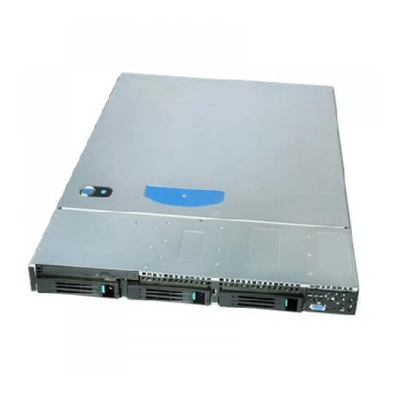
AF002746 ® Figure 1. Intel Server System SR1600UR ® Intel Server System SR1600UR Service Guide... -
Page 24: Server System Feature Overview
Support for one or two Intel Xeon Processors in FC-LGA 1366 Socket B package with up to 95 W Thermal Design Power (TDP) ® • 4.8 GT/s, 5.86 GT/s and 6.4 GT/s Intel QuickPath ® Interconnect (Intel QPI) • EVRD11.1 For a complete list of supported processors, see http://www.intel.com/support/motherboards/server/s5520ur/... - Page 25 • Six Serial ATA (SATA) II connectors • Two I/O module connectors ® • One RMM3 connector to support an optional Intel Remote Management Module 3 • SATA Software RAID 5 Activation Key connector • One SSI-EEB compliant front panel header •...
- Page 26 ® Table 2. Intel Server System SR1600UR Feature Summary Feature Description LEDs and displays LEDs with standard control panel: • NIC1 Activity • NIC2 Activity • Power/Sleep • System Status • System Identification • Hard Drive Activity ® Intel Light-Guided diagnostic LEDs: •...
-
Page 27: Server System Components
Three hot-swap drives supported in hot- swap hard drive system PCI add-in riser assembly Slimline Optical Drive Bay (drive not included) PCI card bracket (full-height) M. Front bezel (optional Processor air duct Figure 2. Server System Components ® Intel Server System SR1600UR Service Guide... -
Page 28: Intel Light-Guided Diagnostics
® Intel Light-Guided Diagnostics The server system contains the following diagnostic LEDs, each providing the following functions: • The System Status LED on the front and back panels (see Figure 3 Figure shows the overall health of the system (green, blinking green, blinking amber, amber, off) . -
Page 29: Figure 3. Intel ® Light-Guided Diagnostic Leds - Server Board
CPU 1 DIMM Fault LEDs CPU 2 Fan Fault LED Memory 2 Fan Fault LED CPU 2 DIMM Fault LEDs 5V Standby LED ® Figure 3. Intel Light-Guided Diagnostic LEDs - Server Board ® Intel Server System SR1600UR Service Guide... -
Page 30: Figure 4. Intel ® Light-Guided Diagnostic Leds - Fan Board
Fan 1 Fault LED Fan 2 Fault LED Fan 3 Fault LED Fan 4 Fault LED Fan 5 Fault LED ® Figure 4. Intel Light-Guided Diagnostic LEDs - Fan Board AF003001 Fan 1 Fault LED Fan 2 Fault LED Fan 3 Fault LED... -
Page 31: Figure 6. Intel Light-Guided Diagnostic Leds - Standard Control Panel
AF003002 Status LED System Identification LED ® Figure 6. Intel Light-Guided Diagnostic LEDs - Standard Control Panel ® Intel Server System SR1600UR Service Guide... -
Page 32: Server Board Components
Server Board Components AF002696 ® Intel Server System SR1600UR Service Guide... -
Page 33: Figure 7. Server Board Connector And Component Locations
Processor 1 DIMM slots Processor 2 DIMM slots Processor 2 Socket ® M. Processor 2 Fan Header Memory 2 Fan Header Bridge Board Connector (Intel Server Chassis) Front Panel Connector Fan Board Connector 2x4 Power Connector Main Power Connector Power Supply SMBus... -
Page 34: Configuration Jumpers
If pins 2-3 are jumpered, the system can only boot from EFI- bootable recovery media with the recovery BIOS image. The main system BIOS will not boot. These pins should be jumpered on 1-2 for normal system operation. Figure 8. Configuration Jumpers ® Intel Server System SR1600UR Service Guide... -
Page 35: Front Of Server System
The following figure shows the available options. TP02156 Slimline drive bay (drive not included) Control panel (Standard control panel shown) Hard Drive Status LEDs (hot-swap drives only) Hard drive bays (drives not included) Figure 9. Optional Peripherals ® Intel Server System SR1600UR Service Guide... -
Page 36: Slimline Optical Drive Carrier
USB floppy, see “Installing and Removing a Slimline Optical Drive or Internal USB Floppy” on page To use one of the drives provided by Intel, use the following order codes: • Slimline DVD-ROM Drive: AXXSATADVDROM •... -
Page 37: Control Panel
Control Panel ® The Intel Server System SR1600UR supports the following types of control panels: • Standard Control Panel ® • Intel Local Control Panel (hot-swap hard drive systems only) Standard Control Panel The following diagram identifies the features available on the standard control panel. For instructions on installing the standard control panel, see “Replacing the Control Panel... -
Page 38: Figure 10. Standard Control Panel
Figure 10. Standard Control Panel ® Intel Local Control Panel ® The following diagram identifies the features available on the Intel Local Control Panel. ® Note: The Intel Local Control Panel is only supported in the hot-swap hard drive system (Product Code: SR1600URHS). -
Page 39: Figure 11. Intel ® Local Control Panel
No light indicates no hard disk drive activity. Reset Button Reboots and initializes the system. USB Port Allows you to attach a USB component to the front of the system. ® Figure 11. Intel Local Control Panel ® Intel Server System SR1600UR Service Guide... -
Page 40: Bezels
The order numbers for the bezels are: • ADWBEZBLACK: Black bezel for use with the standard control panel. ® • ADWLCDBEZEL: Black bezel for use with the Intel Local Control Panel. Rear of Server System G F E D AF002731... -
Page 41: Back Panel Connectors
No network connection Solid Green Network connection in place Blinking Green Transmit/receive activity Left 10 Mbps connection (if right LED is on or blinking) Solid Green 100 Mbps connection Solid Amber 1000 Mbps connection ® Intel Server System SR1600UR Service Guide... -
Page 42: Sas/Sata Backplanes
SW RAID Activation Key Fan 1 Power Fan 5 Power Screw Bridge Board Connector Front Panel USB Fan 4 Power M. Hot-swap SAS/SATA Connectors Fan 3 Power Figure 14. Active SAS Backplane Components ® Intel Server System SR1600UR Service Guide... -
Page 43: Passive Backplane
Fan 1 Power SATA 1 Screw Fan 5 Power M. Front Panel USB Bridge Board Connector SATA 2 Fan 4 Power Hot-swap SAS/SATA Connectors Fan 3 Power Figure 15. Passive SAS/SATA Backplane Components ® Intel Server System SR1600UR Service Guide... -
Page 44: Raid Support
“Configure SATA as RAID”. The Intel Embedded Server RAID Technology II is ® enabled by the “Configure SATA as RAID” option. The Intel Embedded Server RAID Technology II feature provides RAID modes 0, 1, and 10. For RAID 0, 1, and 10, enclosure management is provided over the bridge board. -
Page 45: Rack Mount Options
(19 inches by upto 30 inches deep) EIA-310D compatible server cabinet. When installing the system into a rack, Intel recommends you install systems from the bottom of the rack to the top. In other words, install the first system in the rack into the bottom position of the rack, the second system in the second position from the bottom, and so on. - Page 46 ® Intel Server System SR1600UR Service Guide...
-
Page 47: Chapter 3: Hardware Installations And Upgrades
Antistatic wrist strap and conductive foam pad (recommended) System References All references to left, right, front, top, and bottom assume the reader is facing the front of the server system as it would be positioned for normal operation. ® Intel Server System SR1600UR Service Guide... -
Page 48: Cable Routing
Fixed Mount Hard Drive System Use the following figure to determine the correct cable routing for a fixed mount hard drive system. Server Intel® Remote Management Module 3 Board I/O Module CPU1 Power Supply... -
Page 49: Figure 17. Cabling Around The Small Air Baffle (Fixed Mount Hard Drive System)
Optical Drive Data Cable • SATA 0-2 HDD Data Cables • SATA 0-2 HDD Power Cables Front Standoff Detail AF002878 Figure 17. Cabling Around the Small Air Baffle (Fixed Mount Hard Drive System) ® Intel Server System SR1600UR Service Guide... -
Page 50: Hot-Swap Hard Drive System
Hot-swap Hard Drive System Use the following figure to determine the correct cable routing for a hot-swap hard drive system. Server Board CPU1 Intel® Remote Management Module 3 (optional) Power Supply I/O Module (optional) Power Supply Bridge Board Backplane Board (Passive shown) CPU2 Power to Server Board (Aux. -
Page 51: Removing And Installing From A Rack
Figure 19. Cabling Around the Small Air Baffle (Hot-swap Hard Drive System) Removing and Installing from a Rack ® ® To install the Intel Server System SR1600UR in a rack, three Intel rack options are available: • Fixed mount relay rack/cabinet mount kit This rack option requires the system to removed from the rack before servicing. -
Page 52: Fixed Bracket Rack Mount Removal
16. In a similar manner to steps 13 through 15, install a screw through a slot in the outer rail and into the rear-most threaded hole in the front bracket. Firmly tighten this screw. 17. Firmly tighten the front screw installed loosely in step 15. ® Intel Server System SR1600UR Service Guide... -
Page 53: Basic Rail Rack Mount Removal
5. Insert the inner rails over the server chassis sidewall studs. 6. Slide the inner rails toward the front of the server chassis. 7. Secure the inner rails with one #6-32 x 1/4 screw for each rail. ® Intel Server System SR1600UR Service Guide... -
Page 54: Tool-Less Rail Rack Mount Servicing
Note: Beware of cables when re-installing the system into the rack so that the cables do not get pulled or interfered with. Installing and Removing the Front Bezel ® The front bezels are available as optional accessories for the Intel Server System SR1600UR. The following front bezel options are available: •... -
Page 55: Installing The Front Bezel
TP02198 ® Figure 21. Front View with Bezel supporting the Intel Local Control Panel Installing the Front Bezel Before installing the bezel, you must install the rack handles. For instructions, see “Installing the Rack Handles” on page To install the front bezel, follow these steps: 1. -
Page 56: Removing The Front Bezel
24), slide the top cover back until it stops (see letter "C" in Figure 24). 3. Insert your finger in the notch (see letter “D” in Figure 24) and lift the cover upward to remove it. ® Intel Server System SR1600UR Service Guide... -
Page 57: Installing The System Cover
2. Slide the cover forward until it clicks into place (see letter “A” in Figure 25). 3. (Optional) Insert the safety screw at the center of the top cover (see letter “B” in Figure 25) if required. ® Intel Server System SR1600UR Service Guide... -
Page 58: Figure 25. Installing The Server System Cover
TP02196 Figure 25. Installing the Server System Cover ® Intel Server System SR1600UR Service Guide... -
Page 59: Removing And Installing The Pci Riser Assembly
— If you need to add or replace a PCI add-in card, see “Installing and Removing a PCI Add-in Card” on page — If you need to add or replace a PCI riser connector, see “Replacing a PCI Riser Card” on page ® Intel Server System SR1600UR Service Guide... -
Page 60: Installing The Pci Riser Assembly
The riser card seats into the matching sockets on the server board. 4. Connect any cables to add-in cards that require them. See your add-in card documentation for information and add-in card requirements. ® Intel Server System SR1600UR Service Guide... -
Page 61: Replacing A Pci Riser Card
7. Install the PCI riser assembly into the server system. For instructions, see “Installing the PCI Riser Assembly” on page 8. Connect any cables to add-in cards that require them. See your add-in card documentation for information and add-in card requirements. ® Intel Server System SR1600UR Service Guide... -
Page 62: Installing The Replacement Pci Express* Riser Card
The instructions below describe how to install and remove a PCI add-in card. Installing a PCI Add-in Card To install a PCI add-in card, follow these steps: 1. Remove the PCI riser assembly. For instructions, see “Removing the PCI Riser Assembly” on page ® Intel Server System SR1600UR Service Guide... -
Page 63: Removing A Pci Add-In Card
2. Remove the screw securing the add-in card to the add-in card slot (see letter “A” in Figure 31) . 3. Remove the PCI add-in card from the riser card connector (see letter “B” in Figure 31). ® Intel Server System SR1600UR Service Guide... -
Page 64: Removing And Installing The Processor Air Duct
To remove the processor air duct, follow these steps: 1. Remove the PCI riser assembly. For instructions, see “Removing the PCI Riser Assembly” on page 2. Lift the processor air duct from its location over the two processor sockets. ® Intel Server System SR1600UR Service Guide... -
Page 65: Installing The Processor Air Duct
The silkscreen on the board displays DIMM A1, DIMM A2, DIMM B1, DIMM B2, DIMM C1, DIMM C2 for DIMMs on CPU socket 1 and DIMM D1, DIMM D2, DIMM E1, DIMM E2, DIMM F1, DIMM F2 for DIMMs on CPU socket 2. ® Intel Server System SR1600UR Service Guide... -
Page 66: Installing Dimms
4. Make sure the clips at either end of the DIMM socket(s) are pushed outward to the open position (see letter “A” in Figure 34). 5. Holding the DIMM by the edges, remove it from its anti-static package. ® Intel Server System SR1600UR Service Guide... -
Page 67: Removing Dimms
Installing the Processor To install a processor, follow these instructions: 1. Remove the PCI riser assembly. For instructions, see “Removing the PCI Riser Assembly” on page ® Intel Server System SR1600UR Service Guide... -
Page 68: Figure 35. Lifting The Processor Socket Lever
Note: Do not touch the orientation posts on the socket; they are very sensitive and easily damaged. Note: Retain the protective socket cover for use when removing a processor that will not be replaced. ® Intel Server System SR1600UR Service Guide... -
Page 69: Figure 37. Removing The Protective Socket Cover
11. Orient the processor with the socket such that the orientation notches on the processor align with the two orientation posts on the socket, and insert the processor into the socket (see Figure 39). ® Intel Server System SR1600UR Service Guide... -
Page 70: Installing The Heatsink
Note: New unused heatsinks have adequate TIM on the bottom. If you are reusing a heatsink from replacing a processor, make sure there is adequate TIM present on the heatsink to support processor cooling. ® Intel Server System SR1600UR Service Guide... -
Page 71: Figure 41. Installing The Heatsink (1U Passive Heatsink Shown)
Repeat steps 4a through 4c by giving each screw two rotations each time until all screws are lightly tightened upto a maximum of 8 inch-lbs torque. AF002841 Figure 41. Installing the Heatsink (1U Passive Heatsink Shown) ® Intel Server System SR1600UR Service Guide... -
Page 72: Removing The Heatsink
Lift the heatsink from the processor. If it does not pull up easily, twist the heatsink again. Do not force the heatsink from the processor. Doing so could damage the processor. ® Intel Server System SR1600UR Service Guide... -
Page 73: Removing The Processor
6. Open the CPU load plate (see Figure 36). 7. Remove the processor. 8. If installing a replacement processor, see “Installing the Processor” on page 49 instructions. Otherwise, install the protective socket cover over the empty processor socket. ® Intel Server System SR1600UR Service Guide... -
Page 74: Removing And Installing The Small Air Baffle
To install the small air baffle, follow these steps: 1. Lower the baffle into the server system and position the baffle over the two standoff locations. 2. Snap the baffle into place as shown in Figure ® Intel Server System SR1600UR Service Guide... -
Page 75: Installing A Fixed Mount Hard Disk Drive
® Server System SR1600UR You can install up to three fixed SATA hard drives in the Intel (Product Code: SR1600UR). Note: For a web link to a list of supported hardware, see “Additional Information and Software”... -
Page 76: Figure 45. Removing Fixed Mount Drive Carrier From The Server System
7. Align the holes in the hard disk drive to the holes in the drive carrier and attach it to the carrier with the screws that were attached to the plastic retention device (see Figure 47). ® Intel Server System SR1600UR Service Guide... -
Page 77: Figure 47. Installing Fixed Hard Drive Into The Carrier
10. Connect the opposite end of the SATA data cable(s) to the hard drive(s) (see letter “B” in Figure 48). 11. Connect the SATA power connector(s) to each installed hard drive (see letter “C” in Figure 48). Cable Connector AF003018 ® Intel Server System SR1600UR Service Guide... -
Page 78: Removing A Fixed Mount Hard Disk Drive
Note: To maintain proper system cooling, all hard drive carriers must be installed in the server system and populated with either a drive or a drive blank. 5. Slide the hard drive carrier into the server system until it clicks into place. ® Intel Server System SR1600UR Service Guide... -
Page 79: Installing And Removing A Hot-Swap Hard Drive (Hot-Swap Hard Drive System Only)
Installing and Removing a Hot-swap Hard Drive (Hot- swap Hard Drive System Only) ® You may install up to three hot-swap SAS or SATA drives in the Intel Server System SR1600UR (Product Code: SR1600URHS). Cautions: If you install less than three drives or devices, the empty drive bays must be occupied by carriers with baffles to maintain proper system cooling. -
Page 80: Figure 51. Removing Retention Device From Drive Carrier
(see letter “A” in Figure 53). 9. Close the lever to lock the drive assembly into place (see letter “B” in Figure 53). AF002946 Figure 53. Installing Drive Assemby into the Server System ® Intel Server System SR1600UR Service Guide... -
Page 81: Removing A Hot-Swap Sas Or Sata Hard Disk Drive
To maintain proper system cooling, a filler blank must be installed if you do not install a device at this location. ® Note: A USB Floppy drive is not supported in the Intel Server System SR1600UR with fixed mount hard drives (Product Code: SR1600UR). -
Page 82: Installing A Slimline Optical Drive Or Internal Usb Floppy
Push the device all the way from the front until it clicks (see letter “C” in Figure 55). 8. Verify that the blue release lever on the tray (see letter “D” in Figure 55) locks into place. ® Intel Server System SR1600UR Service Guide... -
Page 83: Figure 55. Installing An Optical Drive Assembly Into The Server System
9. Connect the SATA end of the cable to one of the SATA connectors on the server board (see letter “B” in Figure 56). Server Board Server Board SATA Connectors SATA Cable SATA Conn. Detail AF002889 Figure 56. Connecting the Optical Device Data Cable ® Intel Server System SR1600UR Service Guide... -
Page 84: Removing A Slimline Optical Drive Or Internal Usb Floppy
(see letter “B” in Figure 58). 5. Slide the optical drive out (see letter “C” in Figure 58) to remove it from the tray. ® Intel Server System SR1600UR Service Guide... -
Page 85: Filling Empty Server System Bays
• If you do not have a hard drive installed, install the drive blank into the hard drive carrier. • Install empty hard drive carriers into any remaining empty hard drive bays. ® Intel Server System SR1600UR Service Guide... -
Page 86: Installing And Removing The I/O Expansion Module
6. First fit the front of the module into the back panel slot(s), and then attach the module to the server board connector and engage the standoffs (see letter “C” in Figure 59). ® Intel Server System SR1600UR Service Guide... -
Page 87: Removing The I/O Expansion Module
3. Disconnect the I/O expansion module from the server board connector and the standoffs and remove the module out of the server system (see letter “A” in Figure 60). 4. Remove the standoffs from the server board (see letter “B” in Figure 60). ® Intel Server System SR1600UR Service Guide... -
Page 88: Installing And Removing The Intel ® Remote Management Module 3
“Installing the Processor Air Duct” on page 7. Install the PCI riser assembly into the server system. For instructions, see “Installing the PCI Riser Assembly” on page ® Installing and Removing the Intel Remote Management Module 3 ® Installing the Intel RMM3 ®... -
Page 89: Figure 61. Removing The Intel ® Rmm3 Filler Panel
® 3. Squeeze the sides of the Intel RMM3 filler panel to disengage it from the server system back panel and remove it (see Figure 61). AF002997 ® Figure 61. Removing the Intel RMM3 filler panel ® 4. Attach the Intel... -
Page 90: Figure 63. Connecting The Intel Rmm3 Cable
Note: Cable connectors are keyed and can only go in one way. AF002949 ® Figure 63. Connecting the Intel RMM3 cable 6. Connect the opposite end of the cable to the RMM3 connector on the server board (see letter “A” in Figure 64). -
Page 91: Rmm3
RMM3 from the connector on the server board (see letter “B” Figure 65) and remove the module out of the server system (see letter “C” in Figure 65). AF002858 ® Figure 65. Removing the Intel RMM3 from the Server System ® Intel Server System SR1600UR Service Guide... -
Page 92: Removing And Installing The Fan Board (Fixed Mount Hard Drive System Only)
RMM3 filler panel into the system back panel (see Figure 66). AF002998 ® Figure 66. Installing the Intel RMM3 filler panel 6. Install the processor air duct. For instructions, see “Installing the Processor Air Duct” on page 7. Install the PCI riser assembly into the server system. For instructions, see “Installing the PCI Riser Assembly”... -
Page 93: Figure 67. Removing The Fan Board From The Server System
7. Lift the fan board out of the server system (see letter “D” in Figure 67). AF002905 Figure 67. Removing the Fan Board from the Server System 8. Install a replacement fan board. For instructions, see “Installing the Fan Board” on page ® Intel Server System SR1600UR Service Guide... -
Page 94: Installing The Fan Board
5. Install the processor air duct. For instructions, see “Installing the Processor Air Duct” on page 6. Install the PCI riser assembly into the server system. For instructions, see “Installing the PCI Riser Assembly” on page ® Intel Server System SR1600UR Service Guide... -
Page 95: Installing And Removing The Backplane Board (Hot-Swap Hard Drive System Only)
Installing and Removing the Backplane Board (Hot- swap Hard Drive System Only) ® The Intel Server System SR1600UR with hot-swap drives (Product Code: SR1600URHS) requires that you install a hot-swap backplane to make the system operational. Two backplane options are supported: •... -
Page 96: Figure 69. Installing The Backplane Into The Server System
Insert the bridge board into the bridge board connector on the backplane and server board (see letter “B” in Figure 70). Make sure that the connector edges on both sides align correctly with the slots. ® Intel Server System SR1600UR Service Guide... -
Page 97: Figure 70. Installing The Bridge Board
(see letter “B” in Figure 71). 10. Connect the power cable to the power connector on the backplane (see letter “C” in Figure 71). 11. Passive backplane only: Do the following: ® Intel Server System SR1600UR Service Guide... -
Page 98: Figure 71. Making Cable Connections
12. Install the processor air duct. For instructions, see “Installing the Processor Air Duct” on page 13. Install the PCI riser assembly into the server system. For instructions, see “Installing the PCI Riser Assembly” on page ® Intel Server System SR1600UR Service Guide... -
Page 99: Removing The Backplane Board
5. Loosen the thumbscrew on the backplane board (see letter “A” in Figure 73). 6. Hold the backplane board only by the edges and slide the backplane board in the direction shown to release it (see letter “B” in Figure 73). ® Intel Server System SR1600UR Service Guide... -
Page 100: Figure 73. Removing The Backplane From The Server System
(see letter “D” in Figure 73). AF002904 Figure 73. Removing the Backplane from the Server System 8. Install a replacement backplane. For instructions, see “Installing the Backplane Board” on page ® Intel Server System SR1600UR Service Guide... -
Page 101: Removing And Installing The Server Board
8. Remove the I/O expansion module, if installed. For instructions, see “Removing the I/O Expansion Module” on page ® ® 9. Remove the Intel RMM3, if installed. For instructions, see “Removing the Intel RMM3” on page 10. If installed, remove memory, processor heatsink(s), and processor(s) from the server board. -
Page 102: Installing The Server Board
1. Place the server board into the server system (see letter “A” in Figure 75). 2. Attach the server board with screws at the nine locations identified by black arrows (see letter “B” in Figure 75). ® Intel Server System SR1600UR Service Guide... -
Page 103: Figure 75. Installing The Server Board
10. Install the blue air baffle. For instructions, see “Installing the Small Air Baffle” on page 11. If necessary, install the I/O expansion module. For instructions, see “Installing the I/O Expansion Module” on page ® Intel Server System SR1600UR Service Guide... -
Page 104: Replacing The Backup Battery
® ® 12. If necessary, install the Intel RMM3. For instructions, see “Installing the Intel RMM3” on page 13. Install the processor air duct. For instructions, see “Installing the Processor Air Duct” on page 14. Install the PCI riser assembly. For instructions, see “Installing the PCI Riser... -
Page 105: Replacing The Power Supply
1. Disconnect all power cables. 2. Lift the power supply to disengage it from the latch (see letter “A” in Figure and remove the power supply by sliding it out (see letter “B” in Figure 77). ® Intel Server System SR1600UR Service Guide... -
Page 106: Replacing The Control Panel Module (Hot-Swap Hard Drive System Only)
Your server system must be operated with a control panel installed. ® Note: The Intel Local Control Panel is only supported in hot-swap hard drive systems. Caution: The control panel is NOT hot-swappable. Before removing or replacing the control panel,... -
Page 107: Figure 79. Removing The Standard Control Panel Module
7. Connect the two cables to the USB and front panel connectors on the backplane (see letters “E” and “F” in Figure 80). AF002950 Figure 80. Installing Control Panel Module into the Server System ® Intel Server System SR1600UR Service Guide... -
Page 108: Removing And Installing The Fan Assembly
5. Disconnect the fan power cables from the backplane board (see letter “A” in Figure 81). 6. Press latch (see letter “B” in Figure 81) and slide fan assembly to the left (see letter “C” in Figure 81). ® Intel Server System SR1600UR Service Guide... -
Page 109: Installing The System Fan Assembly
To install the system fan assembly, follow these steps: 1. Lower the system fan assembly into place (see letter “A” in Figure 82) and slide it to the right (see letter “B” in Figure 82). ® Intel Server System SR1600UR Service Guide... -
Page 110: Figure 82. Installing The System Fan Assembly
5. Install the processor air duct. For instructions, see “Installing the Processor Air Duct” on page 6. Install the PCI riser assembly. For instructions, see “Installing the PCI Riser Assembly” on page ® Intel Server System SR1600UR Service Guide... -
Page 111: Replacing A System Fan
® The system fans at the front of the Intel Server System SR1600UR can be individually replaced if one of them fails. Use the following steps to replace a dual rotor fan. -
Page 112: Installing And Removing The Rack Handles
Align the rack handle with the two holes on the side of the server system and attach the rack handle to the server system with two screws as shown in Figure AF000377 Figure 85. Installing the Rack Handle ® Intel Server System SR1600UR Service Guide... -
Page 113: Removing The Rack Handles
Removing the Rack Handles Remove the two screws holding the rack handle in place, and remove the rack handle from the server system as shown in Figure AF000378 Figure 86. Removing the Rack Handle ® Intel Server System SR1600UR Service Guide... - Page 114 ® Intel Server System SR1600UR Service Guide...
-
Page 115: Chapter 4: Server Utilities
This section describes the BIOS Setup Utility options, which is used to change server configuration defaults. You can run BIOS Setup with or without an operating system ® being present. For information about specific BIOS setup screens, see the Intel Server Board S5520UR Technical Product Specification. See “Additional Information and... - Page 116 If "No" is selected and the <Enter> key is pressed, or if the <Esc> key is pressed, you are returned to the screen you were in before <F9> was pressed without affecting any existing field values. ® Intel Server System SR1600UR Service Guide...
-
Page 117: Upgrading The Bios
Recording the Current BIOS Settings 1. Boot the computer and press <F2> when you see the message: Press <F2> Key if you want to run SETUP 2. Write down the current settings in the BIOS Setup program. ® Intel Server System SR1600UR Service Guide... -
Page 118: Upgrading The Bios
3. Locate the Password Clear jumper block at board position J1E8. 4. Move the jumper from the normal operation position, that is, Password Clear Protect position (covering pins 1 and 2) to the Password Clear Erase position (covering pins 2 and 3). ® Intel Server System SR1600UR Service Guide... -
Page 119: Figure 87. Password Clear Jumper
6. Return the Password Clear jumper to the Password Clear Protect position (covering pins 1 and 2). 7. Close the server system. 8. Power up the server. The password is now cleared and can be reset by going into BIOS setup. ® Intel Server System SR1600UR Service Guide... -
Page 120: Restoring The Bios Defaults
6. Return the BIOS Default jumper to the normal position (covering pins 1 and 2). 7. Close the server system. 8. Power up the system. The BIOS defaults settings are now restored and can be reset by going into the BIOS setup. ® Intel Server System SR1600UR Service Guide... -
Page 121: Appendix A: Technical Reference
Maximum input current at high input voltage range is measured at 180 VAC, at maximum load. This is not to be used for determining agency input current markings. Maximum rated input current is measured at 100 VAC and 200 VAC. ® Intel Server System SR1600UR Service Guide... -
Page 122: 600-W Single Power Supply Output Voltages
Warning: Do not exceed a combined power output of 90 Watts for the +5 V and +3.3 V outputs. Exceeding a combined 90 Watts will overload the power subsystem and may cause the power supplies to overheat and malfunction. ® Intel Server System SR1600UR Service Guide... -
Page 123: Intel ® Server System Sr1600Ur Service Guide
Acoustic noise Sound Power: 7.0 BA in an idle state at typical office ambient temperature (23 +/- 2°C). ® Electrostatic +/-15 KV except I/O port +/- 8 KV per Intel Environment test specification. discharge (ESD) System Cooling 2550 BTU/Hr Requirement in BTU/Hr ®... - Page 124 ® Intel Server System SR1600UR Service Guide...
-
Page 125: Appendix B: Intel Server Issue Report Form
® Appendix B: Intel Server Issue Report Form Issue Report Form (Rev 3.6) Note: Filling out this form completely is required for any escalation. =============================================================== Customer Contact Information: Customer Support Case #: =============================================================== ® Intel Server Board or System: (Example : S5000PSL or SR6850HW4) - Page 126 Thermal Solution Processor 1 Processor 2 Processor 3 Processor 4 Thermal solution (Heatsink) examples: (1U, Passive w/air ducting, Active w/fan, etc.) =============================================================== Memory: Manufacturer Part Number DRAM Part Number On Intel tested list? ® Intel Server System SR1600UR Service Guide...
- Page 127 Operating System Information (Example: RedHat* Enterprise Linux, Microsoft* Windows* Server 2003, Service pack 1, OEM CD): Manufacturer: Version: Language version (English, Arabic, Chinese (Simplified)): Service Pack Level or Kernel Revision: Distribution (OEM/Retail): =============================================================== ® Intel Server System SR1600UR Service Guide...
- Page 128 ® Intel RAID Controller: (Example SRCU42E) RAID controller part number (PBA number): RAID controller firmware version: Has the latest RAID firmware been tried? (Yes/No): RAID driver version: Has the latest RAID driver been tried? (Yes/No): RAID volumes configuration (disks & RAID level):...
- Page 129 =============================================================== Issue impact statements: Do you have any potential Intel system, or component purchases that this issue is holding up? If yes, please provide a brief description below. Do you have systems already purchased that are not being delivered to your customers because of this issue? If yes, please provide a brief description below.
- Page 130 ® Intel Server System SR1600UR Service Guide...
-
Page 131: Appendix C: Led Decoder
The two are concatenated as ACh. Table 8. POST Progress Code LED Example Upper Nibble LEDs Lower Nibble LEDs LEDs LED #7 LED #6 LED #5 LED #4 LED #3 LED #2 LED #1 LED #0 Status Result ® Intel Server System SR1600UR Service Guide... -
Page 132: Figure 89. Diagnostic Led Placement Diagram
SPD bad so no memory could be detected OxEAh Channel Training Error: DQ/DQS training failed on a channel during memory channel initialization. 0xEBh Memory Test Error: memory failed Hardware BIST. ® Intel Server System SR1600UR Service Guide... - Page 133 0x04h Early processor initialization where system BSP is selected 0x10h Power-on initialization of the host processor (bootstrap processor) 0x11h Host processor cache initialization (including AP) 0x12h Starting application processor initialization 0x13h SMM initialization ® Intel Server System SR1600UR Service Guide...
- Page 134 Reserved for PCI bus 0x54h Reserved for PCI bus 0x55h Reserved for PCI bus 0x56h Reserved for PCI bus 0x57h Reserved for PCI bus 0x58h Resetting USB bus 0x59h Reserved for USB devices ® Intel Server System SR1600UR Service Guide...
- Page 135 0x91h Disabling the keyboard 0x92h Detecting the presence of the keyboard 0x93h Enabling the keyboard 0x94h Clearing keyboard input buffer 0x95h Instructing keyboard controller to run Self Test (PS2 only) Mouse (USB only) ® Intel Server System SR1600UR Service Guide...
- Page 136 Trying to boot device selection 1 0xD2 Trying to boot device selection 2 0xD3 Trying to boot device selection 3 0xD4 Trying to boot device selection 4 0xD5 Trying to boot device selection 5 ® Intel Server System SR1600UR Service Guide...
- Page 137 Driver Execution Environment (DXE) Core (not accompanied by a beep code) 0xE4h Entered EFI driver execution (DXE) phase 0xE5h Started dispatching drivers 0xE6h Started connecting drivers DXE Drivers 0xE7h Waiting for user input ® Intel Server System SR1600UR Service Guide...
- Page 138 0x31h Crisis recovery has been initiated by software (corrupt flash) 0x34h Loading crisis recovery capsule 0x35h Handing off control to the crisis recovery capsule 0x3Fh Unable to complete crisis recovery capsule ® Intel Server System SR1600UR Service Guide...
-
Page 139: Appendix D: Getting Help
— A searchable knowledgebase to search for product information throughout the support site 2. If you are still unable to obtain a solution to your issue, send an email to Intel’s technical support center using the online form available at http://supportmail.intel.com/scripts-emf/welcome.aspx... - Page 140 ® Intel Server System SR1600UR Service Guide...
-
Page 141: Appendix E: Regulatory And Certification Information
(or higher) and operating at the same (or higher) speed as the microprocessor used on this server board. The final configuration of your end system product may require additional EMC compliance testing. For more information, please contact your local Intel representative. -
Page 142: Product Emc Compliance - Class A Compliance
AS/NZS 3548 Emissions (Australia/New Zealand) • BSMI CNS13438 Emissions (Taiwan) • GOST R 29216-91 Emissions (Russia) • GOST R 50628-95 Immunity (Russia) • Belarus Certification (Belarus) • Ukraine Certification (Ukraine) • KCC Certification (EMI) (Korea) ® Intel Server System SR1600UR Service Guide... -
Page 143: Product Ecology Compliance
Product Ecology Compliance Intel has a system in place to restrict the use of banned substances in accordance with world wide regulatory requirements. A Material Declaration Data Sheet is available for Intel products. For more reference on material restrictions and compliance you can view Intel's Environmental Product Content Specification at http://supplier.intel.com/ehs/environmental.htm. -
Page 144: Product Regulatory Compliance Markings
Product Regulatory Compliance Markings This Intel Server Chassis product if provided with the following regulatory and safety markings. In the event there is no room for a marking(s) on the chassis, the information is provided here in this guide. Table 10. Product Regulatory Compliance Markings... - Page 145 GOST R Marking Russia KCC Mark (Korean Korea Communications Comission Belarus Safety Belarus Compliance Mark Waste of Electronic Europe and Electrical Equipment Recycling Mark China Restriction of China Hazardous Substance Environmental Friendly Use Period Mark ® Intel Server System SR1600UR Service Guide...
- Page 146 This notice is required by California Code of Regulations, Title 22, Division 4.5, and Chapter 33: Best Management Practices for Perchlorate Materials. This product may include a battery which contains Perchlorate material. ® Intel Server System SR1600UR Service Guide...
- Page 147 "WARNING:" Proper Ground "Apparaten skall anslutas till jordat uttag, när Outlet den ansluts till ett nätverk." "Laite on liitettävä suojamaadoituskoskettimilla varustettuun pistorasiaan." "Connect only to a properly earth grounded outlet." Safety Stand-by power ® Intel Server System SR1600UR Service Guide...
-
Page 148: Rack Mount Installation Guidelines
Location in accordance with articles 110-16, 110-17, and 110-18 of the National Electric Code, ANSI/NFPA 70. The DC source must be electrically isolated by double or reinforced insulation from any hazardous AC source. ® Intel Server System SR1600UR Service Guide... -
Page 149: Power Cord Usage Guidelines
Connector, server end: The connectors that plug into the AC receptacle on the server must be an approved IEC (International Electrotechnical Commission) 320, sheet C13, type female connector. • Cord length and flexibility: Cords must be less than 4.5 meters (14.76 feet) long. ® Intel Server System SR1600UR Service Guide... -
Page 150: Electromagnetic Compatibility Notices
(1) this device may not cause harmful interference, and (2) this device must accept any interference received, including interference that may cause undesired operation. For questions related to the EMC performance of this product, contact: Intel Corporation 5200 N.E. Elam Young Parkway Hillsboro, OR 97124-6497 1-800-628-8686 This equipment has been tested and found to comply with the limits for a Class A digital device, pursuant to Part 15 of the FCC Rules. -
Page 151: Ices-003 (Canada)
Install and use the equipment according to the instruction manual. BSMI (Taiwan) The BSMI Certification Marking and EMC warning is located on the outside rear area of the product. ® Intel Server System SR1600UR Service Guide... -
Page 152: Kcc (Korea)
Updated product information for configurations can be found on the Intel Server Builder Web site at the following URL: http://channel.intel.com/go/serverbuilder If you do not have access to Intel's Web address, please contact your local Intel representative. • Server Chassis: (base chassis is provided with power supply and fans) - UL listed. -
Page 153: Appendix F: Installation/Assembly Safety Instructions
5. Provide some electrostatic discharge (ESD) protection by wearing an antistatic wrist strap attached to chassis ground of the system-any unpainted metal surface-when handling components. 6. Do not operate the system with the chassis covers removed. ® Intel Server System SR1600UR Service Guide... - Page 154 • Provided with a properly grounded wall outlet. • Provided with sufficient space to access the power supply cord(s), because they serve as the product's main power disconnect. ® Intel Server System SR1600UR Service Guide...
-
Page 155: Deutsch
Anschlußkabel von den I/O Anschlüssen oder Ports ab. 5. Tragen Sie ein geerdetes Antistatik Gelenkband, um elektrostatische Ladungen (ESD) über blanke Metallstellen bei der Handhabung der Komponenten zu vermeiden. 6. Schalten Sie das System niemals ohne ordnungsgemäß montiertes Gehäuse ein. ® Intel Server System SR1600UR Service Guide... - Page 156 Schutzhandschuhe tragen. Bei falschem Einsetzen einer neuen Batterie besteht Explosionsgefahr. Die Batterie darf nur durch denselben oder einen entsprechenden, vom Hersteller empfohlenen Batterietyp ersetzt werden. Entsorgen Sie verbrauchte Batterien den Anweisungen des Herstellers entsprechend. ® Intel Server System SR1600UR Service Guide...
-
Page 157: Français
C'est le câble d'alimentation qui est considéré comme le moyen de se déconnecter du CA. La prise à laquelle le système est branché doit se situer à proximité de l'équipement et être facilement accessible. ® Intel Server System SR1600UR Service Guide... - Page 158 Le microprocesseur et le dissipateur de chaleur peuvent être chauds si le système a été sous tension. Faites également attention aux broches aiguës des cartes et aux bords tranchants du capot. Nous vous recommandons l'usage de gants de protection. ® Intel Server System SR1600UR Service Guide...
-
Page 159: Español
No intente modificar ni usar el cable de alimentación de corriente alterna, si no corresponde exactamente con el tipo requerido. El número de cables suministrados se corresponden con el número de fuentes de alimentación de corriente alterna que tenga el producto ® Intel Server System SR1600UR Service Guide... - Page 160 4. Inserte el bloqueo de seguridad en el sistema y bloquéelo para impedir que pueda accederse al mismo sin autorización. 5. Conecte todos los cables externos y los cables de alimentación CA al sistema. ® Intel Server System SR1600UR Service Guide...
-
Page 161: Italiano
éstos hacen de medio principal de desconexión del sistema. Italiano Rivolgersi ad un tecnico specializzato per la riparazione dei componenti dell'alimentazione di questo prodotto. È possibile che il prodotto disponga di più fonti di alimentazione. ® Intel Server System SR1600UR Service Guide... - Page 162 4. Inserire e chiudere a chiave il lucchetto sul retro del sistema per impedire l'accesso non autorizzato al sistema. 5. Ricollegare tutti i cavi esterni e le prolunghe AC del sistema. ® Intel Server System SR1600UR Service Guide...
- Page 163 • "Dotata di una presa a muro correttamente installata. • "Dotata di spazio sufficiente ad accedere ai cavi di alimentazione, i quali rappresentano il mezzo principale di scollegamento del sistema. ® Intel Server System SR1600UR Service Guide...
- Page 164 ® Intel Server System SR1600UR Service Guide...
-
Page 165: Appendix G: Safety Information
To reduce the risk of bodily injury, electrical shock, fire, and equipment damage, read this document and observe all warnings and precautions in ® this guide before installing or maintaining your Intel server product. In the event of a conflict between the information in this document and information provided with the product or on the website for a particular product, the product documentation takes precedence. -
Page 166: Intended Application Uses
Conform to local occupational health and safety requirements when moving and lifting equipment. • Use mechanical assistance or other suitable assistance when moving and lifting equipment. • To reduce the weight for easier handling, remove any easily detachable components. ® Intel Server System SR1600UR Service Guide... -
Page 167: Power And Electrical Warnings
Do not attempt to modify or use an AC power cord if it is not the exact type required. A separate AC cord is required for each system power supply. ® Some power supplies in Intel servers use Neutral Pole Fusing. To avoid risk of shock use caution when working with power supplies that use Neutral Pole Fusing. -
Page 168: System Access Warnings
To avoid risk of potential electric shock, a proper safety ground must be implemented for the rack and each piece of equipment installed in it. ® Intel Server System SR1600UR Service Guide... -
Page 169: Electrostatic Discharge (Esd)
Caution: To avoid risk of radiation exposure and/or personal injury: • Do not open the enclosure of any laser peripheral or device • Laser peripherals or devices have are not user serviceable • Return to manufacturer for servicing ® Intel Server System SR1600UR Service Guide... -
Page 170: Deutsch
Deutsch Sicherheitshinweise für den Server ® ® Das vorliegende Dokument bezieht sich auf Intel Serverplatinen, Intel Servergehäuse (Standfuß und Rack) sowie installierte Peripheriegeräte. Es enthält Warnungen und Vorsichtsmaßnahmen zur Vermeidung von Gefahren durch Verletzung, Stromschlag, Feuer und Beschädigungen von Geräten. Lesen Sie diese Dokument daher sorgfältig, ®... -
Page 171: Zielbenutzer Der Anwendung
Verwenden Sie mechanische oder andere geeignete Hilfsmittel zum Transportieren oder Anheben von Geräten. • Entfernen Sie alle Komponenten, die sich leicht abnehmen lassen, um das Gewicht zu reduzieren und die Handhabung zu erleichtern. ® Intel Server System SR1600UR Service Guide... -
Page 172: Warnungen Zu Netzspannung Und Elektrizität
Typ entspricht. Jedes Netzteil im System muß über ein eigenes Netzkabel angeschlossen werden. Einige Netzteile von Intel Servern verwenden Nullleitersicherungen. Vorsicht ist geboten im Umgang mit Netzteilen, welche Nullleitersicherungen verwenden, um das Risiko eines elektrischen Schlages zu vermeiden Das Netzteil in diesem Produkt enthält keine Teile, die vom Benutzer gewartet werden... -
Page 173: Warnhinweise Für Den Systemzugang
Gehen Sie bei der Installation von Geräten im Rack immer von unten nach oben vor, und bauen Sie das schwerste Gerät an der untersten Position im Rack ein. Ziehen Sie jeweils immer nur ein Gerät aus dem Rack heraus. ® Intel Server System SR1600UR Service Guide... -
Page 174: Elektrostatische Entladungen (Esd)
Inbetriebnahme des Systems ohne Abdeckung kann zur Beschädigung von Systemkomponenten führen. So bringen Sie die Abdeckung wieder an: • Vergewissern Sie sich zunächst, daß Sie keine Werkzeuge oder Teile im Gehäuse vergessen haben. ® Intel Server System SR1600UR Service Guide... -
Page 175: Français
® d’installer ou de mettre à jour votre produit serveur Intel En cas de conflit entre les informations fournies dans ce document et celles livrées avec le produit ou publiées sur le site Web pour un produit particulier, la documentation du produit prime. -
Page 176: Domaines D'utilisation Prévus
Bien ventilé et à l’écart des sources de chaleur telles que la lumière directe du soleil et les radiateurs. • À l’écart des sources de vibration ou des chocs physiques. • Isolé des champs électromagnétiques importants produits par des appareils électriques. ® Intel Server System SR1600UR Service Guide... -
Page 177: Pratiques De Manipulation De L'équipement
Vous devez les débrancher avant d’ouvrir le châssis, d’ajouter ou de supprimer un composant non connectable à chaud. Les alimentations de certains serveurs Intel sont munies de doubles fusibles pôle/neutre: veuillez observer les précautions d'usage afin d'éviter tout risque d'eléctrocution. -
Page 178: Avertissements Sur Le Cordon D'alimentation
Éteignez le système en appuyant sur le bouton d’alimentation. • Déconnectez l’alimentation secteur en débranchant tous les cordons d’alimentation secteur du système ou de la prise murale. • Déconnectez l’ensemble des câbles et lignes de télécommunication qui sont connectés au système. ® Intel Server System SR1600UR Service Guide... -
Page 179: Avertissements Sur Le Montage En Rack
étiqueté comme contrôlant toute l’unité, et pas uniquement le ou les serveurs. Pour éviter tout risque d’électrocution, le rack et chaque élément de l’équipement installé dans le rack doivent être correctement reliés à la terre. ® Intel Server System SR1600UR Service Guide... -
Page 180: Décharges Électrostatiques (Esd)
Vérifiez tout d’abord que vous n’avez pas oublié d’outils ou de composants détachés à l’intérieur du système. • Vérifiez que les câbles, les cartes d’extension et les autres composants sont correctement installés. • Fixez les panneaux au châssis en suivant les instructions du produit. ® Intel Server System SR1600UR Service Guide... -
Page 181: Périphériques Laser
Retournez-les au fabricant en cas de problème. Español Información de seguridad del servidor ® Este documento se aplica a las tarjetas de servidor de Intel , las carcasas de servidor de ® Intel (montaje en bastidor y en pedestal) y los dispositivos periféricos. Para reducir el riesgo de daños corporales, descargas eléctricas, fuego y en el equipo, lea este documento... -
Page 182: Aplicaciones Y Usos Previstos
Provista de una toma de corriente alterna correctamente conectada a tierra. • Provista de espacio suficiente para acceder a los cables de la fuente de alimentación ya que constituyen la desconexión principal de la alimentación. ® Intel Server System SR1600UR Service Guide... -
Page 183: Manipulacién Del Equipo
CA estén desenchufado antes de abrir la carcasa, agregar o extraer cualquier componente que no es de conexión en funcionamiento. Algunas fuentes de alimentación de electricidad de los servidores de Intel utilizan el polo neutral del fuselaje. Para evitar riesgos de choques electricos use precauciónes al trabajar con las fuentes de alimentación que utilizan el polo neutral de fuselaje. -
Page 184: Advertencias El Acceso Al Sistema
Devuélvala al fabricante para repararla. • Apague el servidor y desconecte todos los cables de alimentación antes de agregar o reemplazar cualquier componente que no es de conexión en funcionamiento. ® Intel Server System SR1600UR Service Guide... -
Page 185: Advertencias Sobre El Montaje En Bastidor
Precaución: Las descargas electrostáticas pueden dañar las unidades de disco, las tarjetas y otros componentes. Recomendamos que realice todos los procedimientos en una estación de trabajo protegida contra descargas electrostáticas. En caso de que no haya una ® Intel Server System SR1600UR Service Guide... -
Page 186: Otros Riesgos
Compruebe primero que no ha dejado herramientas o piezas sueltas dentro del sistema. • Compruebe que los cables, tarjetas adicionales y otros componentes están instalados correctamente. • Sujete las cubiertas a la carcasa siguiendo las instrucciones del producto. ® Intel Server System SR1600UR Service Guide... - Page 187 Precaución Para evitar el riesgo de la exposición a radiaciones o de daños personales: • No abra la caja de ningún periférico o dispositivo láser. • Los periféricos o dispositivos láser no pueden ser reparados por el usuario. • Haga que el fabricante los repare. Intel® Server System SR1600UR Service Guide...
- Page 188 Intel® Server System SR1600UR Service Guide...
Need help?
Do you have a question about the SR1600UR - Server System - 0 MB RAM and is the answer not in the manual?
Questions and answers