Table of Contents
Advertisement
Quick Links
User Manual
SW-4000T-MCL
3 CMOS Prism Line Scan Camera
with Mini Camera Link Interface
Document Version: 2.0
Date: 2023-09-13
Thank you for purchasing this product.
Be sure to read this documentation before use.
This documentation includes important safety precautions and instructions on how to operate the unit. Be sure to read this documentation to ensure
proper operation.
The contents of this documentation are subject to change without notice for the purpose of improvement.
@2023 JAI
Advertisement
Table of Contents

Subscribe to Our Youtube Channel
Related Manuals for IAI SW-4000T-MCL


Summary of Contents for IAI SW-4000T-MCL
- Page 1 User Manual SW-4000T-MCL 3 CMOS Prism Line Scan Camera with Mini Camera Link Interface Document Version: 2.0 Date: 2023-09-13 Thank you for purchasing this product. Be sure to read this documentation before use. This documentation includes important safety precautions and instructions on how to operate the unit. Be sure to read this documentation to ensure proper operation.
-
Page 2: Table Of Contents
SW-4000T-MCL User Manual (2.0) Table of Contents Table of Contents Table of Contents About Technical Note Notice/Warranty Notice Warranty Certifications CE Compliance Warning China RoHS Usage Precautions Notes on Cable Configurations Notes on Attaching the Lens Notes on Camera Link Cable Connections... - Page 3 SW-4000T-MCL User Manual (2.0) Table of Contents ⑤ AUX Cable (10 Pin) (Option) ⑥ DC IN / Trigger IN Connection Cable ⑦ AC Adapter (Power Supply) Step 2: Verify Camera Operation Step 3: Verify the Connection Between the Camera and PC...
- Page 4 SW-4000T-MCL User Manual (2.0) Table of Contents Gain Control Gamma Function To Use the Gamma Function LUT (Lookup Table) To Use the LUT Function LUT Value Shading Correction To Use the Shading Correction Function Black Level Correction Variable Line Rate...
- Page 5 SW-4000T-MCL User Manual (2.0) Table of Contents CounterAndTimerControl UserSetControl TransportLayerControl PulseGenerator JAI Custom Control Shading JAI Custom Control Pixel Correction JAI Custom Control Image Setup JAI Custom Control Video Process EncoderControl Short ASCII Command List Protocol (Short ASCII Command) Device Control Technology Specific Bootstrap Register...
-
Page 6: About Technical Note
SW-4000T-MCL User Manual (2.0) Table of Contents Specifications Package Contents Spectral Response Dimensions (F-Mount) Dimensions (M52-Mount) Comparison of the Decibel Display and Multiplier Display User's Record Revision History About Technical Note Some additional technical information is provided on the JAI website as Technical Notes. In this manual, if a technical note is available for a particular topic, the above icon is shown. -
Page 7: Notice/Warranty
For information about the warranty, please contact your factory representative. Certifications CE Compliance As defined by the Directive 2004/108/EC of the European Parliament and of the Council, EMC (Electromagnetic compatibility), JAI Ltd., Japan declares that SW-4000T-MCL complies with the following provisions applying to their standards. EN61000-6-2 EN61000-6-3 This equipment has been tested and found to comply with the limits for a Class B digital device, pursuant to Part 15 of the FCC Rules. -
Page 8: Warning
SW-4000T-MCL User Manual (2.0) Notice/Warranty connected. Consult the dealer or an experienced radio/TV technician for help. Warning Changes or modifications to this unit not expressly approved by the party responsible for FCC compliance could void the user’s authority to operate the equipment. -
Page 9: China Rohs
SW-4000T-MCL User Manual (2.0) Notice/Warranty China RoHS The following statement is related to the regulation on “Measures for the Administration of the Control of Pollution by Electronic Information Products “, known as “China RoHS“. The table shows contained Hazardous Substances in this camera. -
Page 10: Usage Precautions
SW-4000T-MCL User Manual (2.0) Usage Precautions Usage Precautions Notes on Cable Configurations The presence of lighting equipment and television receivers nearby may result in video noise. In such cases, change the cable configurations or placement. Notes on Attaching the Lens... -
Page 11: Phenomena Specific To Cmos Image Sensors
SW-4000T-MCL User Manual (2.0) Usage Precautions Phenomena Specific to CMOS Image Sensors The following phenomena are known to occur on cameras equipped with CMOS image sensors. These do not indicate malfunctions. Aliasing: When shooting straight lines, stripes, and similar patterns, vertical aliasing (zigzag distortion) may appear on the monitor. -
Page 12: Features
Features Features The SW-4000T-MCL is a 3CMOS line scan camera using three 4096 pixel line sensors mounted on a prism, for the R, G and B channels. The camera has a Camera Link pixel clock of 85 MHz and is capable of high-speed scanning at up to 67.7 kHz (Line Rate). -
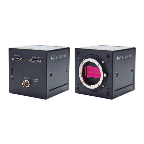
Page 13: Parts Identification
SW-4000T-MCL User Manual (2.0) Parts Identification Parts Identification ② Digital I/O-1 and Digital I/O-2 Video Output ① Lens Mount (M52-Mount or F-Mount) Connectors ③ POWER/TRIG LED ④ DC IN/TRIG Connector (12-Pin Round) ⑤ AUX Connector (10-pin) ⑥ ⑦ Mounting Holes ①... - Page 14 SW-4000T-MCL User Manual (2.0) Parts Identification Note: The cable length at which communication will be possible will be limited when using a cable that is not compatible with Camera Link, a small diameter type cable, or a high flex type cable.
-
Page 15: ③ Power/Trig Led
SW-4000T-MCL User Manual (2.0) Parts Identification ③ POWER/TRIG LED Indicates the power or trigger input status. Status Lit amber Camera initializing. Lit green Camera in operation During operation in trigger mode, trigger signals are being input. Blinking Note: The blinking interval is not related to the actual input interval of the green external trigger. - Page 16 SW-4000T-MCL User Manual (2.0) Parts Identification TTL Signal specification Output voltage: Low 0.0V, High 5.0V TTL out signal specification (Typ.) Input/Output current: +/-32mA TTL in signal specification (Typ.) Input voltage: Low 0.0 ~ 0.8V, High 2.0 ~ 5.5V Caution: About Opto In: Check the recommended external input circuit diagram (reference example) and connect correctly.
-
Page 17: ⑤ Aux Connector (10-Pin)
SW-4000T-MCL User Manual (2.0) Parts Identification ⑤ AUX Connector (10-pin) Connect the cable for DC IN / trigger IN here. Camera side: Equivalent to Hirose Electronic 3260-10S3(55) Cable side: Equivalent to Hirose Electronic 3240-10P-C(50) Pin No. Attribute Name Description TTL OUT2... -
Page 18: Preparation
Save the current setting configurations in user memory. Short ASCII Commands The most universal method for controlling a Camera Link camera such as SW-4000T-MCL is by the use of short ASCII commands sent via serial communications. All Camera Link frame grabber boards support the use of these short ASCII commands. -
Page 19: Step 1: Connect Devices
(Setting List). The SW-4000T-MCL fully supports applications written using GenICam-based SDKs. The advantage of this is that programs written using GenICam names can be applied with little or no modification to control cameras with other GenICam-compliant interfaces and even GenICam- compliant cameras from different vendors. -
Page 20: ① Lens
SW-4000T-MCL User Manual (2.0) Preparation ① Lens F-mount or M-52 mount lenses with lens mount protrusions of 13 mm or less can be attached. Caution: The maximum performance of the camera may not be realized depending on the lens. Notes: The following formula can be used to estimate the focal length. -
Page 21: ④ Frame Grabber Board
SW-4000T-MCL User Manual (2.0) Preparation Note: The maximum Camera Link cable length is 10 m. The maximum length of cable you can use will also vary depending on type and maker. If the CableEmphasis setting of TransportLayerControl is changed from Normal to Medium or Strong, it may be possible to lengthen the Camera Link cable. -
Page 22: Step 2: Verify Camera Operation
SW-4000T-MCL User Manual (2.0) Preparation Step 2: Verify Camera Operation When power is supplied to the camera while the necessary equipment is connected, the POWER/TRIG LED at the rear of the camera lights amber, and initialization of the camera starts. -
Page 23: Step 3: Verify The Connection Between The Camera And Pc
SW-4000T-MCL User Manual (2.0) Preparation Step 3: Verify the Connection Between the Camera and PC Use a short ASCII command to verify whether the camera is properly recognized in your setup. 1. Install terminal emulator software capable of serial communication to the PC connected to the camera via the frame grabber board. -
Page 24: Step 4: Configure Basic Settings For The Camera
SW-4000T-MCL User Manual (2.0) Preparation Step 4: Configure Basic Settings for the Camera Configure the Camera Output Formats Configure the pixel formats of the image output. 1. To check the current pixel format setting, enter the command BA?<CR><LF> from the terminal emulator software. -
Page 25: Configure Trigger, Exposure, And Line Rate Settings
SW-4000T-MCL User Manual (2.0) Preparation Configure Trigger, Exposure, and Line Rate Settings This section describes how to control the exposure time with or without external triggers. Note: For the details on the short ASCII commands required to configure the Trigger, Exposure and Line Rate settings, see "Acquisition... -
Page 26: Step 5: Adjust The Image Quality
SW-4000T-MCL User Manual (2.0) Preparation Step 5: Adjust the Image Quality Related Setting Items: AnalogControl Note: For the details on the short ASCII commands required to configure the image quality settings, see "Analog Control". To maximize the performance of the camera, configure its basic function in the following order. -
Page 27: Step 7: Save The Settings
SW-4000T-MCL User Manual (2.0) Preparation Step 7: Save the Settings Related Setting Items: UserSetControl The configured setting values will be deleted when the camera is turned off. By saving current setting values to user memory, you can load and recall them whenever necessary. You can save up to three sets of user settings in the camera. -
Page 28: Load The User Settings
SW-4000T-MCL User Manual (2.0) Preparation Load the User Settings 1. Stop image acquisition. User settings can only be loaded when image capture on the camera is stopped. 2. Specify the storage location (UserSet1 - UserSet3) using the UserSetLoad command and read the settings of the camera. -
Page 29: Main Functions
SW-4000T-MCL User Manual (2.0) Main Functions Main Functions This chapter describes the camera's main functions. Basic Function Matrix Valid Input / Output Combinations The following signals can be used as sources for each output destination (TriggerSelector, LineSelector, PulseGeneratorSelector). The combinations of source signals and output destinations are indicated in the following. -
Page 30: Gpio (Digital Input/Output Settings)
SW-4000T-MCL User Manual (2.0) Main Functions GPIO (Digital Input/Output Settings) Related Setting Items: DigitalIOControl The camera can input/output the following signals to and from external input/output connectors. TTL OUT 1 (Line 1) DC IN / TRIG IN Connector (12-pin) TTL OUT 4 (Line 12) -
Page 31: Camera Output Formats
SW-4000T-MCL User Manual (2.0) Main Functions For digital output, set the output source signal using LineSource. Set the source signal in the same way for NAND Logic (Nand0In1, Nand0In2, Nand1In1, Nand1In2). Note: For more information on the combinations of source signals and output destinations, Basic Function Matrix. -
Page 32: Clconfiguration Base - Pixelformat Rgb8
SW-4000T-MCL User Manual (2.0) Main Functions ClConfiguration Base - PixelFormat RGB8 Connector 1 Connector 1 Port / Bit 24-bit RGB Port A0 Port A1 Port A2 Port A3 Port A4 Port A5 Port A6 Port A7 Port B0 Port B1... -
Page 33: Clconfiguration Medium - Pixelformat Rgb8
SW-4000T-MCL User Manual (2.0) Main Functions ClConfiguration Medium - PixelFormat RGB8 Connector 1 Connector 2 Connector 1 Connector 2 Port / bit Custom Port / bit Custom Port A0 Port D0 Port A1 Port D1 Port A2 Port D2 Port A3... -
Page 34: Clconfiguration Medium - Pixelformat Rgb10
SW-4000T-MCL User Manual (2.0) Main Functions ClConfiguration Medium - PixelFormat RGB10 Connector 1 Connector 2 Connector 1 Connector 2 Port / bit 30-bit RGB Port / bit 30-bit RGB Port A0 Port D0 Port A1 Port D1 Port A2 Port D2... -
Page 35: Clconfiguration Full - Pixelformat Rgb8
SW-4000T-MCL User Manual (2.0) Main Functions ClConfiguration Full - PixelFormat RGB8 Connector 1 Connector 2 Connector 1 Connector 2 Port / bit 24-bit RGB Port / bit 24bit-RGB Port A0 Port D0 Port A1 Port D1 Port A2 Port D2... -
Page 36: Clconfiguration Eightybit - Pixelformat Rgb8
SW-4000T-MCL User Manual (2.0) Main Functions ClConfiguration EightyBit - PixelFormat RGB8 Connector 1 Connector 2 Connector 1 Connector 2 Port / bit 24-bit RGB Port / bit 24-bit RGB Port / bit 24-bit RGB Port A0 Port D0 Port G0... -
Page 37: Exposure Mode
SW-4000T-MCL User Manual (2.0) Main Functions Exposure Mode Related Setting Items: AcquisitionControl The following operation modes are available on the camera. Operation Mode Exposure Mode Trigger Mode Timed TriggerWidth Trigger Control Related Setting Items: AcquisitionControl The camera allows Line Start trigger controls to be performed via external trigger signals. -
Page 38: Image Output Timing
SW-4000T-MCL User Manual (2.0) Main Functions Shortest Trigger Pulse Width Trigger Mode ON Camera Link TTL In 3μs 50ns Image Output Timing Related Setting Items: AcquisitionControl This section shows the timing charts under the following conditions. ExposureMode = Off ExposureMode = Timed... -
Page 39: Exposuremode = Off
SW-4000T-MCL User Manual (2.0) Main Functions ExposureMode = Off Trigger Period (μs) Delay Time from Trigger to Exposure Active (ns) Exposure Active Non Active (μs) Period from Exposure Active Falling to LVAL Rising (μs) LVAL ACTIVE (μs) CL Clock PixelFormat... -
Page 40: Exposuremode = Timed
SW-4000T-MCL User Manual (2.0) Main Functions ExposureMode = Timed Trigger Period (μs) Delay Time from Trigger to Exposure Active (ns) Period from Exposure Active Falling to LVAL Rising (μs) LVAL ACTIVE (μs) PixelFormat CL Clock (MHz) Configuration 42.5 97.1 165 ~ 186 96.8... -
Page 41: Exposuremode = Triggerwidth
SW-4000T-MCL User Manual (2.0) Main Functions ExposureMode = TriggerWidth Trigger Period (μs) Delay Time from Trigger to Exposure Active (ns) Exposure Active Non Active (ns) Period from Exposure Active Falling to LVAL Rising (μs) LVAL ACTIVE (μs) CL Clock PixelFormat... -
Page 42: Pixel Sensitivity Correction
SW-4000T-MCL User Manual (2.0) Main Functions Pixel Sensitivity Correction Related Topic: JAI Custom Control Pixel Correction Correct variations between the sensor’s pixels. Calibration must be performed within the camera and correction data must be created beforehand. DSNU (PixelBlackCorrect) / PRNU (PixelGainCorrect) can be reduced using that correction data. -
Page 43: Dsnu Correction (Pixel Black Correct)
SW-4000T-MCL User Manual (2.0) Main Functions 2. Gain correction data is automatically generated by PerformPixelGainCalibration and saved in the user area specified in step 1. 3. You can check the execution result of gain correction by PixelGainDetectResult. Caution: This camera may take several minutes or more to complete PRNU correction. -
Page 44: Gain Control
SW-4000T-MCL User Manual (2.0) Main Functions Gain Control Related Setting Items: AnalogControl The following gain functions are available on the camera: Analog Base Gain and Digital Gain Analog Base Gain Analog base gain (ABG) is gain that is performed to the analog video signal output from the sensor. -
Page 45: Gamma Function
SW-4000T-MCL User Manual (2.0) Main Functions Gamma Function Related Setting Items: AnalogControl, The Gamma function corrects the output signals from the camera beforehand (reverse correction), taking into consideration the light-emitting properties of the monitor display. As the light-emitting properties of the monitor are not linear, the entire image may be darker or the gradation in the dark areas may be less noticeable when camera outputs are displayed without processing. -
Page 46: Lut (Lookup Table)
SW-4000T-MCL User Manual (2.0) Main Functions LUT (Lookup Table) Related Setting Items: LUTControl The LUT function is used to generate a non-linear mapping between signal values captured on the sensor and those that are output from the camera. On this camera, you can specify the output curve using 257 setting points (indexes). -
Page 47: Shading Correction
SW-4000T-MCL User Manual (2.0) Main Functions Shading Correction Related Setting Items: JAI Custom Control Shading The ShadingCorrection function corrects non-uniformity (i.e., shading) in the amount of light generated by the lens and lighting equipment. The following shading correction modes are available on the camera. -
Page 48: To Use The Shading Correction Function
SW-4000T-MCL User Manual (2.0) Main Functions To Use the Shading Correction Function The function is turned ON/OFF via serial communication. This function is not dependent on the operation mode but is effective when used during actual use. Note: You can save the setting, and have it applied whenever the power is subsequently turned on. -
Page 49: Variable Line Rate
SW-4000T-MCL User Manual (2.0) Main Functions Variable Line Rate Related Setting Items: AcquisitionControl You can set the line rate to 1L or more. This function can be used to match the scanning speed of the camera to the feeding speed of the object or to lengthen the accumulation time to increase sensitivity. -
Page 50: Number Of Pixels Per Line And Line Rate
SW-4000T-MCL User Manual (2.0) Main Functions Number of Pixels per Line and Line Rate You can increase the line rate by decreasing the number of pixels per line. Use Width (ASCII = WTC) to set the line width. Line rate can be increased to a maximum of 183.4 kHz for each configuration. -
Page 51: Electronic Shutter
SW-4000T-MCL User Manual (2.0) Main Functions Electronic Shutter Related Setting Items: AcquisitionControl When you use this function, you can set the exposure to a preconfigured accumulation time, regardless of the line rate. Variable range: 3 μs to 15.15 ms Variable unit: 0.01 μs (1clk) -
Page 52: Exposureactive Function
SW-4000T-MCL User Manual (2.0) Main Functions ExposureActive Function Related Setting Items: AcquisitionControl Perform external output for the timing at which video is accumulated to the sensor. The signal is output to the DC IN / TRIG IN connector (12-pin round) and the DIGITAL I/O-1 video output connector (Camera Link). -
Page 53: Color Space Conversion (Color Transformation Control)
SW-4000T-MCL User Manual (2.0) Main Functions Color Space Conversion (Color Transformation Control) Related Setting Items: ColorTransformationControl This camera allows you to convert the standard color space (RGB) that is used to produce colors into other color spaces, including XYZ and HSI. Five color spaces are available: RGB(sRGB), RGB(AdobeRGB), RGB(UserCustom), XYZ, and HSI. - Page 54 SW-4000T-MCL User Manual (2.0) Main Functions Configuration 3x3 table 1. Specify one of the nine items that are the components to the 3×3 conversion table in ColorMatrixValueSelector. 2. Specify a value from –2 to +2 in ColorMatrixValue. ColorTransformationControl for detailed information on the setting items.
-
Page 55: Counter And Timer Control Function
SW-4000T-MCL User Manual (2.0) Main Functions Counter and Timer Control Function Related Setting Items: CounterAndTimerControl Note: This camera supports only the counter function. The counter function counts up change points in the camera’s internal signals using the camera’s internal counter and reads that information from the host side. This function is useful for verifying error conditions via the count value using internal camera operations. -
Page 56: Counter Occurrence Diagram
SW-4000T-MCL User Manual (2.0) Main Functions Counter Occurrence Diagram Note: You can reset a specific counter's count value by executing CounterReset[Counter0, Counter1, Counter2, Counter3]. Internal Camera Blocks - 56 -... -
Page 57: To Use The Counter Function
SW-4000T-MCL User Manual (2.0) Main Functions To Use the Counter Function Configure the settings as follows. Eight counters are available. Specify a counter (Counter0 to Counter3), and configure the settings. Setting Value Item Description Selectable Range Counter 0 ~ 3 Counter 0 ~ 3 Select the counter. -
Page 58: Chromatic Aberration Correction
SW-4000T-MCL User Manual (2.0) Main Functions Chromatic Aberration Correction Related Setting Items: JAI Custom Control Pixel Correction This function corrects for the chromatic aberration of magnification caused by the lens (i.e., when the size of the image differs at the focal point for each color (RGB)). You can save correction data for three types of lenses. -
Page 59: Binning
SW-4000T-MCL User Manual (2.0) Main Functions Binning Related Setting Items: ImageFormatControl In this mode, a camera combines the charge collected in two adjacent pixels. This halves the effective resolution to 2048 pixels, but doubles the sensitivity (= Sum). On this camera, the line rate is not affected by Binning. -
Page 60: Connecting Rotary Encoders
SW-4000T-MCL User Manual (2.0) Main Functions Connecting Rotary Encoders Related Setting Items: EncoderControl This camera can generate trigger signals or detect the scanning direction of the subject in response to signals output from the rotary encoder. Adjustment Procedure 1. Input the two signals (phase A and phase B) from the rotary encoder. Select which I/O on... -
Page 61: Noise Reduction Filter Functions
SW-4000T-MCL User Manual (2.0) Main Functions Noise Reduction Filter Functions Related Setting Items: JAI Custom Control Pixel Correction The camera has noise reduction functions. The noise reduction methods vary depending on the channel. Three filters are available: MEDIAN Filter: Apply 1x3 MEDIAN filter Select the target to apply the filter from Red, Green, Blue, and set the Median Filter Mode. -
Page 62: Setting List
SW-4000T-MCL User Manual (2.0) Setting List Setting List This camera complies with GenICam. Each setting item name conforms to GenICam SFNC (Standard Features Naming Convention). (There are some JAI-specific setting items). Each setting item is an integer type (IInteger), a real type (IFloat), an element enumeration type (IEnumeration), a character string (IString), a logical type (IBoolean), and a category type (ICategory) or a command type (ICommand) for executing the function. -
Page 63: Devicecontrol
SW-4000T-MCL User Manual (2.0) Setting List DeviceControl Display/configure information related to the device. Setting DeviceControl Item Default Value Description Range "JAI Ltd., DeviceVendorName Display the manufacturer name. Japan" SW-4000T- DeviceModelName Display the model name. "See the DeviceManufacturerInfo Display the manufacturer information. -
Page 64: Imageformatcontrol
SW-4000T-MCL User Manual (2.0) Setting List ImageFormatControl Configure image format settings. Setting Default Image Format Control Item Description Range Value Set the image width. Max: 4096 (2048)* - OffsetX Width 4096 Min,Step: 16 (8)* Note: When BinningHorizontal = 2, the value in parentheses is applicable. -
Page 65: Acquisitioncontrol
SW-4000T-MCL User Manual (2.0) Setting List AcquisitionControl Configure image capture settings. Acquisition Control Item Setting Range Default Value Description AcquisitionLineRate (Hz) 66 to 67702 Set the AcquisitionLineRate(Hz). Related Topic: (steps of 0.1) Variable Line Rate TriggerMode 0:Off 0:Off Select the trigger mode. - Page 66 SW-4000T-MCL User Manual (2.0) Setting List Acquisition Control Item Setting Range Default Value Description Specify the sensor for which to set the ExposureTime. Select Common if ExposureTimeMode is set to Common. Select 0: Common Red/Green/Blue if ExposureTimeMode is set to Individual.
-
Page 67: Analogcontrol
SW-4000T-MCL User Manual (2.0) Setting List AnalogControl Configure the analog control settings. Default Analog Control Item Setting Range Description Value IndividualGainMode 0:Off In IndividualGainMode, RGB can be configured individually for the entire 0:Off Related Topic: gain adjustment range of the sensor. - Page 68 SW-4000T-MCL User Manual (2.0) Setting List Default Analog Control Item Setting Range Description Value When BalanceWhiteAuto is set to Once, specify the width of the reference area. Min: 16(8)* AWBAreaWidth Max:4096 (2048)* Step: 16(8)* *When BinningHorizontal = 2, the value in parenthesis is applicable.
-
Page 69: Lutcontrol
SW-4000T-MCL User Manual (2.0) Setting List Default Analog Control Item Setting Range Description Value Display the status when GainAuto is set to Once. 1: Succeeded. AGCOnceStatus 2: Error1- Timeout-error occurred. 3: Abort1-Control Limit 4: IDLE (Default) Gamma Set the Gamma value. -
Page 70: Colortransformationcontrol
SW-4000T-MCL User Manual (2.0) Setting List ColorTransformationControl Configure color transformation settings. Related Topic: Color Space Conversion (Color Transformation Control) Color Transformation Control Setting Default Description Item Range Value 0:RGB ColorTransformationMode 1: HSI 0:RGB Set the output image format. 2: XYZ... -
Page 71: Digitaliocontrol
SW-4000T-MCL User Manual (2.0) Setting List DigitalIOControl Configure settings for digital input/output. Related Topic: GPIO (Digital Input/Output Settings) Default Digital IO Control Item Setting Range Description Value (IO Connecter) Line5: Opt In1 Line4: TTL In1 Line1: TTL Out1 Line12: TTL Out4... - Page 72 SW-4000T-MCL User Manual (2.0) Setting List Default Digital IO Control Item Setting Range Description Value 0: Low 1: High 7: ExposureActive 9: LVAL 10: PulseGenerator0 11: PulseGenerator1 12: PulseGenerator2 13: PulseGenerator3 14: UserOutput0 15: UserOutput1 LineSource 16: UserOutput2 0: Low Select the line source signal for the item selected in LineSelector.
-
Page 73: Counterandtimercontrol
SW-4000T-MCL User Manual (2.0) Setting List CounterAndTimerControl Configure counter settings. Note: This camera only supports the counter functions. Related Topic: Counter and Timer Control Function CounterAndTimer Setting Default Description Control Item Range Value 0 ~ 3: CounterSelector 0: Counter0 Select the counter. -
Page 74: Usersetcontrol
SW-4000T-MCL User Manual (2.0) Setting List UserSetControl Configure user settings. Related Topic: Step 7: Save the Settings User Set Control Setting Default Description Item Range Value Select the user settings. 0: Default - Invalid when executing UserSetSave UserSetSelector 0: Default... -
Page 75: Pulsegenerator
SW-4000T-MCL User Manual (2.0) Setting List PulseGenerator Configure pulse generator settings. Pulse Generator Item Setting Range Default Value Description Set the division value for the prescaler (12 bit) ClockPreScaler 1 ~ 4096 using PixelClock as the base clock. Set the clock used for the pulse generator. This... - Page 76 SW-4000T-MCL User Manual (2.0) Setting List Pulse Generator Item Setting Range Default Value Description Set the start point of the Low interval in milliseconds. When the counter reaches this (1 / value, the output will be 0. The setting range varies...
-
Page 77: Jai Custom Control Shading
SW-4000T-MCL User Manual (2.0) Setting List Pulse Generator Item Setting Range Default Value Description Controls if the pulse generator clear signal is 0:False PulseGeneratorClearInverter 0:False inverted. False means "Active High" and True for 1:True "Active Low". PulseGeneratorClear 0:Async Mode Select the sync mode for the count clear input... -
Page 78: Jai Custom Control Pixel Correction
SW-4000T-MCL User Manual (2.0) Setting List JAI Custom Control Pixel Correction Configure settings related to the correction function for nonuniformity in black levels and gain between pixels. Setting Default Correction Control Item Description Range Value PixelBlackCorrectionMode 0: Off (DSNU) Select the user area to which to save the black level 1: Default correction value. -
Page 79: Jai Custom Control Image Setup
SW-4000T-MCL User Manual (2.0) Setting List Setting Default Correction Control Item Description Range Value ChromaticAberration 0: Off CorrectionMode 1:Lens1 Correct the color aberration that occurs at the left and right edges 0: Off due to lens characteristics. 2:Lens2 Related Topic:... -
Page 80: Jai Custom Control Video Process
SW-4000T-MCL User Manual (2.0) Setting List JAI Custom Control Video Process Configure the chromatic Aberration Correction settings. Video Process Control 項 目 設 定 範 囲 初 期 値 説 明 ChromaticAberrationCorrectionMode CACM=[Param.]<CR><LF> 0: Off CACM?<CR><LF> 1:Lens1 0: Off Related Topic:... - Page 81 SW-4000T-MCL User Manual (2.0) Setting List Default Encoder Control Item Setting Range Description Value Apply a low-pass filter to prevent noise on the signal from the rotary encoder and stabilize the signal for the specified number of cycles. EncoderFilter (cycle)
-
Page 82: Short Ascii Command List
SW-4000T-MCL User Manual (2.0) Short ASCII Command List Short ASCII Command List All configuration of the camera is done via the RS-232C port. The camera can be set up from a PC running terminal emulator software. Below is the description of the ASCII based short command protocol. - Page 83 SW-4000T-MCL User Manual (2.0) Short ASCII Command List Switching baud rate between PC and camera Camera always starts up with 9600bps. This can be switched to higher baud rates after a communication has been established. When switching to other baud rate the procedure is as follows.
-
Page 84: Device Control
SW-4000T-MCL User Manual (2.0) Short ASCII Command List Device Control Display/configure information related to the device. Note: Descriptions of each command can also be found in "DeviceControl" (Setting List). Short Default Device Control Name Access Values Example / Description ASCII Value DVN?<CR><LF>... -
Page 85: Technology Specific Bootstrap Register
SW-4000T-MCL User Manual (2.0) Short ASCII Command List Technology Specific Bootstrap Register Short Name Access Values MIN MAX Default Description ASCII Indicate Support/Non- support status for SBDRT?<CR><LF> each baud rate Display the supported transmission baud rate SupportedBaud bit0: 9600bps SBDRT 0x01 0xFF... -
Page 86: Image Format Control
SW-4000T-MCL User Manual (2.0) Short ASCII Command List Image Format Control Configure image format settings. Note: Descriptions of each command can also be found in "ImageFormatControl" (Setting List). Image Format Short Default Access Values Example / Description Control Name ASCII Value WTC=[Param.]<CR><LF>... -
Page 87: Acquisition Control
SW-4000T-MCL User Manual (2.0) Short ASCII Command List Acquisition Control Configure image capture settings. Note: Descriptions of each command can also be found in "AcquisitionControl" (Setting List). Acquisition Control Short Default Access Values Example / Description Name ASCII Value LR=[Param.]<CR><LF> LR?<CR><LF> Use this command to set the line rate of the... - Page 88 SW-4000T-MCL User Manual (2.0) Short ASCII Command List Acquisition Control Short Default Access Values Example / Description Name ASCII Value ETM=[Param.]<CR><LF> ETM?<CR><LF> 0:Common Select the exposure time mode. ExposureTimeMode 1:Individual Common: Set the common value for R, G and B channels. Individual: Set the values for the R, G, and B channels individually PE=[Param.]<CR><LF>...
-
Page 89: Analog Control
SW-4000T-MCL User Manual (2.0) Short ASCII Command List Acquisition Control Short Default Access Values Example / Description Name ASCII Value EI=[Param.]<CR><LF> EI?<CR><LF> 0:Off RBExposureInterlocked Adjust exposure time of the R and B channels 1:On automatically in conjunction with exposure time of the G channel. - Page 90 SW-4000T-MCL User Manual (2.0) Short ASCII Command List Analog Control Short Default Access Values Example / Description Name ASCII Value GAB=[Param.]<CR><LF> IndividualGainMode = Off: GAB?<CR><LF> 40 ~ 400 GainInt[DigitalBlue] IndividualGainMode = On: Set Gain[DigitalBlue]. The setting range varies 100 ~ 1600 depending on the IndividualGainMode setting.
- Page 91 SW-4000T-MCL User Manual (2.0) Short ASCII Command List Analog Control Short Default Access Values Example / Description Name ASCII Value 1=Succeeded. 2=Error1 - G image was too bright. AWHS?<CR><LF> AWBExposureOnce 3=Error2 - G image was too AHRS Displays the status at the time of execution Status dark.
- Page 92 SW-4000T-MCL User Manual (2.0) Short ASCII Command List Analog Control Short Default Access Values Example / Description Name ASCII Value GMA=[Param.]<CR><LF> GMA?<CR><LF> Controls the gamma correction of pixel Gamma GMA 40 ~ 100 intensity. This is typically used to compensate for non-linearity of the display system (such as CRT).
-
Page 93: Lut Control
SW-4000T-MCL User Manual (2.0) Short ASCII Command List LUT Control Configure LUT settings. Note: Descriptions of each command can also be found in "LUTControl" (Setting List). Short Default Lut Control Name Access Values Example / Description ASCII Value LUTIR=[Param.]<CR><LF> LUTIR?<CR><LF> LUTIndex [Red]... -
Page 94: Color Transformation Control
SW-4000T-MCL User Manual (2.0) Short ASCII Command List Color Transformation Control Configure color transformation settings. Note: Descriptions of each command can also be found in "ColorTransformationControl" (Setting List). Color Transformation Short Default Access Values Example / Description Control Name ASCII Value CTM=[Param.]<CR><LF>... - Page 95 SW-4000T-MCL User Manual (2.0) Short ASCII Command List Color Transformation Short Default Access Values Example / Description Control Name ASCII Value CMVGR=[Param.]<CR><LF> CMVGR?<CR><LF> Specify the ColorMatrix value. ColorMatrixValueInt [G-R] CMVGR -20000 ~ 20000 ColorTransformationMode = RGB ColorTransformationRGBMode=UserCustom Individually adjust 9 elements of the 3x3 color matrix (G-R) CMVGG=[Param.]<CR><LF>...
-
Page 96: Digital Io Control
SW-4000T-MCL User Manual (2.0) Short ASCII Command List Color Transformation Short Default Access Values Example / Description Control Name ASCII Value CMVBB=[Param.]<CR><LF> CMVBB?<CR><LF> Specify the ColorMatrix value. ColorMatrixValueInt [B-B] CMVBB -20000 ~ 20000 ColorTransformationMode = RGB ColorTransformationRGBMode=UserCustom Individually adjust 9 elements of the 3x3 color... - Page 97 SW-4000T-MCL User Manual (2.0) Short ASCII Command List Digital IO Control Short Default Access Values Example / Description Name ASCII Value ND0INV2=[Param.]<CR><LF> ND0INV2?<CR><LF> 0: False LineInverter ND0INV2 [NANDGate0In2] 1: True Invert the polarity of the signal (NANDGate0In1). ND1INV1=[Param.]<CR><LF> ND1INV1?<CR><LF> 0: False LineInverter...
- Page 98 SW-4000T-MCL User Manual (2.0) Short ASCII Command List Digital IO Control Short Default Access Values Example / Description Name ASCII Value ND0IN1=[Param.]<CR><LF> ND0IN1?<CR><LF> LineSource ND0IN1 Same as LS0 [NANDGate0In1] Select signal to be passed to the Line NANDGate0In1. ND0IN2 =[Param.]<CR><LF> ND0IN2?<CR><LF> LineSource...
-
Page 99: Counter And Timer Control
SW-4000T-MCL User Manual (2.0) Short ASCII Command List Counter and Timer Control Configure counter settings. Notes: This camera only supports the counter functions. Descriptions of each command can also be found in "CounterAndTimerControl" (Setting List). Counter and Timer Short Default Access Values... -
Page 100: User Set Control
SW-4000T-MCL User Manual (2.0) Short ASCII Command List Counter and Timer Short Default Access Values Example / Description Control Name ASCII Value CV2?<CR><LF> CounterValue [Counter2] 0 ~ 4294967295 Display the Counter2's value. CV3?<CR><LF> CounterValue [Counter3] 0 ~ 4294967295 Display the Counter3's value. -
Page 101: Transport Layer Control
SW-4000T-MCL User Manual (2.0) Short ASCII Command List Transport Layer Control Display information on transport layer control. Note: Descriptions of each command can also be found in "TransportLayerControl" (Setting List). Transport Layer Control Short Default Access Values Example / Description Name ASCII... -
Page 102: Pulse Generator
SW-4000T-MCL User Manual (2.0) Short ASCII Command List Pulse Generator Configure pulse generator settings. Note: Descriptions of each command can also be found in "PulseGenerator" (Setting List). Short Default Pulse Generator Name Access Values Example / Description ASCII Value PGDEV=[Param.]<CR><LF> PGDEV?<CR><LF> ClockPreScaler... - Page 103 SW-4000T-MCL User Manual (2.0) Short ASCII Command List Short Default Pulse Generator Name Access Values Example / Description ASCII Value PGST1=[Param.]<CR><LF> PGST1?<CR><LF> Set the start point of the High PulseGeneratorStartPoint PGST1 0 ~ 1048575 interval as a clock count for [PulseGenerator1] PulseGenerator1. When the counter reaches this value, the output will be 1.
- Page 104 SW-4000T-MCL User Manual (2.0) Short ASCII Command List Short Default Pulse Generator Name Access Values Example / Description ASCII Value PGEN3=[Param.]<CR><LF> PGEN3?<CR><LF> Set the start point of the Low PulseGeneratorEndPoint PGEN3 0 ~ 1048575 interval as a clock count for [PulseGenerator3] PulseGenerator3. When the counter reaches this value, the output will be 0.
- Page 105 SW-4000T-MCL User Manual (2.0) Short ASCII Command List Short Default Pulse Generator Name Access Values Example / Description ASCII Value PGCM1 =[Param.]<CR><LF> 0: Off PGCM1 ?<CR><LF> 1: Level High PulseGeneratorClearActivation PGCM1 2: Level Low Set the clear signal condition for [PulseGenerator1] 4: Rising Edge...
- Page 106 SW-4000T-MCL User Manual (2.0) Short ASCII Command List Short Default Pulse Generator Name Access Values Example / Description ASCII Value PGIN2=[Param.]<CR><LF> Same as PGIN0 PGIN2?<CR><LF> PulseGeneratorClearSource PGIN2 Note: 12: Select the count clear input [PulseGenerator2] PulseGenerator2 cannot signal source for be selected.
-
Page 107: Jai Custom Control Shading
SW-4000T-MCL User Manual (2.0) Short ASCII Command List Short Default Pulse Generator Name Access Values Example / Description ASCII Value PGSM1=[Param.]<CR><LF> PGSM1?<CR><LF> 0:Async Mode PulseGeneratorClearSyncMode PGSM1 [PulseGenerator1] 1:Sync Mode Selects the sync mode of the input to clear PulseGenerator1. PGSM2=[Param.]<CR><LF> PGSM2?<CR><LF> 0:Async Mode... - Page 108 SW-4000T-MCL User Manual (2.0) Short ASCII Command List Short Default Shading Control Name Access Values Example / Description ASCII Value 0: Condition Error 1: Too Dark SDRS?<CR><LF> ShadingDetectResult SDRS 2: Too Bright Display the shading correction results. 3: Correction Limit 4: Complete SDDS=[Param.]<CR><LF>...
-
Page 109: Jai Custom Control Pixel Correction
SW-4000T-MCL User Manual (2.0) Short ASCII Command List JAI Custom Control Pixel Correction Configure settings related to the correction function for nonuniformity in black levels and gain between pixels. Note: Descriptions of each command can also be found in "JAI Custom Control Pixel Correction"... - Page 110 SW-4000T-MCL User Manual (2.0) Short ASCII Command List Short Default Correction Control Name Access Values Example / Description ASCII Value 1: Succeeded PGS?<CR><LF> 2: Image too bright PixelGainDetectResult (PRNU) Display the results of 3: Image too dark PerformPixelGainCalibration execution. 4: Timeout error FFR=[Param.]<CR><LF>...
- Page 111 SW-4000T-MCL User Manual (2.0) Short ASCII Command List Short Default Correction Control Name Access Values Example / Description ASCII Value FFRRR=[Param.]<CR><LF> FFRRR?<CR><LF> FIRFilterRightRatioInt [Red] FFRRR -200 ~ 200 Set the coefficient of the right pixel when FIR Filter for Red is applied.
-
Page 112: Jai Custom Control Image Setup
SW-4000T-MCL User Manual (2.0) Short ASCII Command List JAI Custom Control Image Setup Configure the Horizontal Image Mirroring setting. Note: Descriptions of each command can also be found in "JAI Custom Control Image Setup" (Setting List). Short Default Image Setup Name Access... - Page 113 SW-4000T-MCL User Manual (2.0) Short ASCII Command List Short Default Video Process Control Name Access Values Example / Description ASCII Value CACB2=[Param.]<CR><LF> -40 ~ 40 CACB2?<CR><LF> ChromaticAberrationCorrectionLens CACB2 [Lens2, B channel] Unit: 0.1 pixel Set the amount of correction for the Lens2/B channel.
-
Page 114: Encoder Control
SW-4000T-MCL User Manual (2.0) Short ASCII Command List Encoder Control Configure Encoder settings. Note: Descriptions of each command can also be found in "EncoderControl" (Setting List). Short Default Encoder Control Name Access Values Example / Description ASCII Value ENCSA=[Param.]<CR><LF> 0: Line5 Opt In1 ENCSA?<CR><LF>... -
Page 115: Miscellaneous
SW-4000T-MCL User Manual (2.0) Miscellaneous Miscellaneous Troubleshooting Check the following before requesting help. If the problem persists, contact your local JAI distributor. Power Supply and Connections Issue: The POWER/TRIG LED remains lit amber and does not turn green, even after power is supplied to the camera. -
Page 116: Specifications
SW-4000T-MCL User Manual (2.0) Miscellaneous Specifications Item 4K line scan CMOS image sensor × 3 Image Sensor Effective Pixels: 4096 pixels × 3 (R, G, B) Pixel Size: ModeA: 7.5 μm x 7.5 μm, ModeB: 7.5 μm x 10.5 μm Camera Link Clock 42.5 / 63.75 / 85 MHz... - Page 117 SW-4000T-MCL User Manual (2.0) Miscellaneous Item 1. Pixel sensitivity correction: Pixel correction (DSNU, PRNU) 2.Shading correction: ColorShading, FlatShading Image Processing 3. LUT: OFF: γ = 1.0, ON: 257 points can be set 4. Gamma: 0.45, 0.5, 0.55, 0.6, 0.65, 0.75, 0.8, 0.9, 1.0 (9 steps available) 5.
-
Page 118: Package Contents
SW-4000T-MCL User Manual (2.0) Miscellaneous Item Model: HDR-EC26FYTG2-SLt × 2 Mini Camera Link Function: video output / communication / external trigger / ExposureActive *Positive polarity for ExposureActive (polarity switching not possible) Model: HR10A-10R-12PB(71) (or equivalent) 12-pin Function: power supply input / communication / external trigger / ExposureActive... -
Page 119: Spectral Response
SW-4000T-MCL User Manual (2.0) Miscellaneous Spectral Response - 119 -... -
Page 120: Dimensions (F-Mount)
SW-4000T-MCL User Manual (2.0) Miscellaneous Dimensions (F-Mount) Notes: Dimensional Tolerance: ± 0.3mm Unit: mm - 120 -... -
Page 121: Dimensions (M52-Mount)
SW-4000T-MCL User Manual (2.0) Miscellaneous Dimensions (M52-Mount) Notes: Dimensional Tolerance: ± 0.3mm Unit: mm - 121 -... -
Page 122: Comparison Of The Decibel Display And Multiplier Display
SW-4000T-MCL User Manual (2.0) Miscellaneous Comparison of the Decibel Display and Multiplier Display Decibels [dB] Multipliers [X] Remarks 0.501 0.562 0.631 0.708 0.794 0.891 1.122 1.259 1.413 1.585 1.778 1.995 2.239 2.512 2.818 3.162 3.548 3.981 4.467 5.012 5.623 6.31 7.079... -
Page 123: User's Record
SW-4000T-MCL User Manual (2.0) Miscellaneous Decibels [dB] Multipliers [X] Remarks 50.119 56.234 63.096 User's Record Model name: SW-4000T-MCL Revision: …………… Serial No: …………… Firmware version: …………… For camera revision history, please contact your local JAI distributor. - 123 -... -
Page 124: Revision History
SW-4000T-MCL User Manual (2.0) Revision History Revision History Device Revision Date Changes Version Redesigned the user manual and updated/corrected topics. Added the Command List (Short ASCII Command List). 2023/09/13 DV0119 ~ Added Encoder Max Trigger Period (EncoderControl). Added a caution and notes to...
Need help?
Do you have a question about the SW-4000T-MCL and is the answer not in the manual?
Questions and answers