Table of Contents
Advertisement
Quick Links
User Manual
SW-8000M-PMCL
Monochrome Line Scan Camera
Document Version: 1.�
SW-8000M-PMCL_Ver.1.�_���.2020
Thank you for purchasing this product.
Be sure to read this manual before use.
This manual includes important safety precautions and
instructions on how to operate the unit. Be sure to read this
manual to ensure proper operation.
© 2017 JAI
Advertisement
Table of Contents

Related Manuals for IAI SW-8000M-PMCL


Summary of Contents for IAI SW-8000M-PMCL
- Page 1 User Manual SW-8000M-PMCL Monochrome Line Scan Camera Document Version: 1.� SW-8000M-PMCL_Ver.1.�_���.2020 Thank you for purchasing this product. Be sure to read this manual before use. This manual includes important safety precautions and instructions on how to operate the unit. Be sure to read this manual to ensure proper operation.
-
Page 2: Table Of Contents
SW-8000M-PMCL Contents Notice/Warranty/Certifications EEN (Exposure Enable) Function Usage Precautions Test Pattern Function Features Binning Parts Identifications RS-232C Command Control Field Upgrade Function Preparation Noise reduction digital filter function Preparation Flow Step 1:Installing the Software Setting List Step 2:Connecting Devices Setting List... -
Page 3: Notice/Warranty/Certifications
CE compliance As defined by the Directive 2004/108/EC of the European Parliament and of the Council, EMC (Electromagnetic compatibility), JAI Ltd., Japan declares that SW-8000M-PMCL complies with the following provisions applying to its standards. EN 61000-6-3 (Generic emission standard part 1) - Page 4 SW-8000M-PMCL Supplement The following statement is related to the regulation on “ Measures for the Administration of the control of Pollution by Electronic Information Products “ , known as “ China RoHS “. The table shows contained Hazardous Substances in this camera.
-
Page 5: Usage Precautions
SW-8000M-PMCL Usage Precautions Notes on cable configurations The presence of lighting equipment and television receivers nearby may result in video and audio noise. In such cases, change the cable configurations or placement. Notes on Camera Link cable connections Secure the locking screws on the connector manually, and do not use a driver. -
Page 6: Features
SW-8000M-PMCL Features The SW-8000M-PMCL is a line scan camera equipped with a 8192-pixel CMOS linear sensor. The camera has a Camera Link clock of 84.82 MHz and is capable of high-speed scanning at up to 99.9 kHz (Line Rate). 8-bit and 10-bit video output is possible via Camera Link. -
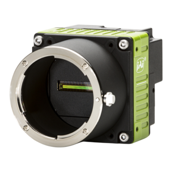
Page 7: Parts Identifications
SW-8000M-PMCL Parts Identification 1 Lens mount (M42 mount or F mount) Mount an M42-mount lens or F-mount lens here. Before mounting a lens, be sure to refer to “Step 2: Connecting Devices” (page 12) and confirm the precautions for attaching a lens and the supported lens types. - Page 8 SW-8000M-PMCL 3 DC IN / trigger IN connector ( 12-pin round) Connect the cable for a power supply (sold separately) or for DC IN / trigger IN here. HR-10A-10R-12PB (71) (Hirose Electric or equivalent) Input/ Pin No. Signal Description output...
- Page 9 SW-8000M-PMCL Connector 2 (used during Medium, Full, 8/10 bit output) Input/ Pin No. Signal Description output 1, 26 Power Power 2 (-), 15 (+) TxOUT0 Data output 3 (-), 16 (+) TxOUT1 Data output 4 (-), 17 (+) TxOUT2 Data output...
-
Page 10: Preparation
SW-8000M-PMCL Preparation Preparation Flow Step 1 Installing the Software (first time only) Install the software for configuring and controlling the camera (JAI SDI) on the computer. Step 2 Connecting Devices Connect the lens, Camera Link cable, AC adapter, computer, and other devices. - Page 11 Clear the [JAI GigE Vision Filter Driver] checkbox, and save. Verify the settings for using Camera Link. The SW-8000M-PMCL supports GenIcam and Gen-CP. Check the following settings when controlling the camera via JAI SDK. Checking the frame grabber board’s settings Settings must be configured on the frame grabber board to enable Gen-CP support.
-
Page 12: Step 2:Connecting Devices
SW-8000M-PMCL v Check that the [JAI_GenCP_Camera_Link] and [Camera Link Transport Layer] settings are configured as follows. Step 2: Connecting Devices Connect the lens, Camera Link cable, AC adapter, and other necessary devices. Attach the lens in a clean environment to prevent dust from adhering to the unit. - Page 13 SW-8000M-PMCL 1 Lens Attach an M42-mount lens or F-mount lens. Caution The maximum performance of the camera may not be realized depending on the lens. Note The following formula can be used to estimate the focal length. focal length = WD/(1 + W/w)
-
Page 14: Step 3:Verifying Camera Operation
SW-8000M-PMCL Step 3: Verifying the Camera Connection Status When the necessary devices are connected and power is supplied to the camera, the POWER/TRIG LED at the rear of the camera lights amber, and initialization of the camera starts. When initialization is complete, the POWER/TRIG LED lights green. -
Page 15: Control Via External Triggers
SW-8000M-PMCL Control via External Triggers When Controlling the Exposure Time Using Specified Exposure Times Configure the settings as follows. Item Setting value / selectable range Trigger Selector (trigger operation) Line Start Trigger Mode Trigger Source (trigger signal source) Trigger Activation (trigger polarity) -
Page 16: Control Without External Triggers
SW-8000M-PMCL Control Without External Triggers When Controlling the Exposure Time Using Specified Exposure Times Configure the settings as follows. Item Setting value / selectable range Trigger Selector (trigger operation) Line Start Trigger Mode Exposure Mode Timed (control via exposure time) -
Page 17: Step 6:Configuring Various Other Settings
SW-8000M-PMCL Procedure u Close the lens aperture. v Set [Pixel Black Correct] to [User]. w Execute [Pixel Black Direct], and perform calibration. Perform PRNU calibration. The camera is equipped with a PRNU correction function. The function allows you to reduce PRNU generated ❖... - Page 18 SW-8000M-PMCL ■ To save user settings Stop image capture. Expand [User Set Control] and select the save destination ([User Set1] to [User Set3]) in [User Set Selector]. Note The factory default setting values are stored in [Default] and cannot be overwritten.
-
Page 19: Basic Function Matrix
SW-8000M-PMCL Basic Function Matrix Valid Input/Output Combinations The following signals can be used as sources for each output destination (Trigger Selector). The combinations of source signals and output destinations are indicated in the following. Selector Output destination (Cross point Trigger Selector... -
Page 20: Main Functions
Select in [Line Selector] > [Line Source]. Camera Output Formats The SW-8000M-PMCL supports a variety of output formats. The supported tap geometries are as follows. The tap geometry settings on the camera side and the frame grabber board side must match. For details on frame grabber board settings, refer to the instruction manual of the board. -
Page 21: Image Output Timing
SW-8000M-PMCL For details on operation mode and function combinations, see “Basic Function Matrix” (page 19). Image Output Timing ■ Trigger Control The camera allows Line Start trigger controls to be performed via external trigger signals. The Line Start trigger allows exposure control via the trigger signal inputs. - Page 22 SW-8000M-PMCL ■ When [ExposureMode] is [Off] • Line Start Trigger : Off LVAL DVAL • Common to [Binning Off] and [Vertical Binning On] Period from Data Data Actual EEN Falling CL Pixel Line Period EEN invalid invalid time valid time...
- Page 23 SW-8000M-PMCL ■ When [ExposureMode] is [Off] Next trigger input Next trigger start prohibited period allowed period • Line Start Trigger : On Trigger LVAL DVAL • Common to [Binning Off] and [Vertical Binning On] Period From Delay time Data Data...
- Page 24 SW-8000M-PMCL ■ When [ExposureMode] is [Timed] • Line Start Trigger : Off Shutter select mode Set Value + Offset(B) LVAL DVAL • Common to [Binning Off] and [Vertical Binning On] Period From Exposure EEN Falling Data Data CL Pixel Line Period...
- Page 25 SW-8000M-PMCL ■ When [ExposureMode] is [Timed] • Line Start Trigger : On Shutter select mode Next trigger start prohibited period Next trigger input allowed period Trigger B Set Value + Offset(C) LVAL DVAL • Common to [Binning Off] and [Vertical Binning On]...
- Page 26 SW-8000M-PMCL ■ When [ExposureMode] is [TriggerWidth] • Line Start Trigger : On PWC mode Trigger LVAL DVAL • Common to [Binning Off] and [Vertical Binning On] Delay Time Delay time Period from from Trigger From Trigger EEN Falling Data Data...
-
Page 27: Pixel Sensitivity Correction
SW-8000M-PMCL Pixel Sensitivity Correction Correct variations between the sensorʼs pixels. Calibration must be performed within the camera and correction data must be created beforehand. DSNU (PixelBlackCorrect) / PRNU (PixelGainCorrect) can be reduced using that correction data. We recommend performing calibration and creating correction data whenever the line rate setting or Analog base gain setting or vertical binning setting are changed significantly. -
Page 28: Gain Control
SW-8000M-PMCL Gain Control The following gain functions are available on the camera. • Analog base gain • Digital gain ■ Analog base gain Analog base gain (ABG) is gain that is performed to the analog video signal output from the sensor. -
Page 29: Shadingcorrection
SW-8000M-PMCL Shading Correction The shading correction is a function that corrects non-uniformity (i.e., shading) in the amount of light generated by the lens and lighting equipment. The following shading correction modes are available on the camera. ■ Flat shading correction The range of brightness that can be corrected is within ±30% of the region with the highest signal level... -
Page 30: Electronic Shutter
SW-8000M-PMCL ■ Auto line rate configuration function You can automatically configure the optimal line rate when you want to prioritize sensitivity. • Supported operation modes: When Trigger Mode OFF, Exposure Mode OFF You can also save the setting and have it applied whenever the power is subsequently turned on. For details on saving the setting, see “Step 7: Saving the Settings”... -
Page 31: Test Pattern Function
SW-8000M-PMCL Test Pattern Function You can display the following types of test patterns. Video output is not possible while a test pattern is being executed. This function is not dependent on gain and offset values that have already been configured, and output is performed in the following states. -
Page 32: Binning
SW-8000M-PMCL Binning The binning function allows you to combine the signal values of clusters of adjacent pixels to create improved virtual pixels. Using the function results in images with lower pixel resolution and higher sensitivity. This camera performs horizontal binning via digital addition or averaging processing. -
Page 33: Setting List
SW-8000M-PMCL Settings List Control Tool : Settings that can only be configured when image capture on the camera is stopped. Item Setting range Default value Description a) Device Control GenCP Version — — Display/configure information related to the device. Device Vendor Name —... - Page 34 SW-8000M-PMCL Item Setting range Default value Description Black Level Selector Black Level –133 to 255 Set the black level value. Gain Selector Digital All Digital All 1 to 64 Gain Set the gain value by multipliers. Analog Base Gain 0dB, Set the analog base gain.
-
Page 35: Miscellaneous
SW-8000M-PMCL Miscellaneous Troubleshooting Check the following before requesting help. If the problem persists, contact your local JAI distributor. ■ Power supply and connections Problem Cause and solution The POWER/TRIG LED remains lit amber and • A drop in voltage may have occurred due to the length of does not turn green, even after power is the power cable. -
Page 36: Specifications
SW-8000M-PMCL Specifications Custom Image sensor Model Effective pixels 8192(H) Pixel size 3.75 µm × 5.78 µm Camera Link clock 31.70/42.41/63.39/84.82 MHz Line rate 66 Hz - 99.9 kHz Video S/N ratio 60 dB or more (when Gain = 0 dB) (10-bit) PRNU Post-correction: Within ±5% (during 100% output) - Page 37 SW-8000M-PMCL Power supply voltage DC input range: +12 V to 24 V ±10% 5.22W typical (current consumption at DC +12 V supply) Lens mount M42 mount, F mount Flange back M42 mount: 16 mm (in air), tolerance: 0 mm to –0.05 mm F mount: 46.5 mm, tolerance: 0 mm to –0.05 mm...
-
Page 38: Spectral Response
SW-8000M-PMCL Spectral Response SW-8000 Sensitivity 1.00 0.90 0.80 0.70 0.60 0.50 SW-8000 0.40 0.30 0.20 0.10 0.00 1000 wavelength (nm) — 38 —... -
Page 39: Dimensions
SW-8000M-PMCL Dimensions M42 Mount POWER/TRIG DC IN / TRIG DIGITAL I/O -2 DIGITAL I/O -1 Dimensional tolerance: ±0.3 mm Unit: mm — 39 —... - Page 40 SW-8000M-PMCL F Mount POWER/TRIG DC IN / TRIG DIGITAL I/O -2 DIGITAL I/O -1 Dimensional tolerance: ±0.3 mm Unit: mm — 40 —...
- Page 41 SW-8000M-PMCL Trademarks • Microsoft and Windows are trademarks or registered trademarks of Microsoft Corporation in the United States and other countries. • Intel and Intel Core are trademarks of Intel Corporation in the United States and other countries. Other system and product names described in this document are trademarks or registered trademarks of their respective owners.
-
Page 42: Index
SW-8000M-PMCL Index 12-pin round Lens Lens mount Binning Function Lookup Table Black level Camera locking screw holes Output format Connecting Devices Parts Identification DC IN POWER/TRIG LED DC IN/TRIG connector Digital Input/Output Settings Dimensions Saving the Settings Settings List E... - Page 43 Revision history Revision Date Changes First draft Jan. 2020 Camera locking screw holes size was fixed. Oct. 2020 China RoHS Dec. 2020...
Need help?
Do you have a question about the SW-8000M-PMCL and is the answer not in the manual?
Questions and answers