Advertisement
Quick Links
Command List
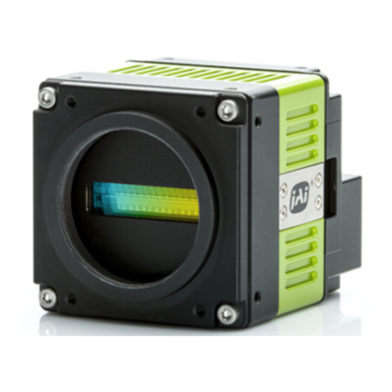
SW-4000TL-PMCL
High Speed CMOS Trilinear Camera
���������������������3
��������������������������������3���������
Thank you for purchasing this product.
Be sure to read this manual before use.
This manual includes important safety precautions and instructions on how
to operate the unit. Be sure to read this manual to ensure proper operation.
The contents of this manual are subject to change without notice for the
purpose of improvement.
© 2018 JAI
Advertisement

Summary of Contents for IAI SW-4000TL-PMCL
- Page 1 Command List SW-4000TL-PMCL High Speed CMOS Trilinear Camera ���������������������3 ��������������������������������3��������� Thank you for purchasing this product. Be sure to read this manual before use. This manual includes important safety precautions and instructions on how to operate the unit. Be sure to read this manual to ensure proper operation.
- Page 2 Communication Protocol for SW-4000TL-PMCL <Rev 0.3> All configuration of the camera is done via the RS-232C port. The camera can be set up from a PC running terminal emulator software. Below is the description of the ASCII based short command protocol.
- Page 3 3 3 3 3 ..3 3 3 3 ..Switching baud rate between PC and camera Camera always starts up with 9600bps. This can be switched to higher baud rates after a communication has been established.
- Page 4 Name Access Short ASCII Values DEFAULT Description DVN?<CR><LF> DeviceVendorName "JAI Corporation" Display the manufacture name. MD?<CR><LF> DeviceModelName "SW-4000TL-PMCL" Display the model name. DV?<CR><LF> Indicate device version DeviceVersion (e.g. “0.1.0.0” ) Display the camera version. VN?<CR><LF> DeviceFirmwareVersion "*.*.*.*" Display the version of firmware.
- Page 5 VB=[Param.]<CR><LF> VB?<CR><LF> 1: Binning Off BinningVertical 2: Binning On Set the number of pixels in the vertical direction for which to perform binning. BA=[Param.]<CR><LF> 0:RGB8 BA?<CR><LF> PixelFormat 1:RGB10 Set the pixel format. 0:Off TPN=[Param.]<CR><LF> 1:White TPN?<CR><LF> TestImageSelector 2:Gray Pattern 1 (Ramp) 3:Gray Pattern 2 (Stripe) Select the test image.
- Page 6 PEMAX?<CR><LF> ExposureTimeMax PEMAX Display the maximum value that can be set to [ExposureTime]. LROP=[Param.]<CR><LF> LROP?<CR><LF> 0: mode1 AcquisitionLineRateOption LROP 1: mode2 Set the [AcquisitionLineRateOption]. If mode2 is selected, the maximum line rate is limited. AnalogControl Name Access Short ASCII Values DEFAULT Description GM=[Param.]<CR><LF>...
- Page 7 BL=[Param.]<CR><LF> BL?<CR><LF> BlackLevel[DigitalAll] -133 -133~255 Controls the analog black level as an absolute physical value. This represents a DC offset applied to the video signal. BLR=[Param.]<CR><LF> BLR?<CR><LF> BlackLevel[DigitalRed] -64~64 Controls the analog black level as an absolute physical value. This represents a DC offset applied to the video signal.
- Page 8 CMVRR=[Param.]<CR><LF> CMVRR?<CR><LF> ColorMatrixValue[R-R] CMVRR -20000 20000 -20000~20000 ColorTransformationMode = RGB, ColorTransformationRGBMode=UserCustom Individual adjust 9 elements of the 3x3 color matrix (R-R). CMVRG=[Param.]<CR><LF> CMVRG?<CR><LF> ColorMatrixValue[R-G] CMVRG -20000~20000 -20000 20000 ColorTransformationMode = RGB, ColorTransformationRGBMode=UserCustom Individual adjust 9 elements of the 3x3 color matrix (R-G). CMVRB=[Param.]<CR><LF>...
- Page 9 LI3=[Param.]<CR><LF> LI3?<CR><LF> LineInverter[TTLOut4] False/True Invert the polarity of the signal(TTLOut4). ND0INV1=[Param.]<CR><LF> ND0INV1?<CR><LF> LineInverter[NANDGate0In1 ] ND0INV1 False/True Invert the polarity of the signal(NANDGate0In1). ND0INV2=[Param.]<CR><LF> ND0INV2?<CR><LF> LineInverter[NANDGate0In2 ] ND0INV2 False/True Invert the polarity of the signal(NANDGate0In2). ND1INV1=[Param.]<CR><LF> ND1INV1?<CR><LF> ND1INV1 LineInverter[NANDGate1In1] False/True Invert the polarity of the signal(NANDGate1In1). ND1INV2=[Param.]<CR><LF>...
- Page 10 ND1IN2=[Param.]<CR><LF> ND1IN2?<CR><LF> ND1IN2 LineSource[NANDGate1In2] Same as LI0 Select signal to be passed to the Line selected by Line Selector 0: Off OPTFL=[Param.]<CR><LF> 1: 0.1 us OPTFL?<CR><LF> 2: 1 us OPTFL OptInFilterSelector 3: 5 us 4: 10 us Set the noise elimination level of OptIO input signal of 5: 50 us DigitalIO 6:...
- Page 11 CV0?<CR><LF> CounterValue[Counter0] 0~4294967295 Display the counter value. CV1?<CR><LF> CounterValue[Counter1] 0~4294967295 Display the counter value. CV2?<CR><LF> CounterValue[Counter2] 0~4294967295 Display the counter value. CV3?<CR><LF> CounterValue[Counter3] 0~4294967295 Display the counter value. UserSetControl Name Access Short ASCII Values DEFAULT Description LD=[Param.]<CR><LF> 0:Default LD?<CR><LF> 1:UserSet1 UserSetLoad 2:UserSet2 Loads the User Set specified by UserSetSelector to the...
- Page 12 PGL2=[Param.]<CR><LF> PGL2?<CR><LF> PulseGeneratorLength[PulseGener 1048575 1000000 PGL2 1~1048575 ator2] PulseGeneratorLength in PulseGeneratorClock ticks. This is the total length of the pulse for every time it is repeated. PGL3=[Param.]<CR><LF> PGL3?<CR><LF> PulseGeneratorLength[PulseGener PGL3 1~1048575 1048575 1000000 ator3] PulseGeneratorLength in PulseGeneratorClock ticks. This is the total length of the pulse for every time it is repeated.
- Page 13 PGRPT3=[Param.]<CR><LF> PulseGeneratorRepeatCount[Pulse PGRPT3?<CR><LF> PGRPT3 0~255 Generator3] PulseGeneratorRepeatCount. 0 is Infinite 0: Off PGCM0=[Param.]<CR><LF> 1: LevelHigh PulseGeneratorClearActivation[Pul PGCM0?<CR><LF> PGCM0 2: LevelLow seGenerator0] Selects the activation mode of the input to clear the Pulse 3: RisingEdge Generator. 4: FallingEdge PGCM1=[Param.]<CR><LF> PGCM1?<CR><LF> PulseGeneratorClearActivation[Pul PGCM1 Same as PGCM0 seGenerator1] Selects the activation mode of the input to clear the Pulse Generator.
- Page 14 PGINV3=[Param.]<CR><LF> PGINV3?<CR><LF> PulseGeneratorClearInverter[Puls PGINV3 False/True eGenerator3] Controls if the pulse generator clear signal is inverted. False means "Active High" and True for "Active Low". PGSM0=[Param.]<CR><LF> PulseGeneratorClearSyncMode[Pu 0: Async Mode PGSM0?<CR><LF> PGSM0 lseGenerator0] 1: Sync Mode Selects the sync mode of the input to clear the Pulse Generator.
- Page 15 JAICustomControlPixelCorrection Access Short ASCII Name Values DEFAULT Description PBC=[Param.]<CR><LF> 0: Off PBC?<CR><LF> 1: Default PixelBlackCorrectionMode 2: User1 3: User2 Select the user area to which to save the black level 4: User3 correction value. PBR<CR><LF> Generate black level correction data automatically from the captured image. PerformPixelBlackCalibration Caution When [PixelBlackCorrectionMode] is set to [Off] or [Default]...
- Page 16 SPCG=[Param.]<CR><LF> SPCG?<CR><LF> SpartialCompensationG SPCG 0~80 Set the compensation value for G-Channel. SPCB=[Param.]<CR><LF> SPCB?<CR><LF> SpartialCompensationB SPCB 0~80 Set the compensation value for B-Channel. SPCD=[Param.]<CR><LF> SPCD?<CR><LF> SpartialCompensationDistance SPCD 5~20 Set "How much to move during one trigger the image is on the sensor pixel". JAICustomControlVideoProcess Name Access Short ASCII...
- Page 17 ENFIL=[Param.]<CR><LF> ENFIL?<CR><LF> EncoderFilter ENFIL 1~15 Apply a low-pass filter to prevent noise on the signal from the rotary encoder and stabilize the signal for the specified number of cycles. ENSTR=[Param.]<CR><LF> ENSTR?<CR><LF> EncoderStrobe ENSTR 1~256 Set the strobe length of the Trigger signal generated from the rotary encoder by the number of cycles...


Need help?
Do you have a question about the SW-4000TL-PMCL and is the answer not in the manual?
Questions and answers